 Products Home
Fixed Magnification Beam Expanders: Achromatic

- 2X, 3X, 5X, 10X, 15X, or 20X Beam Expansion
- Sliding Lens Design for Collimation Adjustment
- 3 Broadband AR Coatings Available
GBE02-B
2X Beam Expander
650 - 1050 nm AR Coating
GBE05-C
5X Beam Expander
1050 - 1650 nm AR Coating
GBE20-A
20X Beam Expander
400 - 650 nm AR Coating
GBE10-B
10X Beam Expander
650 - 1050 nm AR Coating


Please Wait

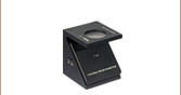
Click to Enlarge
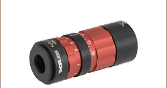
A GBE15-C 15X Beam Expander Post Mounted with two SM2RC Slip Rings

Click for Details
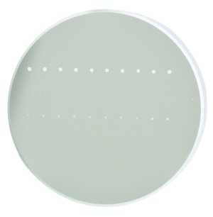
Input (Back) and Output (Front) Apertures of the GBE02-B 2X Beam Expander
Features
- 2X, 3X, 5X,10X, 15X, or 20X Beam Expansion or Reduction
- 3 Broadband AR Coating Wavelength Ranges
- A: 400 - 650 nm
- B: 650 - 1050 nm
- C: 1050 - 1650 nm
- Sliding Lens Adjustment that Minimizes Beam Walk Off
- Housing with Fixed Mechanical Length and Non-Rotating Ends
- Collimation Adjustment Ring can be Locked with Included Hex Key
- Can be Used to Reduce Beam Size by Using the Larger Aperture as the Input
- Threaded Apertures for Integration into Optical Systems
Thorlabs' Achromatic AR-Coated Galilean Beam Expanders can expand or reduce the diameter of a collimated beam by a factor of 2, 3, 5, 10, 15 or 20. These beam expanders use a low-aberration, achromatic design optimized to provide a wavefront error of less than λ/4 (i.e., diffraction-limited performance) and minimize the impact on the M² value of the expanded beam. An expanded beam can be focused to a narrow diffraction-limited waist, which can be necessary for use with optics or instruments that have small input apertures such as our Fabry-Perot interferometers.
The beam expanders use an achromat and a lens fabricated from N-BK7 and N-BASF2. To minimize reflections at the air-to-glass interfaces, the optics used in these beam expanders have one of three broadband AR coatings deposited on both sides of each lens incorporated into the design: 400 - 650 nm (Item # ending in -A), 650 - 1050 nm (Item # ending in -B), or 1050 - 1650 nm (Item # ending in -C). The AR coatings reduce the maximum reflectance per surface to <0.5% over the specified coating ranges, compared to a typical reflectance of 4% per surface for an uncoated optic. See the Specs and AR Coatings tabs for more information on the coating performance.
The sliding lens design allows for the collimation to be adjusted while minimizing the beam walk-off effect that is inherent to lens adjustments. The red ring, shown in the photos above, is used to adjust the output beam collimation; once the desired collimation is obtained, the ring can be locked by tightening the locking screw using the included 0.05" hex key. The housing is designed so that it does not rotate when turning the collimation adjustment ring, allowing the user to adjust the divergence without disturbing any attached optics and maintain pointing stability.
Mounting Features
These Galilean beam expanders have threaded input and output apertures, which allow additional lenses and filters to be installed easily along the optical axis of the beam expander. The input of each beam expander has internal SM05 (0.535"-40) and external SM1 (1.035"-40) threads for ease of use with Thorlabs' lens tubes and other optical components. The output of the 2X beam expanders is externally SM1 threaded as well. The beam expanders with 3X, 5X, or 10X expansion have an externally M43 x 0.5-threaded output, which can be integrated with SM2 (2.035"-40) threaded components by using the SM2A30 adapter. The Ø1.2" section of the barrel on the 2X, 3X, 5X, and 10X beam expanders provides a smooth mounting surface with the same diameter as our Ø1" lens tubes. The 15X and 20X beam expanders have an externally SM2-threaded output and should be mounted using the wider Ø2.2" section of the housing, which is the same diameter as our Ø2" lens tubes. See the Drawings tab for details.
Post mounting options include the SM1RC(/M) Lens Tube Slip Ring and SM1TC Lens Tube Clamp. Alternatively, the 2X through 10X beam expanders can be integrated in one of our cage systems via the CP36 30 mm Cage Plate or by using the SM2A21 mounting adapter with the LCP35 60 mm cage plate. 15X and 20X beam expanders can be mounted directly into a 60 mm cage system using the LCP36 cage plate. We also offer the SM1A52 adapter, which allows the input to be mated with components using the M30 x 1.0 thread standard. Recommended mounts are available below.
Thorlabs offers other fixed magnification beam expanders with UV fused silica optical elements for narrowband applications, ZnSe optical elements for use in mid-IR applications, or reflective designs that use mirrors for cases where chromatic aberration is a concern. Variable magnification beam expanders, including our UV fused silica or achromatic zoom beam expanders, are also available. For more information on our extensive line of beam expanders, please see the Beam Expanders tab.
| Item # Prefix | GBE02 | GBE03 | GBE05 | GBE10 | GBE15 | GBE20 |
|---|---|---|---|---|---|---|
| Expansion | 2X | 3X | 5X | 10X | 15X | 20X |
| Max Input Beam Diameter | 9.7 mm | 10.6 mm | 7.0 mm | 3.5 mm | 2.9 mm | 2.2 mm |
| Diffraction-Limited Input Beam Diametera | 8.5 mm | 9.0 mm | 5.0 mm | 3.0 mm | 2.5 mm | 2.0 mm |
| Closest Focusing Distance | ±1.2 m | ±3.0 m | ±2.5 m | ±5.5 m | ±20 m | ±55 m |
| Input Thread | Internal: SM05 (0.535"-40) External: SM1 (1.035"-40) |
|||||
| Output Thread (External) | SM1 (1.035"-40) | M43 x 0.5b | SM2 (2.035"-40) | |||
| Surface Quality | 20-10 Scratch-Dig | |||||
| Housing Dimensions | ||||||
| Input Housing Diameter | 30.5 mm (1.20") | |||||
| Output Housing Diameter | 30.5 mm (1.20") | 45.0 mm (1.77") | 55.9 mm (2.20") | |||
| Housing Length | 52.0 mm (2.05") | 85.5 mm (3.37") | 135.0 mm (5.31") | 202.0 mm (7.95") | 267.0 mm (10.51") | |
| AR Coating Specifications | |||
|---|---|---|---|
| Item # Suffix | -A | -B | -C |
| Typical Transmission | ≥93% @ 405 nm ≥96% @ 543 nm ≥98% @ 633 nm |
≥96% @ 780 nm ≥96% @ 980 nm |
≥96% @ 1064 nm ≥97% @ 1310 nm ≥97% @ 1550 nm |
| Coating Type | Broadband Antireflection | ||
| Coating Range | 400 - 650 nm | 650 - 1050 nm | 1050 - 1650 nm |
| Max Reflectance per Surface | <0.5% | ||
| Damage Thresholda | 3 J/cm² (532 nm, 10 Hz, 10 ns, Ø408 μm) | 7.5 J/cm² (810 nm, 10 Hz, 10 ns, Ø76.9 μm) | 3 J/cm² (1542 nm, 1 Hz, 10 ns, Ø268 μm) |
The graphs below show the reflectance per surface with respect to wavelength of the AR coatings deposited on both sides of each lens incorporated in our achromatic Galilean beam expanders. The blue shaded region indicates the wavelength range specified for each coating. The table below provides the specifications for each coating.

Click to Enlarge
The blue shaded region indicates the specified operating wavlength range for the coating. Performance outside of this region is not guaranteed.
Click to Enlarge
Click Here for Raw Data
The blue shaded region indicates the specified operating wavlength range for the coating. Performance outside of this region is not guaranteed.

Click to Enlarge
Click Here for Raw Data
The blue shaded region indicates the specified operating wavlength range for the coating. Performance outside of this region is not guaranteed.
| Antireflection Coatings | |||||
|---|---|---|---|---|---|
| Item # Suffix | Wavelength Range | Reflectance per Surface | |||
| -A | 400 - 650 nma | RMax < 0.5% | |||
| -B | 650 - 1050 nm | RMax < 0.5% | |||
| -C | 1050 - 1650 nm | RMax < 0.5% | |||
Simplified mechanical drawings are provided below to provide a comparison of the profiles of the beam expanders. For complete mechanical drawings, go to the Documents tab and click on the red icon (![]() ) next to one of the item numbers to view the support documentation for that part. Recommended mounting options are provided at the bottom of the page.
) next to one of the item numbers to view the support documentation for that part. Recommended mounting options are provided at the bottom of the page.

Click for Details
The GBE02-A beam expander viewed from the side. Each 2X beam expander shares the same profile.

Click for Details
The GBE03-A beam expander viewed from the side. Each 3X and 5X beam expander shares the same profile.

Click for Details
The GBE10-A beam expander viewed from the side. Each 10X beam expander shares the same profile.

Click for Details
The GBE15-A beam expander viewed from the side. Each 15X beam expander shares the same profile.

Click for Details
The GBE20-A beam expander viewed from the side. Each 20X beam expander shares the same profile.
| Damage Threshold Specifications | |
|---|---|
| Item # Suffix | Damage Threshold |
| -A | 3 J/cm² (532 nm, 10 Hz, 10 ns, Ø408 μm) |
| -B | 7.5 J/cm² (810 nm, 10 Hz, 10 ns, Ø76.9 μm) |
| -C | 3 J/cm² (1542 nm, 1 Hz, 10 ns, Ø268 μm) |
Damage Threshold Data for Thorlabs' Achromatic Galilean Beam Expanders
The specifications to the right are measured data for Thorlabs' Achromatic Galilean Beam Expanders. This is the damage threshold of the AR Coating, which limits the power that the beam expander can accept. Note that if these items are being used to reduce the size of a beam, the power at the exit aperture must not exceed this damage threshold.
Laser Induced Damage Threshold Tutorial
The following is a general overview of how laser induced damage thresholds are measured and how the values may be utilized in determining the appropriateness of an optic for a given application. When choosing optics, it is important to understand the Laser Induced Damage Threshold (LIDT) of the optics being used. The LIDT for an optic greatly depends on the type of laser you are using. Continuous wave (CW) lasers typically cause damage from thermal effects (absorption either in the coating or in the substrate). Pulsed lasers, on the other hand, often strip electrons from the lattice structure of an optic before causing thermal damage. Note that the guideline presented here assumes room temperature operation and optics in new condition (i.e., within scratch-dig spec, surface free of contamination, etc.). Because dust or other particles on the surface of an optic can cause damage at lower thresholds, we recommend keeping surfaces clean and free of debris. For more information on cleaning optics, please see our Optics Cleaning tutorial.
Testing Method
Thorlabs' LIDT testing is done in compliance with ISO/DIS 11254 and ISO 21254 specifications.
First, a low-power/energy beam is directed to the optic under test. The optic is exposed in 10 locations to this laser beam for 30 seconds (CW) or for a number of pulses (pulse repetition frequency specified). After exposure, the optic is examined by a microscope (~100X magnification) for any visible damage. The number of locations that are damaged at a particular power/energy level is recorded. Next, the power/energy is either increased or decreased and the optic is exposed at 10 new locations. This process is repeated until damage is observed. The damage threshold is then assigned to be the highest power/energy that the optic can withstand without causing damage. A histogram such as that below represents the testing of one BB1-E02 mirror.
The photograph above is a protected aluminum-coated mirror after LIDT testing. In this particular test, it handled 0.43 J/cm2 (1064 nm, 10 ns pulse, 10 Hz, Ø1.000 mm) before damage.
| Example Test Data | |||
|---|---|---|---|
| Fluence | # of Tested Locations | Locations with Damage | Locations Without Damage |
| 1.50 J/cm2 | 10 | 0 | 10 |
| 1.75 J/cm2 | 10 | 0 | 10 |
| 2.00 J/cm2 | 10 | 0 | 10 |
| 2.25 J/cm2 | 10 | 1 | 9 |
| 3.00 J/cm2 | 10 | 1 | 9 |
| 5.00 J/cm2 | 10 | 9 | 1 |
According to the test, the damage threshold of the mirror was 2.00 J/cm2 (532 nm, 10 ns pulse, 10 Hz, Ø0.803 mm). Please keep in mind that these tests are performed on clean optics, as dirt and contamination can significantly lower the damage threshold of a component. While the test results are only representative of one coating run, Thorlabs specifies damage threshold values that account for coating variances.
Continuous Wave and Long-Pulse Lasers
When an optic is damaged by a continuous wave (CW) laser, it is usually due to the melting of the surface as a result of absorbing the laser's energy or damage to the optical coating (antireflection) [1]. Pulsed lasers with pulse lengths longer than 1 µs can be treated as CW lasers for LIDT discussions.
When pulse lengths are between 1 ns and 1 µs, laser-induced damage can occur either because of absorption or a dielectric breakdown (therefore, a user must check both CW and pulsed LIDT). Absorption is either due to an intrinsic property of the optic or due to surface irregularities; thus LIDT values are only valid for optics meeting or exceeding the surface quality specifications given by a manufacturer. While many optics can handle high power CW lasers, cemented (e.g., achromatic doublets) or highly absorptive (e.g., ND filters) optics tend to have lower CW damage thresholds. These lower thresholds are due to absorption or scattering in the cement or metal coating.
LIDT in linear power density vs. pulse length and spot size. For long pulses to CW, linear power density becomes a constant with spot size. This graph was obtained from [1].
Pulsed lasers with high pulse repetition frequencies (PRF) may behave similarly to CW beams. Unfortunately, this is highly dependent on factors such as absorption and thermal diffusivity, so there is no reliable method for determining when a high PRF laser will damage an optic due to thermal effects. For beams with a high PRF both the average and peak powers must be compared to the equivalent CW power. Additionally, for highly transparent materials, there is little to no drop in the LIDT with increasing PRF.
In order to use the specified CW damage threshold of an optic, it is necessary to know the following:
- Wavelength of your laser
- Beam diameter of your beam (1/e2)
- Approximate intensity profile of your beam (e.g., Gaussian)
- Linear power density of your beam (total power divided by 1/e2 beam diameter)
Thorlabs expresses LIDT for CW lasers as a linear power density measured in W/cm. In this regime, the LIDT given as a linear power density can be applied to any beam diameter; one does not need to compute an adjusted LIDT to adjust for changes in spot size, as demonstrated by the graph to the right. Average linear power density can be calculated using the equation below.
The calculation above assumes a uniform beam intensity profile. You must now consider hotspots in the beam or other non-uniform intensity profiles and roughly calculate a maximum power density. For reference, a Gaussian beam typically has a maximum power density that is twice that of the uniform beam (see lower right).
Now compare the maximum power density to that which is specified as the LIDT for the optic. If the optic was tested at a wavelength other than your operating wavelength, the damage threshold must be scaled appropriately. A good rule of thumb is that the damage threshold has a linear relationship with wavelength such that as you move to shorter wavelengths, the damage threshold decreases (i.e., a LIDT of 10 W/cm at 1310 nm scales to 5 W/cm at 655 nm):
While this rule of thumb provides a general trend, it is not a quantitative analysis of LIDT vs wavelength. In CW applications, for instance, damage scales more strongly with absorption in the coating and substrate, which does not necessarily scale well with wavelength. While the above procedure provides a good rule of thumb for LIDT values, please contact Tech Support if your wavelength is different from the specified LIDT wavelength. If your power density is less than the adjusted LIDT of the optic, then the optic should work for your application.
Please note that we have a buffer built in between the specified damage thresholds online and the tests which we have done, which accommodates variation between batches. Upon request, we can provide individual test information and a testing certificate. The damage analysis will be carried out on a similar optic (customer's optic will not be damaged). Testing may result in additional costs or lead times. Contact Tech Support for more information.
Pulsed Lasers
As previously stated, pulsed lasers typically induce a different type of damage to the optic than CW lasers. Pulsed lasers often do not heat the optic enough to damage it; instead, pulsed lasers produce strong electric fields capable of inducing dielectric breakdown in the material. Unfortunately, it can be very difficult to compare the LIDT specification of an optic to your laser. There are multiple regimes in which a pulsed laser can damage an optic and this is based on the laser's pulse length. The highlighted columns in the table below outline the relevant pulse lengths for our specified LIDT values.
Pulses shorter than 10-9 s cannot be compared to our specified LIDT values with much reliability. In this ultra-short-pulse regime various mechanics, such as multiphoton-avalanche ionization, take over as the predominate damage mechanism [2]. In contrast, pulses between 10-7 s and 10-4 s may cause damage to an optic either because of dielectric breakdown or thermal effects. This means that both CW and pulsed damage thresholds must be compared to the laser beam to determine whether the optic is suitable for your application.
| Pulse Duration | t < 10-9 s | 10-9 < t < 10-7 s | 10-7 < t < 10-4 s | t > 10-4 s |
|---|---|---|---|---|
| Damage Mechanism | Avalanche Ionization | Dielectric Breakdown | Dielectric Breakdown or Thermal | Thermal |
| Relevant Damage Specification | No Comparison (See Above) | Pulsed | Pulsed and CW | CW |
When comparing an LIDT specified for a pulsed laser to your laser, it is essential to know the following:
LIDT in energy density vs. pulse length and spot size. For short pulses, energy density becomes a constant with spot size. This graph was obtained from [1].
- Wavelength of your laser
- Energy density of your beam (total energy divided by 1/e2 area)
- Pulse length of your laser
- Pulse repetition frequency (prf) of your laser
- Beam diameter of your laser (1/e2 )
- Approximate intensity profile of your beam (e.g., Gaussian)
The energy density of your beam should be calculated in terms of J/cm2. The graph to the right shows why expressing the LIDT as an energy density provides the best metric for short pulse sources. In this regime, the LIDT given as an energy density can be applied to any beam diameter; one does not need to compute an adjusted LIDT to adjust for changes in spot size. This calculation assumes a uniform beam intensity profile. You must now adjust this energy density to account for hotspots or other nonuniform intensity profiles and roughly calculate a maximum energy density. For reference a Gaussian beam typically has a maximum energy density that is twice that of the 1/e2 beam.
Now compare the maximum energy density to that which is specified as the LIDT for the optic. If the optic was tested at a wavelength other than your operating wavelength, the damage threshold must be scaled appropriately [3]. A good rule of thumb is that the damage threshold has an inverse square root relationship with wavelength such that as you move to shorter wavelengths, the damage threshold decreases (i.e., a LIDT of 1 J/cm2 at 1064 nm scales to 0.7 J/cm2 at 532 nm):
You now have a wavelength-adjusted energy density, which you will use in the following step.
Beam diameter is also important to know when comparing damage thresholds. While the LIDT, when expressed in units of J/cm², scales independently of spot size; large beam sizes are more likely to illuminate a larger number of defects which can lead to greater variances in the LIDT [4]. For data presented here, a <1 mm beam size was used to measure the LIDT. For beams sizes greater than 5 mm, the LIDT (J/cm2) will not scale independently of beam diameter due to the larger size beam exposing more defects.
The pulse length must now be compensated for. The longer the pulse duration, the more energy the optic can handle. For pulse widths between 1 - 100 ns, an approximation is as follows:
Use this formula to calculate the Adjusted LIDT for an optic based on your pulse length. If your maximum energy density is less than this adjusted LIDT maximum energy density, then the optic should be suitable for your application. Keep in mind that this calculation is only used for pulses between 10-9 s and 10-7 s. For pulses between 10-7 s and 10-4 s, the CW LIDT must also be checked before deeming the optic appropriate for your application.
Please note that we have a buffer built in between the specified damage thresholds online and the tests which we have done, which accommodates variation between batches. Upon request, we can provide individual test information and a testing certificate. Contact Tech Support for more information.
[1] R. M. Wood, Optics and Laser Tech. 29, 517 (1998).
[2] Roger M. Wood, Laser-Induced Damage of Optical Materials (Institute of Physics Publishing, Philadelphia, PA, 2003).
[3] C. W. Carr et al., Phys. Rev. Lett. 91, 127402 (2003).
[4] N. Bloembergen, Appl. Opt. 12, 661 (1973).

In order to illustrate the process of determining whether a given laser system will damage an optic, a number of example calculations of laser induced damage threshold are given below. For assistance with performing similar calculations, we provide a spreadsheet calculator that can be downloaded by clicking the LIDT Calculator button. To use the calculator, enter the specified LIDT value of the optic under consideration and the relevant parameters of your laser system in the green boxes. The spreadsheet will then calculate a linear power density for CW and pulsed systems, as well as an energy density value for pulsed systems. These values are used to calculate adjusted, scaled LIDT values for the optics based on accepted scaling laws. This calculator assumes a Gaussian beam profile, so a correction factor must be introduced for other beam shapes (uniform, etc.). The LIDT scaling laws are determined from empirical relationships; their accuracy is not guaranteed. Remember that absorption by optics or coatings can significantly reduce LIDT in some spectral regions. These LIDT values are not valid for ultrashort pulses less than one nanosecond in duration.
Figure 71A A Gaussian beam profile has about twice the maximum intensity of a uniform beam profile.
CW Laser Example
Suppose that a CW laser system at 1319 nm produces a 0.5 W Gaussian beam that has a 1/e2 diameter of 10 mm. A naive calculation of the average linear power density of this beam would yield a value of 0.5 W/cm, given by the total power divided by the beam diameter:
However, the maximum power density of a Gaussian beam is about twice the maximum power density of a uniform beam, as shown in Figure 71A. Therefore, a more accurate determination of the maximum linear power density of the system is 1 W/cm.
An AC127-030-C achromatic doublet lens has a specified CW LIDT of 350 W/cm, as tested at 1550 nm. CW damage threshold values typically scale directly with the wavelength of the laser source, so this yields an adjusted LIDT value:
The adjusted LIDT value of 350 W/cm x (1319 nm / 1550 nm) = 298 W/cm is significantly higher than the calculated maximum linear power density of the laser system, so it would be safe to use this doublet lens for this application.
Pulsed Nanosecond Laser Example: Scaling for Different Pulse Durations
Suppose that a pulsed Nd:YAG laser system is frequency tripled to produce a 10 Hz output, consisting of 2 ns output pulses at 355 nm, each with 1 J of energy, in a Gaussian beam with a 1.9 cm beam diameter (1/e2). The average energy density of each pulse is found by dividing the pulse energy by the beam area:
As described above, the maximum energy density of a Gaussian beam is about twice the average energy density. So, the maximum energy density of this beam is ~0.7 J/cm2.
The energy density of the beam can be compared to the LIDT values of 1 J/cm2 and 3.5 J/cm2 for a BB1-E01 broadband dielectric mirror and an NB1-K08 Nd:YAG laser line mirror, respectively. Both of these LIDT values, while measured at 355 nm, were determined with a 10 ns pulsed laser at 10 Hz. Therefore, an adjustment must be applied for the shorter pulse duration of the system under consideration. As described on the previous tab, LIDT values in the nanosecond pulse regime scale with the square root of the laser pulse duration:
This adjustment factor results in LIDT values of 0.45 J/cm2 for the BB1-E01 broadband mirror and 1.6 J/cm2 for the Nd:YAG laser line mirror, which are to be compared with the 0.7 J/cm2 maximum energy density of the beam. While the broadband mirror would likely be damaged by the laser, the more specialized laser line mirror is appropriate for use with this system.
Pulsed Nanosecond Laser Example: Scaling for Different Wavelengths
Suppose that a pulsed laser system emits 10 ns pulses at 2.5 Hz, each with 100 mJ of energy at 1064 nm in a 16 mm diameter beam (1/e2) that must be attenuated with a neutral density filter. For a Gaussian output, these specifications result in a maximum energy density of 0.1 J/cm2. The damage threshold of an NDUV10A Ø25 mm, OD 1.0, reflective neutral density filter is 0.05 J/cm2 for 10 ns pulses at 355 nm, while the damage threshold of the similar NE10A absorptive filter is 10 J/cm2 for 10 ns pulses at 532 nm. As described on the previous tab, the LIDT value of an optic scales with the square root of the wavelength in the nanosecond pulse regime:
This scaling gives adjusted LIDT values of 0.08 J/cm2 for the reflective filter and 14 J/cm2 for the absorptive filter. In this case, the absorptive filter is the best choice in order to avoid optical damage.
Pulsed Microsecond Laser Example
Consider a laser system that produces 1 µs pulses, each containing 150 µJ of energy at a repetition rate of 50 kHz, resulting in a relatively high duty cycle of 5%. This system falls somewhere between the regimes of CW and pulsed laser induced damage, and could potentially damage an optic by mechanisms associated with either regime. As a result, both CW and pulsed LIDT values must be compared to the properties of the laser system to ensure safe operation.
If this relatively long-pulse laser emits a Gaussian 12.7 mm diameter beam (1/e2) at 980 nm, then the resulting output has a linear power density of 5.9 W/cm and an energy density of 1.2 x 10⁻⁴ J/cm2 per pulse. This can be compared to the LIDT values for a WPQ10E-980 polymer zero-order quarter-wave plate, which are 5 W/cm for CW radiation at 810 nm and 5 J/cm2 for a 10 ns pulse at 810 nm. As before, the CW LIDT of the optic scales linearly with the laser wavelength, resulting in an adjusted CW value of 6 W/cm at 980 nm. On the other hand, the pulsed LIDT scales with the square root of the laser wavelength and the square root of the pulse duration, resulting in an adjusted value of 55 J/cm2 for a 1 µs pulse at 980 nm. The pulsed LIDT of the optic is significantly greater than the energy density of the laser pulse, so individual pulses will not damage the wave plate. However, the large average linear power density of the laser system may cause thermal damage to the optic, much like a high-power CW beam.
| Posted Comments: | |
Gert-Jan Bakker
(posted 2025-01-14 14:20:37.297) Dear Thorlabs employee,
I have a question about the fixed and zoom achromatic beam expanders. Are these beam expanders designed for a specific wavelength range, considering spherical and chromatic aberrations? At which wavelengths do they perform best and are there differences between the designs for the different wavelength ranges, or is it only the AR coating which is different? How stable is the divergence when set to a particular value, upon change of the wavelength?
Thank you very much for your response!
With best regards,
Gert-Jan mkarlsson
(posted 2025-01-21 12:51:19.0) Dear Gert-Jan,
Thank you for your inquiry! We have reached out to you directly to discuss your application in more detail. Yixuan Zhao
(posted 2024-11-26 10:44:33.18) Hi,
May I ask about the description "The sliding lens design allows for the collimation to be adjusted while minimizing the beam walk-off effect that is inherent to lens adjustments",
1. How the sliding lens works to collimate beam? Could you please provide steps of using sliding lens to collimate?
2. what is the definition of walk-off effect and its performances in optical experiments?
3. why the diameter of beam size changes when changing the sliding lens, while the magnification is fixed?
Thanks for your help! Looking forward to your reply. Benedikt Krämer
(posted 2024-05-24 14:28:21.27) Hallo Tholabs Team,
wir würden gerne das GBE05-B in ein Kundensystem (Mikroskop) einbauen und bräuchten eine ROHS Bescheinigung oder eine ROHS Exemption.
Wäre das möglich diese zu schicken?
Vielen Dank und mit freundlichen Grüßen,
Benedikt Krämer acanales
(posted 2024-05-28 07:21:27.0) Thank you for contacting us! We have reached out to you directly with the RoHS document. The website will be updated to include the document. Son Chang Gyun
(posted 2024-05-07 15:11:09.607) Hello, could you please provide with some information about the focal length, material and thickness(Lens, Lens to Lens)? (GBE03-A, GBE05-A and GBE15-A)
I need information about the lens for the design of the illumination optics. Thank you mkarlsson
(posted 2024-05-08 05:39:07.0) Hello, thank you for your inquiry! We are able to share some information that is not directly available through the website. I have reached out to you directly to discuss your application further. Martin Rabault
(posted 2024-01-09 11:49:49.94) Hello, could you please provide with some information about the focal length of both lenses of the GBE10-C and GBE05-C? Thank you very much mkarlsson
(posted 2024-01-09 09:27:23.0) Thank you for your inquiry! I've reached out to you directly to discuss this further. ziyu zhan
(posted 2023-12-12 13:58:27.593) Would you mind telling only the focal length of two lens in this product to me? It is really important to me. Thank you all the same. mkarlsson
(posted 2023-12-14 05:12:03.0) Thank you for reaching out Ziyu. I have contacted you directly to discuss your inquiry. Kevin M
(posted 2023-02-20 17:26:25.74) Hello,
I am trying to use a 2x beam expander and a 20mm focal length diffraction limited aspheric lens to reduce a laser beam down to a smaller focal spot size, however using the beam expander makes no difference / makes the beam larger.
The beam expander is placed in the path of a 1064nm 8mm diameter collimated beam which when expanded passes through the ashpere onto a CMOS for spot size measurement. Are the lenses in the expander suitable for such a spot size reduction? We are using a GBE02-C - 2X Achromatic Galilean Beam Expander with AR coating.
Thanks,
Kevin fnero
(posted 2023-02-22 03:50:02.0) Thank you for your feedback. In general terms, a larger beam can be focused down to a smaller spot size. Our beam expanders can be used for this purpose, but other parameters also affect the spot size in an application as yours. For example, it is important that the aspheric lens has diffraction limited performance at the wavelength you are using. We have reached out to you to further discuss your application. 諒一 芝山
(posted 2022-10-27 15:01:39.237) 同製品を使用した系全体に対し、物理光学伝搬による光学解析を行いたいです。そのため、ブラックボックスデータを含まないZemaxモデルを頂くことは可能でしょうか? Evgenii Zherebtsov
(posted 2022-08-26 14:35:36.72) Hello!
What are the limits of the beam divergence adjustment on the beam expander GBE10-B - 10X?
Many thanks! fnero
(posted 2022-09-19 02:23:07.0) Thank you for reaching out to us. The inner lens cell can be moved +/-5mm for all fixed beam expanders. For the GBE10-B it will result in a focus range of appr. +/-4.5m for a collimated input beam. user
(posted 2022-06-07 14:49:39.22) What is focusing distance range of model GBE10-A for 633nm wavelength? cdolbashian
(posted 2022-06-17 04:48:31.0) Thank you for reaching out to us Pawel, I have contacted you directly to discuss your inquiry. user
(posted 2022-05-26 16:40:07.883) I would like to use the GBE05-C as a beam reducer. Could you please provide a Zemax model for the reverse direction? ksosnowski
(posted 2022-06-06 04:55:27.0) Thanks for reaching out to us. Upon request we can provide reverse blackbox files for most of the beam expanders. I have reached out directly to discuss your application further. Gauthier Malbrancke
(posted 2022-05-13 15:45:40.887) Hi, I need a 3X beam expander to work from 400 nm to 1000 nm.
What would be the most appropriate coating to maximize the transmission and minimize the chromatic aberrations in this range? cdolbashian
(posted 2022-05-20 04:46:07.0) Thank you for reaching out to us with this request. For a chromatically insensitive device, I would recommend our reflective beam expanders. The one caveat with these would be that we only have 2x,4x, and 6x expansion ratios. I have contacted you directly with hope that we can find something which works for your application. user
(posted 2020-09-18 13:43:35.587) Hello, may I know do the GBE05-A and GBE02-B have other difference except for the AR coating?To be exact, I may have to use GBE05-A at λ larger than 650nm, could it work well if ignore the larger energy loss? YLohia
(posted 2020-09-22 09:57:24.0) Hello, thank you for contacting Thorlabs. The GBE05-A and GBE02-B are not identical -- they have different sets of lenses internally, which results in 5x magnification for the former and 2x for the latter. Using the A-version with a longer wavelength should work as far as the magnification is concerned, but could produce a larger wavefront error (depends on the wavelength). 立恒 施
(posted 2020-03-21 11:50:48.887) 您好,请问该扩束器对环境温度有要求吗? YLohia
(posted 2020-03-23 09:47:48.0) Thank you for contacting Thorlabs. A representative from our Tech Support team in China (techsupport-cn@thorlabs.com) will reach out to you directly. Tariq Shamim Khwaja
(posted 2019-06-20 07:44:49.473) Would it be possible to inform about the internal lenses in the beam expander so I may do an Gaussian ABCD analyses for the same? Zemax is more geared towards ray-optics.
I would only require f1, f2, and lens separation (that, I understand, can be varied).
Thank you. YLohia
(posted 2019-06-20 09:35:15.0) Hello, thank you for contacting Thorlabs. It is possible for you to determine the focal lengths of the lens groups with the Zemax "black box" model supplied. In order to get this information, you would have to delete one black box surface in order for you to be able to see the EFL for the other one. You would get the lens separation automatically once you have the focal length.On the actual device, the nominal distance can be varied by +/-5mm with the compensation ring. brown171
(posted 2017-09-15 13:11:22.133) Hello,
I have used and enjoyed this product. For doing fine collimation without beam steering (into fibers etc), I think it would be useful to have a 1x magnification version of this product.
I would also like the a AR coating range to contain 3x YAG at 355nm. tfrisch
(posted 2017-09-26 03:07:06.0) Hello, thank you for contacting Thorlabs. It sounds like you are referring to matched pairs of lenses for a 1:1 image relay. I will reach out to you directly to discuss your application.
https://www.thorlabs.com/newgrouppage9.cfm?objectgroup_id=1716 luqi
(posted 2017-01-10 08:47:10.89) Hi. I'd like to know the transmission wavefront PV value of the GBE05-A under 632.8nm. In your Zemax file, PV=0.09λ@632.8nm, but after testing the GBE05-A beam expander we bought by a commercial interferometer, the transmission wavefront PV value is approximately 20λ@632.8nm. Is it your polishing error or alignment error that causes this result? Thanks. tfrisch
(posted 2017-01-18 05:30:39.0) Hello, thank you for contacting Thorlabs. I will reach out to you directly to troubleshoot the wavefront. paul.huillery
(posted 2016-03-10 13:31:29.81) Hi,
I'm considering buying a beam expander (A-coated, 10X or 20X) for an imaging application.
The zemax files you provide for those products correspond to the expander configuration
but I would like to use it as a beam reducer.
Would it be possible to get a zemax file corresponding to the reducer configuration ?
Thanks a lot besembeson
(posted 2016-03-11 10:40:00.0) Response from Bweh at Thorlabs USA: I will share this with you by email. marcel.brautzsch
(posted 2015-09-18 11:09:46.143) Hi, I'm interested in the GBE02-A Beam Expander to use it for reducing a 532nm Nd:YAG pulse by 2x. Because backreflection is absolutely critical I want to know if the input lense (in my case the bigger one) is plane or concave/convex towards the laser. besembeson
(posted 2015-10-05 02:06:32.0) Response from Bweh at Thorlabs USA: We will contact you regarding this information. yamaguchike
(posted 2014-12-02 14:21:16.517) Please let me know to be able to customize wavelength coverage of AR coating.
I need beam expander for 355nm(3rd harmonic of Nd:YAG). jlow
(posted 2014-12-11 02:15:32.0) Response from Jeremy at Thorlabs: We will contact you directly to discuss about the characteristic of your laser and the custom beam expander. cohennc
(posted 2014-08-12 03:26:59.977) no Damage threshold in it
thanks jlow
(posted 2014-08-21 01:07:55.0) Response from Jeremy at Thorlabs: We do not have damage threshold data for these at the moment but our estimate is around 100W/cm^2. nicolas.perlot
(posted 2014-07-20 12:33:58.843) Hello Thorlabs, I'd like to know the specs (e.g. focal length) of the lenses contained in the beam expanders (in particular, BE20M) but couldn't find them on the web pages. There is a Zemax file to download, but what if one does not have Zemax? myanakas
(posted 2014-07-23 08:55:19.0) Response from Mike at Thorlabs: Thank you for your feedback. The BE20M is a Galilean Beam Expander with a positive doublet (EFL = 262.6 mm at 633 nm) and a plano-concave singlet (EFL = -13.4 mm at 633 nm). We have also contacted you directly. We are planning on updating the presentation of our beam expanders pages and will investigate having more information about the internal optics specified. van.a.hodgkin.civ
(posted 2014-05-27 14:10:03.64) How would I use one of the beam expanders to reduce the divergence of a laser beam by a factor of 2? besembeson
(posted 2014-06-05 06:56:21.0) A response from bweh E at Thorlabs Newton-USA: Thanks for contacting Thorlabs. By using a 2X beam expander, you will decrease the divergence by a factor of 2. So the BE02M series of expanders will be a good product to use. In general, expanding a beam "X"times reduces the divergence by the same factor. bdada
(posted 2012-02-10 19:25:00.0) Response from Buki at Thorlabs to omertzang:
Thank you for your feedback on our variable beam expanders. Unfortunately, we don't have any specific data on the damage threshold for femtosecond pulsed light. We expect the beam expander to withstand 100 mJ/cm2 for a 10ns pulse but we cannot use this information to calculate the damage threshold for a femtosecond pulse due to different damage mechanisms. doron.azoury
(posted 2012-02-09 05:25:52.0) Can you please provide information regarding the damage threshold for pulsed laser. We use femtosecond 80MHz laser with energy of 10^-6 J/cm^2. Can these beam expanders hold this energy level? bdada
(posted 2011-11-04 11:39:00.0) Response from Buki at Thorlabs:
Thank you for your interest in our beam expanders. We are considering the addition of a locking screw as a standard feature, but we are able to provide it as a custom for now. We have contacted you regarding the Zemax file. Please contact TechSupport@thorlabs.com if you have further questions. james.parker
(posted 2011-11-02 13:36:48.0) Hi, I'm interested in your range of beam expanders, mainly the BE02M for my current requirement. I would like to know the effect of wavelength change on the collimation. If you could please send me the Zemax file for this unit that would be great.
A feature that I would like to see on these beam expanders is a locking screw for the adjustment.
Best regards,
James bdada
(posted 2011-11-01 16:40:00.0) Response from Buki at Thorlabs:
Thank you for using our Feedback tool. It is possible to use the beam expanders in the reverse direction as a beam reducer. 2x or 3x reduction from 10mm would typically be ok. If the reduction is very large there could be issues with divergence and the damage threshold of the internal optics. We have contacted you to further discuss your application. puje
(posted 2011-11-01 06:57:35.0) Hello Thorlabs, can the beam expanders (Be series) be used also as beam reducers (i.e. "the other way around" so to speak) or are there problems associated with this? I have a 10-mm beam diameter that I would like to reduce by a factor of 2 or 3, and also have the option of fine-tuning the divergence of the smaller beam. bdada
(posted 2011-09-22 19:33:00.0) Response from Buki at Thorlabs:
The input aperture, meaning the input opening, of the BE10M 10X beam expander is Ø4.5mm. On the other hand, we specify the 1/e^2 maximum input beam diameter to be 2.25mm for diffraction limited performance. This means that, as long as the input beam diameter is smaller than 2.25mm, the introduced wavefront distortion in a Gaussian beam will be less than ?/4. However, the nominal performance of the BE series of beam expanders is typically much better than this specification.
Now going back to your question, if you use a 3mm beam, the expansion will still be about 10X but the performance would not be better than specified at the recommended beam diameter.
Please refer to the "Wavefront Data" tab on the product page to see the values of the calculated beam distortion for our beam expanders at 2.25mm input beam diameter. m9903104
(posted 2011-09-22 19:23:08.0) Hi, Im interest in your product: Laser Expander BE10M
but I have some questions:
the spec says the aperture is 4.5(mm) and max input beam diameter is 2.25(mm)
I was wondering if input beam diameter is 3(mm), will output beam diameter
be 30(mm) ? Or maximun output beam only 22.5(mm) for 10x expansion? jjurado
(posted 2011-02-10 14:09:00.0) Response from Javier at Thorlabs to linzemu: Thank you very much for contacting us with your request. In Gaussian optics, the divergence angle is inversely correlated to the beam waist radius. If we only consider far field divergence (the divergence angle near the laser source is very small), this relationship is given by theta = lambda/(pi * r), where theta is the divergence angle, lambda is the wavelength of the source, and r is the beam waist radius. You can see then, as the radius of the beam waist increases, the divergence angle becomes smaller at the same rate. For example, the specified beam divergence of our HRR005 HeNe laser (0.5 mW, 0.6328 um) is specified as 1.41 mrad. After a 10X expansion, the divergence angle is then equal to (1/10)* 1.41 mrad, or 0.141 mrad. tor
(posted 2011-01-05 09:57:24.0) Response from Tor at Thorlabs to David: Thank you for your interest in our beam expanders. I will check to see if we are able to provide your requested files. david.m.brown
(posted 2011-01-04 19:46:32.0) BE05M-C, BE10M-C, BE15M-C
Would it be possible to acquire the ZEMAX files for one or all of these? I buy a lot of things from thorlabs and it would be simply fantastic if I was able to have these files to make sure the instrument I am planning to build with these is going to work as expected. apalmentier
(posted 2009-12-17 18:53:06.0) A response from Adam at Thorlabs: Thank you for the notification, we are going to have our web team correct this as soon as possible. I will also see if we can provide the appropriate Zemax files you are looking for. flickingerd
(posted 2009-12-17 17:11:45.0) The links under the "Wavefront Data" tab seem to be broken. Im interested in the available information about part BE02M-B. If a ZEMAX file was available as well, that would be great to have. apalmentieri
(posted 2008-08-01 14:25:28.0) We should consider adding Zemax files for customers to download. Laurie
(posted 2008-06-27 08:45:50.0) Response from Laurie at Thorlabs to srubin: Thank you for your feedback. The input and output drawings are transposed on the .pdf document. We will fix this ASAP. srubin
(posted 2008-06-26 22:54:07.0) I think there is a mistake in the drawing of the BE20M.
in the PDF file the output side is described to have a SM1 lens while the input as an SM2 thread. technicalmarketing
(posted 2008-01-07 08:40:30.0) Katherine, We do indeed have enough stock of the BE02M-A to complete your request for 2 of these. In addition, the BE02M-A 2X beam expanders #4-40 tap could be drilled larger if you have access to a mill. Alternatively, if you request a larger tap, it is also possible for us to drill the tap for you. The width of the ring on which that tap is drilled is about 5/8" (~7 mm), so there is some room to make the tap larger. Alternatively, I would recommend using one of our screw adapters. Theyre inexpensive and then you would always have the option of going back to the 4-40 tap should your needs change. You can find the adapters at the following link if you are interested:
http://www.thorlabs.com/NewGroupPage9.cfm?ObjectGroup_ID=1745&visNavID=836
Specifically, you can change from a 4-40 external thread to 8-32 with part number AP8E4E, and then from 8-82, you can change to an external thread of M4 (Item# AS4M8E), 1/4-20 (Item# AS25E8E), or M6 (Item# AS6M8E) or to an internal thread of 1/4-20 (Item# AI25E8E) or M6 (Item# AI6M8E). If you would like to speak to someone about your specific application, we would invite you to call and speak to one of our applications engineers (973-579-7227). Thank you for your interest in our products, and I hope this information is helpful. tung_katherine
(posted 2008-01-05 02:37:42.0) I am interest in your BE02M-A production. But I have one question need to ask. Is it possible to extend #4-40 tapped Hole to 2 or 3 times bigger let us can mount it on our holder? If we want to buy 2 do you have them in stock? Please contact me A.S.A.P.
Sincerely
Katherine |
Thorlabs offers fixed magnification beam expanders, as well as zoom beam expanders that do not need to be refocused when the magnification is adjusted since the collimation remains constant. The tables on this tab provide a direct comparison of the options we offer. Please contact Tech Support if you would like help choosing the best beam expander for your specific application.
| Beam Expander Description |
Fixed Magnification UVFS Laser Line, Sliding Lens |
Fixed Magnification Achromatic, Sliding Lens |
Fixed Magnification Mid-Infrared, Sliding Lens |
|---|---|---|---|
| Expansions Available | 2X, 3X, 5X, 10X, 20Xa | 2X, 3X, 5X, 10X, 15X, 20X |
2X, 5X, 10X |
| AR Coating Range(s) (Item # Suffix) |
240 - 360 nm (-UVB) 248 - 287 nm (-266) 325 - 380 nm (-355) 488 - 580 nm (-532) 960 - 1064 nm (-1064) |
400 - 650 nm (-A) 650 - 1050 nm (-B) 1050 - 1650 nm (-C) |
7 - 12 μm (-E3) |
| Mirror Coating (Range) | N/A | ||
| Reflectance (per Surface) | Rmax < 1.5% (-UVB) Ravg < 0.2% (All Others) |
Rmax < 0.5% | Ravg < 1.0% |
| Max Input Beam Diameter | 2X: 8.5 mm 3X: 9.0 mm 5X: 4.3 mm 10X: 2.8 mm 20X: 2.0 mm |
2X: 8.5 mm 3X: 9.0 mm 5X: 5.0 mm 10X: 3.0 mm 15X: 2.5 mm 20X: 2.0 mm |
2X: 9.5 mm 5X: 6.7 mm 10X: 3.5 mm |
| Wavefront Error | <λ/4 (Peak to Valley) | ||
| Surface Quality | 10-5 Scratch-Dig | 20-10 Scratch-Dig | 80-50 Scratch-Dig |
| Beam Expander Description |
Zoom UVFS, Sliding Lens |
Zoom Achromatic, Sliding Lens |
Reflective Beam Expander Fixed Magnification |
|---|---|---|---|
| Expansions Available | 0.5X - 2.5X, 1X - 4X, 2X - 8X, 4X - 16X |
0.5X - 2.5X, 1X - 4X, 2X - 8X, 4X - 16X |
2X, 4X, 6X |
| AR Coating Range(s) (Item # Suffix) |
240 - 360 nm (UVB) 330 - 370 nm (3) 495 - 570 nm (2) 980 - 1130 nm (1) |
400 - 650 nm (A) 650 - 1050 nm (B) 1050 - 1650 nm (C) |
N/A |
| Mirror Coating (Range) | N/A | Protected Silver (450 nm - 20 μm) |
|
| Rmax < 1.5% for (UVB) Ravg < 0.2% (All Others) |
Rmax < 0.5% | Ravg > 95% | |
| Max Input Beam Diameter | 0.5X - 2.5X: 10.9 to 8.0 mm 1X - 4X: 10.9 to 8.8 mm 2X - 8X: 6.0 to 4.4 mm 4X - 16X: 6.0 to 2.7 mm |
0.5X - 2.5X: 10.9 to 8.0 mm 1X - 4X: 10.9 to 8.8 mm 2X - 8X: 6.0 to 4.4 mm 4X - 16X: 6.0 to 2.7 mm |
3 mm |
| Wavefront Error | <λ/4 (Peak to Valley) | <λ/10a (RMS) | |
| Surface Quality | 10-5 Scratch-Dig | 20-10 Scratch-Dig | 40-20 Scratch-Dig |
| Item # | Expansion | Max Input Beam Diameter | Diffraction-Limited Input Beam Diametera | Input Thread | Output Thread (External) | AR Coating Reflectance | Typical Transmission | Damage Thresholdb |
|---|---|---|---|---|---|---|---|---|
| GBE02-A | 2X | 9.7 mm | 8.5 mm | Internal: SM05 External: SM1 |
SM1 | RMax <0.5% for 400 - 650 nm |
≥93% @ 405 nm ≥96% @ 543 nm ≥98% @ 633 nm |
3 J/cm² (532 nm, 10 Hz, 10 ns, Ø408 μm) |
| GBE03-A | 3X | 10.6 mm | 9.0 mm | M43 x 0.5c | ||||
| GBE05-A | 5X | 7.0 mm | 5.0 mm | |||||
| GBE10-A | 10X | 3.5 mm | 3.0 mm | |||||
| GBE15-A | 15X | 2.9 mm | 2.5 mm | SM2 | ||||
| GBE20-A | 20X | 2.2 mm | 2.0 mm |
| Item # | Expansion | Max Input Beam Diameter | Diffraction-Limited Input Beam Diametera | Input Thread | Output Thread (External) | AR Coating Reflectance | Typical Transmission | Damage Thresholdb |
|---|---|---|---|---|---|---|---|---|
| GBE02-B | 2X | 9.7 mm | 8.5 mm | Internal: SM05 External: SM1 |
SM1 | RMax <0.5% for 650 - 1050 nm |
≥96% @ 780 nm ≥96% @ 980 nm |
7.5 J/cm² (810 nm, 10 Hz, 10 ns, Ø76.9 μm) |
| GBE03-B | 3X | 10.6 mm | 9.0 mm | M43 x 0.5c | ||||
| GBE05-B | 5X | 7.0 mm | 5.0 mm | |||||
| GBE10-B | 10X | 3.5 mm | 3.0 mm | |||||
| GBE15-B | 15X | 2.9 mm | 2.5 mm | SM2 | ||||
| GBE20-B | 20X | 2.2 mm | 2.0 mm |
| Item # | Expansion | Max Input Beam Diameter | Diffraction-Limited Input Beam Diametera | Input Thread | Output Thread (External) | AR Coating Reflectance | Typical Transmission | Damage Thresholdb |
|---|---|---|---|---|---|---|---|---|
| GBE02-C | 2X | 9.7 mm | 8.5 mm | Internal: SM05 External: SM1 |
SM1 | RMax <0.5% for 1050 - 1650 nm |
≥96% @ 1064 nm ≥97% @ 1310 nm ≥97% @ 1550 nm |
3 J/cm² (1542 nm, 10 ns Pulse, 1 Hz, Ø268 µm) |
| GBE03-C | 3X | 10.6 mm | 9.0 mm | M43 x 0.5c | ||||
| GBE05-C | 5X | 7.0 mm | 5.0 mm | |||||
| GBE10-C | 10X | 3.5 mm | 3.0 mm | |||||
| GBE15-C | 15X | 2.9 mm | 2.5 mm | SM2 | ||||
| GBE20-C | 20X | 2.2 mm | 2.0 mm |
The mounting surfaces of Thorlabs' Achromatic Beam Expanders share the same Ø1.2" or Ø2.2" diameter as our SM1-Threaded and SM2-Threaded Lens Tubes. Several mounting options listed with compatible beam expanders are provided for convenience in the table below.
| Item # | SM1RC(/M) | SM2RC(/M) | SM1TC | SM2TC | CP36 | LCP36 | SM2A21 | SM2A30 | SM1A52 |
|---|---|---|---|---|---|---|---|---|---|
| Photo (Click to Enlarge) |
 |
 |
 |
 |
 |
 |
 |
 |
 |
| Application | Slip Ring for Post Mounting Ø1.2" Housing |
Slip Ring for Post Mounting Ø2.2" Housing |
Clamp for Post Mounting Ø1.2" Housing |
Clamp for Post Mounting Ø2.2" Housing |
30 mm Cage Mounting for Ø1.2" Housing |
60 mm Cage Mounting for Ø2.2" Housing |
Mount Beam Expander in Ø2" or SM2-Threaded Optic Mounts |
Integrate Beam Expander with SM2-Threaded Components |
Integrate Beam Expander with M30 x 1.0-Threaded Components |
| Compatible Beam Expanders |
GBE02 GBE03 GBE05 GBE10 |
GBE15 GBE20 |
GBE02 GBE03 GBE05 GBE10 |
GBE15 GBE20 |
GBE02 GBE03a GBE05a GBE10a |
GBE15 GBE20 |
GBE02 GBE03 GBE05 GBE10 |
GBE03 GBE05 GBE10 |
GBE02 GBE03 GBE05 GBE10 GBE15 GBE20 |
| Taps / Through Holes | 8-32 (M4) Tap for Post Mounting |
8-32 (M4) Tap for Post Mounting |
#8 (M4) Counterbore for Post Mounting |
#8 (M4) Counterbore for Post Mounting |
4 Through Holes for ER Cage Rods |
4 Through Holes for ER Cage Rods |
- | - | - |
| Internal Threads / Bore | Ø1.2" Bore | Ø2.2" Bore | Ø1.2" Bore | Ø2.2" Bore | Ø1/2" Bore | Ø2.2" Bore | Ø1.2" Bore | M43 x 0.5 Threads |
SM1 Threads |
| External Threads / Outer Diameter |
- | - | - | - | - | - | SM2 Threads and Ø2" Smooth Surface |
SM2 Threads | M30 x 1.0 Threads |