 Products Home
T-Cube™ LED Driver
- LED Current Up to 1200 mA
- Modulation Up to 5 kHz
- Trigger Mode Up to 1 kHz
- Adjustable LED Current Limit
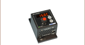
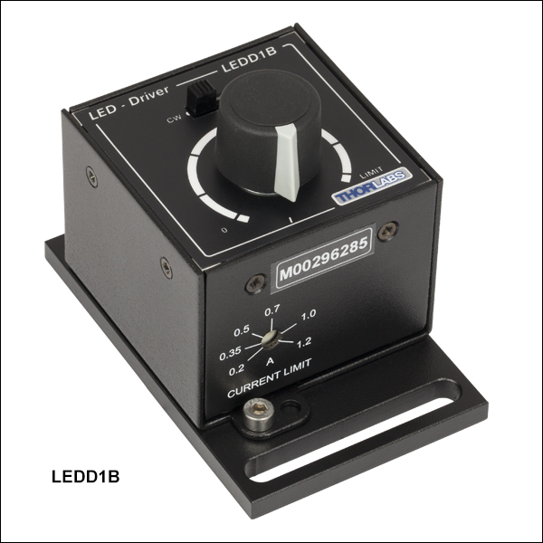
LEDD1B
Power Supply
Sold Separately
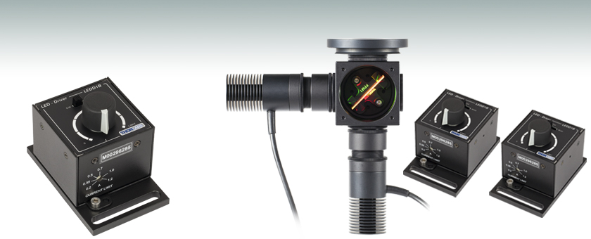
Application Idea
Multiple High-Power LEDs
and Drivers Being Used
in the Same Application


Please Wait
| LED Controller Selection Guide | ||||||
|---|---|---|---|---|---|---|
| Type | Max Number of LEDs |
Max Current |
Modulation Mode |
USB | Remote Operation | Compatible LEDs |
| upLED™ LED Driver |
1 | 1.2 A | - | Yes | Yes | Mounted, Collimated, Fiber Coupled, Diffuse Backlight, and PCB Mounteda |
| Compact T-Cube Driver |
1 | 1.2 A | 0 - 5 kHz | No | No | |
| 4-Channel Driver |
4 | 1 A | 0 - 100 kHz | Yes | Yes | |
| 4.0 A LED Driver | 1 | 4.0 A | 0 - 5 kHz | Yes | Yes | |
| Solis® LED Driver |
1 | 10 A | 0 - 1 kHz | No | No | High Power |
| High-Power Touchscreen Driver |
1 | 10.0 A | 0 - 250 kHz | Yes | Yes | High Power, Mounted, Collimated, Fiber Coupled, Diffuse Backlight, and PCB Mounteda |
Click to Enlarge
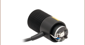
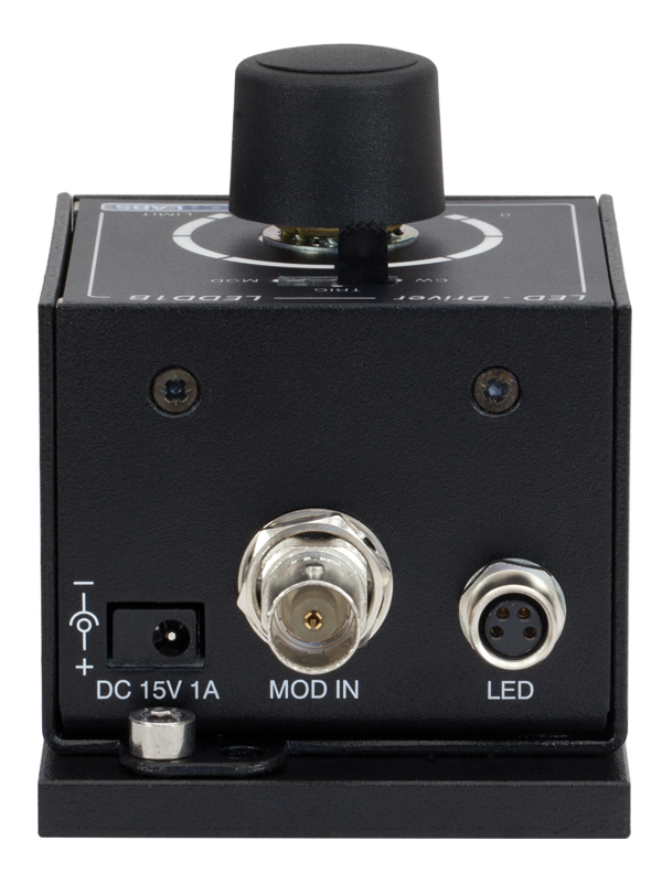
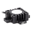
Figure 1.2 Back View of the LEDD1B T-Cube. For more information, please see the Pin Diagrams tab.
| Compact Light Source & Driver Modules |
|---|
| Laser Sources |
| Laser Diode Driver |
| LED Driver |
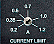
Figure 1.3 Current Limit Adjuster
Features
- Easy-to-Use LED Driver
- 3 Operation Modes:
- Constant Current Mode
- Modulation Mode
- Trigger Mode
- Compact Footprint Measuring: 60 mm x 60 mm x 47 mm (2.4" x 2.4" x 1.8")
- Pulse Width and Frequency Control via External 0 - 5 V Signal
- Adjustable LED Current Limit
- Includes One CAB-LEDD1 Cable (Additional Cables Available Separately Below)
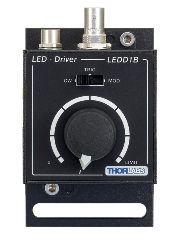
The LEDD1B driver is designed to drive high-power LEDs with currents up to 1200 mA. It features an adjustable LED current limit to protect the connected LED. The output current limit can be adjusted continuously from 0.2 A to 1.2 A using the key slot on the front of the unit (shown in Figure 1.3), thereby ensuring the output current does not exceed the limit regardless of the other settings or the modulation input voltage.
The LEDD1B driver is compatible with our collimated, uncollimated, PCB-mounted, diffuse backlight, and fiber-coupled LEDs, as well as with select unmounted LEDs offered by Thorlabs for which the maximum forward DC current is higher than 200 mA. When driving these LEDs, care must be taken to ensure the LEDD1B current limit is set at or below the LED's maximum forward DC current rating. Set the current limit (see Figure 1.3) by rotating the arrow direction with a flathead screwdriver (one flathead screwdriver is included with each LEDD1B).
The LEDD1B driver offers three operation modes:
- Constant Current Mode: The output current is set between 0 mA and 1200 mA using the knob on the top of the unit. The range of output current controlled by the knob on the top of the unit will rescale to a maximum value set by the current limit.
- Modulation Mode: The output current exactly follows the amplitude and waveform of the voltage input signal, independent of the knob setting on the top of the T-Cube control unit.
- Trigger Mode: The output current switches to the level that has been selected by the knob on the top of the unit as soon as an input voltage threshold is reached. The voltage threshold is fixed and cannot be changed by the user. This mode can be used for pulse width modulation (PWM).
The operation mode can be changed by a switch next to the current selector knob. The trigger and modulation modes are controlled by an external voltage in the 0 to 5 V range.
This LED Driver has the same compact form factor as other T-Cube modules. It is shipped attached to a removable base plate, which allows the T-Cube to be easily secured to an optical table.
Multi-LED Source
A customizable multi-LED source can be constructed using our mounted high-power LEDs and other Thorlabs items. This source may be configured for integration with Thorlabs' flexible SM1 Lens Tube Systems, 30 mm Cage Systems, and microscope adapters. Please see the Multi-LED Source tab for a detailed item list and instructions. Thorlabs also offers integrated, user-configurable 4-Wavelength LED Sources that can be driven using our four-channel LED drivers.
Warning!
The LEDD1B is designed for high-brightness LEDs only. The LED current limit must be adjusted by the trim pot on the front of the unit so that the maximum current of the connected LED will not be exceeded. The available range for this limit is 200 to 1200 mA.
Power Supply Options
The preferred power supply (single channel or hub-based) depends on the end user's application and whether you already own compatible power supplies. To that end and in keeping with Thorlabs' green initiative, we do not ship these units bundled with a power supply. This avoids the cost and inconvenience of receiving an unwanted single-channel supply if a hub-based system would be more appropriate. The power supply options compatible with the LEDD1B LED Driver are listed below.
| Compatible Thorlabs LEDs | |||||
|---|---|---|---|---|---|
| Photo (Click for Link) |
 |
 |
 |
 |
 |
| LED Description | Mounted | Fiber Coupled | Collimated | Diffuse Backlight | PCB Mounteda |
| Specification | Value |
|---|---|
| Common Data | |
| Output Current Range | 0 - 1200 mA |
| LED Current Limit Set Point Range | 200 - 1200 mA |
| LED Forward Voltage | 11 V (Min) 12 V (Typical) |
| Current Ripple | 8 mA |
| Current Ripple Frequency | 570 kHz |
| Modulation Modea,b | |
| Frequency Range | 0 - 5 kHz, Sine Wave |
| Modulation Form | Arbitrary |
| Input Voltage Rate | 0 - 5 V |
| Slew Rate | 13.6 mA/µs |
| Decay Rate | 13.1 mA/µs |
| Trigger Modea | |
| Frequency Range | 0 - 1 kHz |
| Duty Cycle Range | 20 - 80% @ 1 kHz 2 - 98% @ 100 Hz 0.2 - 99.8% @ 10 Hz |
| Modulation Form | Square Wave / PWM |
| Logic Input Levels | TTL Min H-Level: 2 V Max L-Level: 0.55 V |
| Slew Rate | 18 mA/µs |
| Rise Time | 51 µs |
| Decay Rate | 12 mA/µs |
| Fall Time | 79 µs |
| General Data | |
| Power Supply | 15 VDC |
| Maximum Power Consumption | 15 VA |
| Operating Temperature | 0 - 40 °C |
| Storage Temperature | -40 to 70 °C |
| Weight | 240 g |
| Dimensions (W x H x D) | 60 mm x 73 mm x 104 mm |
Modulation In
BNC Female
0 to 5 V external LED control.
LED Connector - Female

Female LED Connector
| Pin | Description |
|---|---|
| 1 | LED Anode |
| 2 | LED Cathode |
| 3 | Unused |
| 4 | Unused |
T-Cube Mounting Options
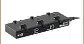
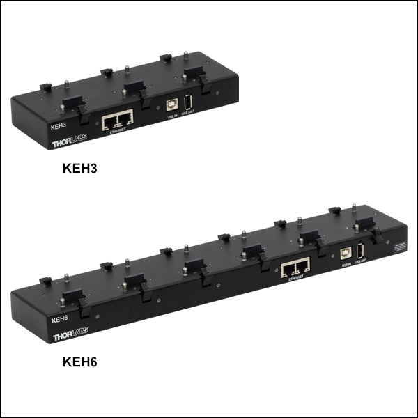
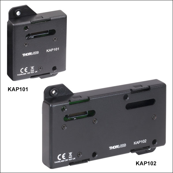
Two options are available to securely mount our T-Cube controllers onto an optical table. An optical table mounting plate, provided with every T-Cube, allows for a single controller to be attached to an optical table. Alternatively, multiple units can be mounted and connected to a single PC by using the KEH3 or KEH6 Controller Hubs. They consist of two parts: the hub, which can support up to three (Item # KEH3) or six (Item # KEH6) T-Cubes or K-Cubes®, and a power supply that plugs into a standard wall outlet. Current- and previous-generation T-Cubes require the previously mentioned mounting plate to be removed and replaced with the KAP101 or KAP102 Adapter Plate, as shown in Video 4.1.
T-Cube and K-Cube Mounting On Controller Hubs
Video 4.1 The controller hubs allow multiple controllers to be connected to one PC for multi-axis applications. K-Cubes can be directly attached to the hub while T-Cubes require a KAP101 or KAP102 Adapter Plate.
Click to Enlarge
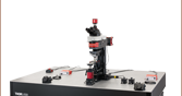
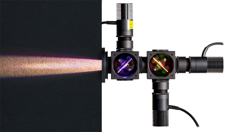
Figure 5.1 Multi-LED Source Coupled to Microscope Illumination Port
Creating a Custom Multi-LED Source for Microscope Illumination
Thorlabs offers the items necessary to create your own custom multi-LED light source using two or three of the mounted LEDs offered below. As configured in the following example, the light source is intended to be used with the illumination port of a microscope. However, it may be integrated with other applications using Thorlabs' versatile SM1 Lens Tube and 30 mm Cage Systems. Thorlabs also offers integrated, user-configurable 4-Wavelength LED Sources.
Design & Construction
First, light will be collimated by lenses mounted in lens tubes. Dichroic mirrors mounted in kinematic cage cubes then combine the output from the multiple LEDs. The mounted LEDs may be driven by LEDD1B Compact T-Cube LED Drivers (power supplies are sold separately). The LEDD1B LED Drivers allow each LED's output to be independently modulated and can provide up to 1200 mA of current. Please take care not to drive the LED sources above their max current ratings.
When designing your custom source, select mounted LEDs from below along with dichroic mirror(s) that have cutoff wavelength(s) between the LED wavelengths. The appropriate dichroic mirror(s) will reflect light from side-mounted LEDs and transmit light along the optical axis. Please note that most of these dichroic mirrors are "longpass" filters, meaning they transmit the longer wavelengths and reflect the shorter wavelengths. To superimpose light from three or more LEDs, add each in series (as shown in Figure 5.1), starting from the back with longer wavelength LEDs when using longpass filters. Shortpass filters may also used if the longer wavelength is reflected and the shorter wavelength is transmitted. Sample combinations of compatible dichroic mirrors and LEDs are offered in Tables 5.4 through 5.6.
It is also necessary to select an aspheric condenser lens for each source with AR coatings appropriate for the source. Before assembling the light source, collimate the light from each mounted LED as detailed in the Collimation tab. For mounting the aspheric lenses in the SM1V05 Lens Tubes using the included SM1RR retaining rings, we recommend the SPW801 Adjustable Spanner Wrench. A properly collimated LED source should have a resultant beam that is approximately homogenous and not highly divergent at a distance of approximately 2 feet (60 cm). An example of a well-collimated beam is shown on the Collimation tab.
After each LED source is collimated, thread the SM1V05 Lens Tubes at the end of each collimated LED assembly into their respective C4W Cage Cube ports using SM1T2 Lens Tube Couplers. Install each dichroic filter in an FFM1 Dichroic Filter Holder, and mount each filter holder onto a B4C Kinematic Cage Cube Platform. Each platform is then installed in the C4W Cage Cubes by partially threading the included screws into the bottom of the cube, and then inserting and rotating the B4C platform into place. Align the platform to the desired position and then firmly tighten the screws. To connect multiple cage cubes and the microscope adapter, use the remaining SM1T2 lens tube couplers along with an SM1L05 0.5" Lens Tube between adjacent cage cubes. Finally, adjust the rotation, tip, and tilt of each B4C platform to align the reflected and transmitted beams so they overlap as closely as possible.
If desired, a multi-LED source may be constructed that employs more than three LEDs. The limiting factors for the number of LEDs that can be practically used are the collimation of the light and the dichroic mirror efficiency over the specified range. Heavier multi-LED sources may be supported with our Ø1" or Ø1.5" Posts.
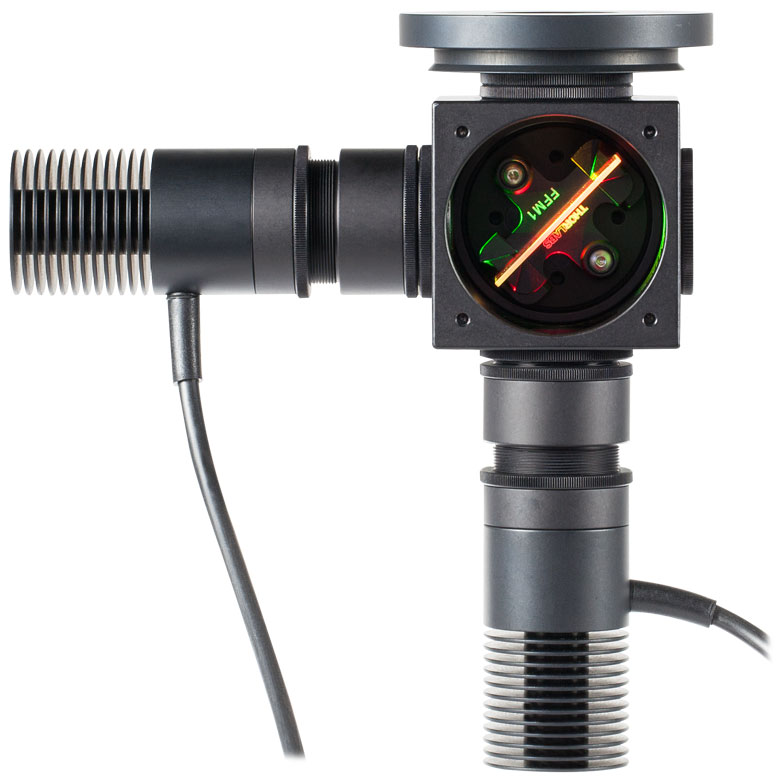
Click to Enlarge
Figure 5.2 Three-LED Source Using Components Mounted LEDs and Dichroic Mirrors
Detailed in Example Configuration 1
| Table 5.3 Parts List | |||||
|---|---|---|---|---|---|
| # | Product Description | Item # | 2 LEDs | 3 LEDs | |
| Item Qty. | |||||
| 1 | Microscope Illumination Port Adapter: |
Olympus IX or BX | SM1A14 | 1 | 1 |
| Leica DMI | SM1A21 | ||||
| Zeiss Axioskop | SM1A23a | ||||
| Nikon Eclipse Ti | SM1A26 | ||||
| 2 | Mounted LEDb | - | 2 | 3 | |
| - | T-Cube LED Driver, 1200 mA Max Drive Current | LEDD1Bc | 2 | 3 | |
| - | 15 V Power Supply Unit for T-Cube | KPS201c | 2 | 3 | |
| 3 | 4-Way Mounting 30 mm Cage Cube | C4W | 1 | 2 | |
| 4 | Kinematic Cage Cube Platform for C4W/C6W | B4C | 1 | 2 | |
| 5 | 30 mm Cage-Compatible Dichroic Filter Mount | FFM1 | 1 | 2 | |
| 6 | Dichroic Filter(s)d | - | 1 | 2 | |
| 7 | Externally SM1-Threaded End Cap | SM1CP2 | 1 | 2 | |
| 8 | SM1 (1.035"-40) Coupler, External Threads, 0.5" Long | SM1T2 | 3 | 5 | |
| 9 | Ø1" SM1 Lens Tube, 1/2" Long External Threads | SM1V05 | 2 | 3 | |
| - | Aspheric Condenser Lens |
AR-Coated 350 - 700 nm | ACL2520U-Ac,e | 2 | 3 |
| AR-Coated 650 - 1050 nm | ACL2520U-Bc,e | ||||
| 10 | SM1 Lens Tube, 0.3" Thread Depth | SM1L03 | 2 | 4 | |
| - | Blank Cover Plate with Rubber O-Ring for C4W/C6W | B1Cc | 1 | 2 | |
Click to Enlarge
Figure 5.7 Beam Profile of Source with 3 Mounted LEDs
Click to Enlarge
Figure 5.8 Two-LED source. This is the same as Example 1, but with the blue LED removed.
| Posted Comments: | |
Yaroslav Sych
(posted 2025-10-03 14:27:54.427) I am using Thorlabs LEDs in fluorescence microscopes. I record changes of fluorescence over time (~1-24h) that is a proxy of my chemical signal. However, either LEDs (eg. M470 , M565 , M405 and M625) or the LED driver (LEDD1B) that is supplying current to the LED are not fully stable over ~24h recording and fluctuate in the range of 1-5% of their power. Is there any way to make these LEDs more stable ? Importantly I drive LEDs in a trigger mode, alternate LEDs (~20 fps), so I can not use a constant power supply that can be more stable. jweimar
(posted 2025-10-06 07:40:29.0) Dear Yaroslav, thank you very much for your feedback! I will contact you directly so we can find a solution. user
(posted 2025-02-14 17:34:20.643) Hello,
We have the following questions regarding the LEDD1B led driver:
1. Does the current limit potentiometer determine the maximum current in
modulation mode (i.e, the LED current when modulation voltage = 5V)?
2. Is the relationship between modulation voltage and the LED current
linear? jjadvani
(posted 2025-02-14 07:32:01.0) Dear User, current limit potentiometer determines the maximum current in modulation. So 0 V represents 0 A current output and 5 V corresponds to max. current output set by potentiometer. And relationship between them is linier. user
(posted 2024-02-19 14:10:53.993) Hello, I am using a TTL sent from our electrophysiology rig to the LED driver. With the shorter fiber optic cable, I cannot get the LED output power above 1.5 mW. So about an 80% drop in power compared to the light output directly from the driver. I need to reach 10 mW power output from the optic cable. Do I need to run a higher voltage input trigger to the driver? (I am currently passing 5 V) hchow
(posted 2024-02-21 05:21:52.0) Dear User, if you are pulsing your LED via the TTL signal modulation input, depending on the frequency and the pulse width, you will probably not get the full optical power of your LED. It will tend to dim a little. However, I would need to know a lot more about your setup before I can determine if there are any problems with it. I will personally reach out to you to discuss your issues. Thank you. user
(posted 2023-07-27 15:19:08.06) Hello. Do you have the some numbers regarding the MTBF or lifetime for the LEDD1B ? Thanks ! hchow
(posted 2023-07-28 08:01:42.0) Dear User, I will personally reach out to you to provide more information. Thank you. user
(posted 2023-04-26 13:58:26.577) Can an non-working LEDD1B be repaired? wskopalik
(posted 2023-04-27 05:34:19.0) Thank you very much for your feedback!
Yes, we can offer repairs for the LEDD1B.
I will contact you directly to arrange the repair. Daewoong Lee
(posted 2023-04-17 10:51:00.563) Hi, I'm Daewoong Lee in South Korea.
I'm trying to use LEDD1B and sentech Vision camera (STC-MCS163U3V). Vision camera can generate output signal. So, I tried to use this signal as trigger signal to turn on LEDD1B in Trigger Mode. But LEDD1B wasn't turned on. This LEDD1B in Trigger Mode is turned on by Power generator.
Do you know what is problem? wskopalik
(posted 2023-04-18 04:36:04.0) Thank you very much for your feedback!
It is possible that the output signal of the camera is either too short or too low to trigger the LEDD1B sufficiently. I could see that the camera outputs a signal of 2.2 V. The LEDD1B needs at least 2 V to be triggered. E.g. if the losses in the connection cable are too high, it is possible that there is not sufficient voltage at the LEDD1B to trigger it.
I will contact you directly so we can find a solution. Mozh k
(posted 2022-04-11 04:09:02.747) Hi
Which device is suitable for curing 3D printed structures and for curing materials that needs to modified with photoinitiators? with the ability to change the wavelength based on nm? Thank you mdiekmann
(posted 2022-04-19 11:51:17.0) Hello and thank you for contacting us! This device is a current driver for our standard LEDs. For curing you might want to take a look at our UV curing systems or at our high power LEDs. As you prefered not to be contacted, please reach out to your local tech support to discuss your application in more detail in order to assist you with this. Wu Yu-Xuan
(posted 2021-09-29 19:52:09.25) Hi, can the LEDD1B drive the laser? soswald
(posted 2021-09-30 08:52:14.0) Dear Wu Yu-Xuan,
thank you for your feedback.
We would recommend our selection of laser drivers instead of the LEDD1B for driving lasers: https://www.thorlabs.de/navigation.cfm?guide_id=112 Wu Yu-Xuan
(posted 2021-09-29 19:49:16.033) Hi, Is it possible to apply sine wave from 0 to 6V at MOD input ,that I select the MOD mode?
Is it possible to apply the 6kHz-sine wave at MOD input ,that I select the MOD mode? soswald
(posted 2021-09-30 03:15:41.0) Dear Wu Yu-Xuan,
thank you for your feedback.
The input voltage range of the LEDD1B modulation is 0 V to 5 V, so 6 V would be too much.
The frequency range for sine wave modulation is 0-5 kHz, so you cannot apply 6 kHz modulation to the modulation input of the LEDD1B. Wu Yu-Xuan
(posted 2021-08-18 18:54:26.967) Hi, Is it possible to apply square wave or triangle wave at MOD input ,that I select the MOD mode? MKiess
(posted 2021-08-20 08:20:54.0) Dear Wu Yu-Xuan, Thank you for your inquiry.
You can apply arbitrary waveforms to the modulation input when you using the driver in modulation mode. user
(posted 2020-11-12 20:51:51.247) Hi, Do you have RoHS 2015/863 information for your LEDD1B ? (Including any exemptions?)
(I see the RoHS 2011/65/EU compliance in the product manual, but no mention of amendment 2015/863.)
Thank you. MKiess
(posted 2020-11-13 07:56:05.0) Thank you very much for your inquiry. You can download the available RoHS certificates of our products under the documents of the corresponding product on our website. I have sent them to you directly. Arthur Ludwigsen
(posted 2020-02-21 18:35:08.223) What is the maximum length of cable that can be used between the M780L3 Mounted LED driven by a LEDD1B Driver? MKiess
(posted 2020-02-26 09:31:51.0) This is a response from Michael at Thorlabs. Thank you very much for your inquiry. We have not made special tests on the maximum length for all possible materials. In general, this depends on what kind of extension cable is used and what kind of connectors are used.
If the internal resistance of the extension becomes too high, additional voltage drops across the extension, which is no longer available to the LED. When the system voltage is exhausted, the LED can no longer be operated at full current. I have contacted you directly to discuss the exact specifications. Yuri Mal
(posted 2019-05-28 13:19:29.67) It is said in specs that for LEDD1B it is required 0 - 5v to modulate LED intensity. My questions are:
1. What current is required to effectively (i.e. to achieve 100% modulation depth) module light intensity?
2. Related to above: what effective load the modulation input would represent for external source?
Thank you in advance for your comments.
Yuri MKiess
(posted 2019-06-04 06:32:59.0) This is a response from Michael at Thorlabs. Thank you very much for your inquiry. The specifications given for the modulation mode depends on the forward voltage and capacitance of the connected LED. Therefore the general procedure to determine the modulation depth is to connect a external voltage source to the MOD IN connector while the output voltage is set to 0V. If the external voltage is increased from 0V to 5V, the brightness of the LED should also increase accordingly. If the external voltage signal is now modulated, the LED is also modulated accordingly.
Regarding the second question, the modulation input impedance is 10kΩ.
I will contact you directly to provide further assistance. jacob.artz
(posted 2019-02-07 11:34:34.853) If we use the LEDD1B to drive a 1.5 A LED, will the LED be damaged? Or merely underpowered by 300 mA?
Thank you. swick
(posted 2019-02-18 03:25:48.0) This is a response from Sebastian at Thorlabs. Thank you for the inquiry.
The 1.5 A LED would be under powered by the LEDD1B. We recommend using the DC2200 for LEDs with high current requirements. user
(posted 2018-10-27 17:14:03.36) Instead of using a bladed chopper, can this driver be used with a square-wave generator 0-5V at the MOD input? Would this enable differential intensity measurements? swick
(posted 2018-11-21 03:22:56.0) This is a response from Sebastian at Thorlabs. Thank you for the inquiry.
It is possible to apply rectangular pulses at MOD input. The resulting shape of the current signal is related to slew- and decay rate of the driver. Differential intensity measurements might be challenging as the LEDD1B can not be accurately set to specific current levels. tmdavies1
(posted 2018-04-13 14:58:19.323) Could this device be powered from a 14.4V 1.8Ah battery? wskopalik
(posted 2018-04-19 04:21:53.0) This is a response from Wolfgang at Thorlabs. Thank you very much for your inquiry.
Generally the LEDD1B can be powered by a battery as well and a voltage of 14.4V would be sufficient. But the specifications of the LEDD1B could change slightly in this case, especially regarding the supported LED forward voltage. Unless your LED needs the full forward voltage range, this would however not be a problem. The forward voltage of most LEDs is much smaller than 11-12V.
The battery would need to be able to provide the necessary current, i.e. it should be rated for more than 1A continuous current. In addition the voltage would need to be stable under load.
I will contact you directly to provide further assistance. utzinger
(posted 2017-11-12 07:25:32.007) What is the type of the power plug connector needed to power up the unit with a custom power supply? E.g. what is the diameter of the central pin? swick
(posted 2017-11-16 03:55:45.0) This is a response from Sebastian at Thorlabs. Thank you for the inquiry. The diameter of the pin is 1.3 mm. I will contact you directly for further assistance. massimo.baroncini
(posted 2017-07-09 23:23:47.383) Can the T-cube driver supply a single LED with a forward voltage of 15 V? In the Spec I don't understand clearly the lowest and highest supported forward voltages. wskopalik
(posted 2017-07-10 02:07:57.0) This is a response from Wolfgang at Thorlabs. Thank you very much for your inquiry.
The LED forward voltage given in the specs of the LEDD1B is the maximum voltage it can supply. So the LEDD1B works up to minimum 11 V, typically 12 V. An LED with 15 V forward voltage couldn't be operated at full power.
I will contact you directly to provide further assistance. joshuamattjackson
(posted 2017-06-27 14:04:14.82) I'd like to push the output current right up to my LED's maximum rating (1 A), but I'm a bit worried of under or overshooting it with the manual pot. Secondly, I'm putting together two identical systems, so I would like to make sure I have both LED's operating with the same current input.
Is there a straightforward way of measuring the pot's resistance or the current output to ensure calibration between two T-cube drivers? Of course, I will check the LED light output for calibration (which is probably a good way of going about it since I doubt two LEDs are exactly the same), but that doesn't help with the under/overshoot problem. Thanks. -Matt wskopalik
(posted 2017-06-29 05:12:03.0) This is a response from Wolfgang at Thorlabs. Thank you very much for your inquiry.
You can set the current limit of the LEDD1B driver on the potentiometer on the front. This will be the maximum current the LEDD1B will provide in CW and trigger mode. To make sure that you stay below a critical current with this setting you could e.g. attach a resistor with a resistance similar to your LED and measure the current going through it. You can use the connection cable CAB-LEDD1 for this. The pin diagrams can be found on the website. Please make sure to take the necessary precautions as the current provided by the LEDD1B is quite high.
The best way to get the same power out of two LEDs is to measure the power emitted by the LEDs and to adjust the currents through the LEDs accordingly. Just like you mentioned two LEDs will never be exactly the same so simply applying the same current wouldn't be enough.
I will contact you directly to provide further assistance. lester
(posted 2017-04-11 17:31:06.313) We have been using flashlamps for many years (since 1976!) to generate 1 ms blue or UV flashes. We typically dump 200 J (!!) into a 75 W xenon short-arc lamp, and we get ~ 100 mJ of photons. The frequency is ~ 0--that is, every 30 s or so.
For most applications, we could focus a laser down to a spot a few microns in dia.
However, for other examples, we need a spot ~ 1mm in dia, which is why we need ~ 100 mJ. Can we do this with LEDs?
10 ms would be OK, too. Your power supply delivers 10 V x 1 A = 10 W, so 100 mW would take 10 ms. However, output light would be much less.
This takes a phone call--not a boilerplate email from your technical department.
Henry A. Lester, Caltech wskopalik
(posted 2017-04-12 03:13:38.0) This is a response from Wolfgang at Thorlabs. Thank you very much for your inquiry.
What you wrote is correct, the main limitation for your application is the light output of the LEDs. Depending on the spectral range in the blue and UV, the LEDs will emit between 10mW and roughly 1000mW. This means that it will take at least 100ms to get 100mJ of energy.
We will contact you directly to talk about your application in more detail. aroy
(posted 2017-01-16 15:32:52.6) Is the BNC only for modulation or can it be used for current control using an arduino etc. swick
(posted 2017-01-17 05:09:25.0) This is a response from Sebastian at Thorlabs. Thank you for the inquiry.
The BNC port can be used for current control from DC - 5 kHz.
DC indicates that the current-level can also be controlled without modulation.
I will contact you directly for further assistance. user
(posted 2014-06-24 17:28:21.56) Can this T-cube driver be used to supply the single LED with forward voltage of 3 V? In the Spec the LED Forward Voltage of 12 V is mentioned. shallwig
(posted 2014-06-27 07:18:34.0) This is a response from Stefan at Thorlabs. Thank you very much for your inquiry. The LEDD1B is a current source which delivers a max output current of 1200mA. You can operate any LED with a forward voltage smaller than 11V with this controller so your LED with 3V will work fine. But you have to take care to set the current limit properly to avoid damaging your LED. Use of LEDs with a forward current lower than 200mA could also result in damage to the LED. sc13967
(posted 2014-03-26 10:33:52.203) For our application, stability of the light source is of the highest importance. Please can you tell me if intensity stability of the LEDs is primarily dictated by the LED itself (we're looking to use the 530 nm LED) or the LED driver. How do the four available LED drivers compare in terms of stability? We were assuming the parameter "current accuracy" will determine stability, is this assumption correct? Thanks, Stephen. tschalk
(posted 2014-03-28 08:16:27.0) This is a response from Thomas at Thorlabs. Thank you very much for your inquiry. We can provide different kinds of drivers. The LEDD1B is a switching driver and shows ripple in the output current which can be as high as 20%. The DC4100 is a linear driver and the main advantages of such a driver is low output current ripple and its EMC compatibility. These drivers are applicable for fluorescence microscopy. The DC2100 is a combination of linear and switching drivers, this method combines the advantage of both principles. A detailed description can be found in the manual of the LEDD1B at section 5.1 LED Driver. The parameter current accuracy does not indicate how stable the drivers are. I will contact you directly with more detailed information. julien
(posted 2010-04-01 11:17:49.0) a response from Julien at thorlabs: We checked and could indeed measure that pulses down to at least 5µs could be obtained with the DC2100 at a rep. rate of 10kHz and for a LED current of 1400mA. julien
(posted 2010-03-19 13:13:46.0) A response from Julien at Thorlabs to Adamt:
when operated in pulsed mode, the LEDD1 has a minimum pulse width of 50µs. We are currently checking if the DC2100 can be brought to achieve 5µs pulses. We will get the test results within one or two weeks. I will contact you directly to discuss the specific details and requirements of your application. adamt
(posted 2010-03-18 21:36:29.0) The ON/OFF time is listed as <25 microseconds. Do you have an idea of the shortest pulse widths possible? I am looking for an about 5 microsecond LED "flash" klee
(posted 2009-07-20 10:14:38.0) Pinout description is now in Overview and selection guide was added to other LED drivers. acable
(posted 2009-07-17 17:47:06.0) I had to search for the pin out diagram for the driver, this is pretty basic information that would best be given on the Overview tab. Also it is hard to understand all the different LED drivers offered by Thorlabs, can you add a selection guide and some links to thread them all together. |
")
 Zoom
Zoom
Click to Enlarge
Figure G1.1 KEH6 Ethernet and USB Controller Hub with Installed T-Cube and K-Cube® Modules
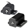
The compact LEDD1B T-Cube is capable of driving high-brightness LEDs with currents up to 1200 mA. The output power can be varied using the manual control knob and modulated using an external trigger signal; the maximum output current is set using an adjuster on the front of the T-Cube. One flathead screwdriver to adjust the current limit and one CAB-LEDD1 connection cable are included with each LEDD1B.
Please note that unlike our other T- and K-Cube® modules, the LEDD1B LED Driver is fully manual. This T-Cube lacks USB connectivity and cannot be controlled via the Kinesis® software.
Power supplies are sold separately; please see the options below.

 Zoom
Zoom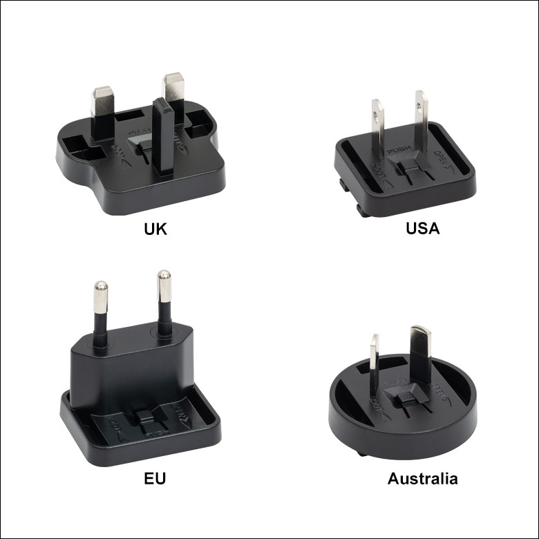
Click for Details
Figure G2.2 Each KPS201 power supply includes one region-specific adapter, which can be selected upon checkout.
Click to Enlarge
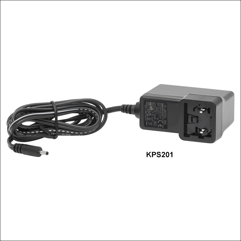
Figure G2.1 The KPS201 Power Supply Unit
- Power Supplies
- KPS201: For K-Cubes® or T-Cubes™ with 3.5 mm Jacks
- Ethernet and USB Controller Hubs Provide Power and Communications
- KEH3: For Up to Three K-Cubes or T-Cubes
- KEH6: For Up to Six K-Cubes or T-Cubes
- KAP101: Adapter Plate for Connecting 60 mm Wide T-Cubes to Hub
- KAP102: Adapter Plate for Connecting 120 mm Wide T-Cubes to Hub
The KPS201 can supply up to 2.66 A and power a single K-Cube or T-Cube. It plugs into a standard wall outlet and provides +15 VDC.
The KEH3 and KEH6 Controller Hubs contain a fully compliant USB 2.0 hub circuit and provide all communications and power distribution for up to three (Item # KEH3) or six (Item # KEH6) K-Cubes or T-Cubes (KAP101 or KAP102 adapters needed for T-Cubes), using only a single power connection. Additionally, the hubs have two Ethernet connection ports. The second Ethernet port or USB OUT port can be connected to the input on another Controller Hub to allow multiple Controller Hub connections while still only requiring a single Ethernet or USB cable from the host PC. The hubs draw a maximum current of 4.6 A; please verify that the cubes being used do not require a total current of more than 4.6 A. Note that the LEDD1B LED Driver does not include USB connectivity and cannot be controlled through the Kinesis® software.
A KAP101 or KAP102 Adapter Plate (sold separately) is required for each T-Cube to operate on the KEH3 or KEH6 controller hubs. The KAP101 is designed to adapt 60 mm wide T-Cubes to the hub, while the KAP102 is designed to adapt 120 mm wide T-Cubes to the hub. Please see the Mounting Options tab for more details.
For more information on the controller hubs, see the full web presentation.

 Zoom
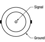
Zoom  Figure 790A Male M8x1 Connector |
Pin | Description | Wire Color |
|---|---|---|---|
| 1 | LED Anode | Brown | |
| 2 | LED Cathode | White | |
| 3 | EEPROM GND | Black | |
| 4 | EEPROM IO | Blue |
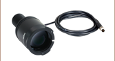
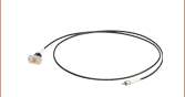
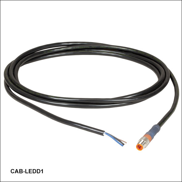
- 4-Pin M8 Connector on One Side
- 4 Bare Wires on Other Side
- 2 m Long, 24 AWG Wires
The 4-Pin M8 connection cable can be used to connect the high-power LEDs on metal core PCB or other custom LEDs to the following Thorlabs LED drivers: LEDD1B, DC40, DC2200, DC4100, and DC4104 (the latter two require the DC4100-HUB).
Pin Connection - Male
Figure 790A shows the male connector for use with the above Thorlabs LED drivers. The connector is a standard M8x1 sensor circular connector. Pins 1 and 2 are the connection to the LED. If using this cable with a non-Thorlabs LED, do not connect anything to the black and blue wires, as this can damage the LED driver. Please note that the pin connection diagram shown here may not be valid for third-party LED drivers.