

Fiber-Coupled Laser Sources: Visible
- SM, MM, and PM Sources Available
- Full Output Powers from 2.5 to 50.0 mW
- Stable, Low Noise, Constant Power Operation
S1FC660
660 nm, 15.0 mW
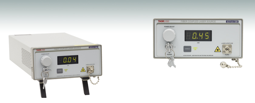
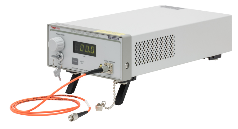
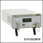
Front Panel Display Provides an Enable Button, Laser Power Control, and Display Screen
OVERVIEW
| Table 1.1 Single Channel Benchtop Laser Sources Selection Guide | |||||
|---|---|---|---|---|---|
| Spectrum | Wavelength | TEC | Laser Type | Cavity Type | Output Fiber Type |
| Visible | 405 - 675 nm | No | Semiconductor | Fabry Perot | SM, MM, or PM |
| 405 - 685 nm | Yes | Semiconductor | Fabry Perot | SM | |
| NIR | 785 - 1550 nm | No | Semiconductor | Fabry Perot | SM or PM |
| 705 - 2000 nm | Yes | Semiconductor | Fabry Perot | SM | |
| 1310 - 1550 nm | Yes | Semiconductor | DFB | SM | |
| 1900 - 2000 nm | N/A | Fiber Laser | Fabry Perot | SM | |
| MIR | 2.7 µm | N/A | Fiber Laser | Fabry Perot | SM |
| Other Fiber-Coupled Laser Sources | |||||
Features
- Available Wavelengths:
- SM: 405 to 675 nm
- MM: 473 nm
- PM: 635 nm
- Single Mode or Multimode FC/PC Fiber Interface
- Power Level is Adjustable via Knob and BNC Modulation Input
- Stable, Low Noise, Constant Power Operation
- Interlock Circuit Provided via 2.5 mm Mono Jack
Thorlabs offers single mode, multimode, and polarization-maintaining fiber-coupled laser sources in the visible spectrum. Each benchtop laser source features both a pigtailed Fabry-Perot laser diode and current controller in a single unit.
The front panel of each laser source displays the output power in mW, an on/off key, and an enable button, and a knob to adjust the laser power. The back panel includes a BNC input that allows the laser diode drive current to be controlled via an external DC or sine wave voltage source and a remote interlock input.
Please refer to Table 1.1 for all of our single channel benchtop laser sources.
| Table 1.2 Key Specificationsa | ||||||||
|---|---|---|---|---|---|---|---|---|
| Item # | S1FC405 | S1FC635 | S1FC637 | S1FC660 | S1FC675 | S1FC473MM | S1FC635PM | |
| Fiber Type | SM | MM | PM | |||||
| Wavelength | 405 nm | 635 nm | 637 nm | 660 nm | 675 nm | 473 nm | 635 nm | |
| Spectrum |  |
 |
 |
 |
- | - | ||
| Full Output Power | 8.0 mW (Min) |
2.5 mW (Min) |
8.0 mW (Min) |
15.0 mW (Min) |
2.5 mW (Min) |
50.0 mW (Max) |
2.5 mW (Min) |
|
| Power Stability | 15 min: ±0.05 dB, 24 hr: ±0.1 dB (After 1 hr Warm-up at 25 ± 10 °C Ambient) |
|||||||


SPECS
| Single Mode Source Specifications | |||||||
|---|---|---|---|---|---|---|---|
| Item # | S1FC405 | S1FC635 | S1FC637 | S1FC660 | S1FC675 | ||
| Wavelength | Minimum | 395 nm | 625 nm | 630 nm | 645 nm | 660 nm | |
| Typical | 405 nm | 635 nm | 637 nm | 660 nm | 675 nm | ||
| Maximum | 415 nm | 640 nm | 645 nm | 665 nm | 680 nm | ||
| Spectruma | |
|
|
|
|||
| Minimum Full Output Power | 8.0 mW | 2.5 mW | 8.0 mW | 15.0 mW | 2.5 mW | ||
| Setpoint Resolution | 0.01 mW | 0.01 mW | 0.01 mW | 0.01 mW | 0.01 mW | ||
| Laser Class | 3B | 3R | 3B | 3B | 3R | ||
| Fiber | |||||||
| Fiber Type | S405-XP | SM600 | SM600 | SM600 | SM600 | ||
| Mode Field Diameterb | 3.3 µm @ 405 nm | 3.6 - 5.3 µm | 3.6 - 5.3 µm | 3.6 - 5.3 µm | 3.6 - 5.3 µm | ||
| Numerical Aperture | 0.12 | 0.10 - 0.14 | 0.10 - 0.14 | 0.10 - 0.14 | 0.10 - 0.14 | ||
| Output Fiber Connector | FC/PC, Wide 2.1 mm Key Compatible | ||||||
| Electrical | |||||||
| Power Stability | 15 min: ±0.05 dB, 24 hr: ±0.1 dB (After 1 hr Warm-Up at 25 ± 10 °C Ambient) |
||||||
| Display Accuracy | ±10% | ||||||
| Adjustment Range | ~0 mW to Full Power | ||||||
| Input Power | 115 VAC / 230 VAC (Switch Selectable) 50 - 60 Hz | ||||||
| Modulation Input | 0 - 5 V = 0 - Full Power, DC or Sine Wave Input Only | ||||||
| Modulation Bandwidth |
5 kHz Full Depth of Modulation 30 kHz Small Signal Modulation |
||||||
| Environmental | |||||||
| Operating Temperature | 15 to 35 °C | ||||||
| Storage Temperature | 0 to 50 °C | ||||||
| Multimode Source Specifications | |
|---|---|
| Item # | S1FC473MM |
| Wavelength | 473 nm |
| Maximum Output Powera | 50.0 mW |
| Stability | 15 min: ±0.05 dB, 24 hr: ±0.1 dB (After 1 hr Warm-Up at 25 ± 10 °C Ambient) |
| Display Accuracy | ±10 % |
| Setpoint Resolution | 0.1 mW |
| Adjustment Range | ~0 mW to Full Power |
| AC Input | 115 / 230 VAC (Switch Selectable) 50 - 60 Hz |
| Modulation Input | 0 - 5 V = 0 - Full Power, DC or Sine Wave Input Only |
| Modulation Bandwidth | 5 kHz Full Depth of Modulation 30 kHz Small Signal Modulation |
| Fiber | FG105UCA |
| Environmental | |
| Operating Temperature | 15 to 35 °C |
| Storage Temperature | 0 to 50 °C |
| Polarization-Maintaining Source Specifications | ||||
|---|---|---|---|---|
| Item # | S1FC635PM | |||
| Wavelengtha | 635 nm | |||
| Minimum Full Output Power | 2.5 mW | |||
| Stability | 15 min: ±0.05 dB, 24 hr:±0.1 dB (After 1 hr Warm-Up at 25 ± 10 °C Ambient) |
|||
| Display Accuracy | ±10% | |||
| Setpoint Resolution | 0.01 mW | |||
| Adjustment Range | ~0 mW to Full Power | |||
| Minimum Polarization Extinction Ratio | 15 dB | |||
| Environmental | ||||
| Operating Temperature | 15 to 35 °C | |||
| Storage Temperature | 0 to 50 °C | |||
| AC Input | 115 VAC / 230 VAC (Switch Selectable) 50 - 60 Hz | |||
| Modulation Input | 0 - 5 V = 0 - Full Power, DC or Sine Wave Input Only | |||
| Modulation Bandwidth | 5 kHz Full Depth of Modulation 30 kHz Small Signal Modulation |
|||
| Fiber | PM630-HP | |||
PIN DIAGRAMS
Modulation In
BNC Female
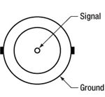
0 to 5 V Max, 50 Ω
Remote Interlock Input
2.5 mm Mono Jack
Terminals must be shorted either by included plug or user device, i.e. external switch, for laser mode "ON" to be enabled.
LASER SAFETY
Laser Safety and Classification
Safe practices and proper usage of safety equipment should be taken into consideration when operating lasers. The eye is susceptible to injury, even from very low levels of laser light. Thorlabs offers a range of laser safety accessories that can be used to reduce the risk of accidents or injuries. Laser emission in the visible and near infrared spectral ranges has the greatest potential for retinal injury, as the cornea and lens are transparent to those wavelengths, and the lens can focus the laser energy onto the retina.
 |
 |
 |
 |
 |
 |
 |
 |
 |
Safe Practices and Light Safety Accessories
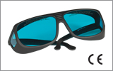
- Laser safety eyewear must be worn whenever working with Class 3 or 4 lasers.
- Regardless of laser class, Thorlabs recommends the use of laser safety eyewear whenever working with laser beams with non-negligible powers, since metallic tools such as screwdrivers can accidentally redirect a beam.
- Laser goggles designed for specific wavelengths should be clearly available near laser setups to protect the wearer from unintentional laser reflections.
- Goggles are marked with the wavelength range over which protection is afforded and the minimum optical density within that range.
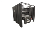
- Laser Safety Curtains and Laser Safety Fabric shield other parts of the lab from high energy lasers.
- Blackout Materials can prevent direct or reflected light from leaving the experimental setup area.
- Thorlabs' Enclosure Systems can be used to contain optical setups to isolate or minimize laser hazards.
- A fiber-pigtailed laser should always be turned off before connecting it to or disconnecting it from another fiber, especially when the laser is at power levels above 10 mW.
- All beams should be terminated at the edge of the table, and laboratory doors should be closed whenever a laser is in use.
- Do not place laser beams at eye level.
- Carry out experiments on an optical table such that all laser beams travel horizontally.
- Remove unnecessary reflective items such as reflective jewelry (e.g., rings, watches, etc.) while working near the beam path.
- Be aware that lenses and other optical devices may reflect a portion of the incident beam from the front or rear surface.
- Operate a laser at the minimum power necessary for any operation.
- If possible, reduce the output power of a laser during alignment procedures.
- Use beam shutters and filters to reduce the beam power.
- Post appropriate warning signs or labels near laser setups or rooms.
- Use a laser sign with a lightbox if operating Class 3R or 4 lasers (i.e., lasers requiring the use of a safety interlock).
- Do not use Laser Viewing Cards in place of a proper Beam Trap.
Laser Classification
Lasers are categorized into different classes according to their ability to cause eye and other damage. The International Electrotechnical Commission (IEC) is a global organization that prepares and publishes international standards for all electrical, electronic, and related technologies. The IEC document 60825-1 outlines the safety of laser products. A description of each class of laser is given below:
| Class | Description | Warning Label |
|---|---|---|
| 1 | This class of laser is safe under all conditions of normal use, including use with optical instruments for intrabeam viewing. Lasers in this class do not emit radiation at levels that may cause injury during normal operation, and therefore the maximum permissible exposure (MPE) cannot be exceeded. Class 1 lasers can also include enclosed, high-power lasers where exposure to the radiation is not possible without opening or shutting down the laser. |  |
| 1M | Class 1M lasers are safe except when used in conjunction with optical components such as telescopes and microscopes. Lasers belonging to this class emit large-diameter or divergent beams, and the MPE cannot normally be exceeded unless focusing or imaging optics are used to narrow the beam. However, if the beam is refocused, the hazard may be increased and the class may be changed accordingly. |  |
| 2 | Class 2 lasers, which are limited to 1 mW of visible continuous-wave radiation, are safe because the blink reflex will limit the exposure in the eye to 0.25 seconds. This category only applies to visible radiation (400 - 700 nm). |  |
| 2M | Because of the blink reflex, this class of laser is classified as safe as long as the beam is not viewed through optical instruments. This laser class also applies to larger-diameter or diverging laser beams. |  |
| 3R | Class 3R lasers produce visible and invisible light that is hazardous under direct and specular-reflection viewing conditions. Eye injuries may occur if you directly view the beam, especially when using optical instruments. Lasers in this class are considered safe as long as they are handled with restricted beam viewing. The MPE can be exceeded with this class of laser; however, this presents a low risk level to injury. Visible, continuous-wave lasers in this class are limited to 5 mW of output power. |  |
| 3B | Class 3B lasers are hazardous to the eye if exposed directly. Diffuse reflections are usually not harmful, but may be when using higher-power Class 3B lasers. Safe handling of devices in this class includes wearing protective eyewear where direct viewing of the laser beam may occur. Lasers of this class must be equipped with a key switch and a safety interlock; moreover, laser safety signs should be used, such that the laser cannot be used without the safety light turning on. Laser products with power output near the upper range of Class 3B may also cause skin burns. |  |
| 4 | This class of laser may cause damage to the skin, and also to the eye, even from the viewing of diffuse reflections. These hazards may also apply to indirect or non-specular reflections of the beam, even from apparently matte surfaces. Great care must be taken when handling these lasers. They also represent a fire risk, because they may ignite combustible material. Class 4 lasers must be equipped with a key switch and a safety interlock. |  |
| All class 2 lasers (and higher) must display, in addition to the corresponding sign above, this triangular warning sign. |  |
|
Single Mode Fiber-Coupled Laser Sources
- Five Wavelengths Available from 405 to 675 nm
- Single Mode, FC/PC Fiber Interface
- Minimum Full Output Powers of Up to 15.0 mW
- Fiber Patch Cables Sold Separately
- Custom Wavelengths Available; Contact Tech Sales
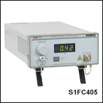
These Single Mode Fiber-Coupled Laser Sources conveniently package a pigtailed Fabry-Perot laser diode and current controller into a single benchtop unit. The Fabry-Perot laser diode inside each unit is pigtailed to a single mode fiber that is terminated at an FC/PC bulkhead (wide and narrow key compatible) attached to the front panel of the unit. Thorlabs offers single mode fiber optic patch cables for connecting to the bulkhead on the front panel. To minimize losses, we recommend using a fiber patch cable that is the same fiber type as the fiber-pigtailed laser; refer to the Specs tab for the internal fiber type used for the pigtail. Additionally, to reduce noise from back reflections, we recommend that a hybrid FC/PC to FC/APC cable be used with the FC/PC end connected to the laser source.
Also found on the front panel is a display that shows the output power in mW, an on/off key, an enable button, and a knob to adjust the laser power. The back panel includes an input that allows the laser diode drive current to be controlled via an external DC or sine wave voltage source and a remote interlock input.
Note: The laser must be off when connecting or disconnecting fibers from the device, particularly for power levels above 10 mW.
For applications using a 635 nm source, Thorlabs also offers a compact fiber-coupled laser source with a USB interface. For optogenetics applications, Thorlabs offers a 473 nm benchtop laser source below that incorporates multimode fiber. For a polarized output, laser sources that incorporate polarization-maintaining fiber are also available below. For telecom applications that require tunable output, please see our benchtop tunable telecom laser sources. For laser sources with custom wavelengths or with an FC/APC fiber interface, please contact Tech Sales.
Part Number | Description | Price | Availability |
|---|---|---|---|
S1FC405 | Fabry-Perot Benchtop Laser Source, 405 nm, 8.0 mW, FC/PC | $2,118.89 | Today |
S1FC635 | Fabry-Perot Benchtop Laser Source, 635 nm, 2.5 mW, FC/PC | $1,780.78 | In Stock Overseas |
S1FC637 | Fabry-Perot Benchtop Laser Source, 637 nm, 8.0 mW, FC/PC | $1,949.83 | Today |
S1FC660 | Fabry-Perot Benchtop Laser Source, 660 nm, 15.0 mW, FC/PC | $1,937.12 | Today |
S1FC675 | Fabry-Perot Benchtop Laser Source, 675 nm, 2.5 mW, FC/PC | $1,820.19 | Today |
Multimode Fiber-Coupled Laser Source
- Output Wavelength: 473 nm
- Multimode FC/PC Fiber Interface
- 50.0 mW Power Output
- Fiber Patch Cables Sold Separately
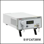
The S1FC473MM Fiber-Coupled Laser provides 50.0 mW of output power and a wavelength of 473 nm, making it an ideal source for many Optogenetics applications. It includes a pigtailed FP laser diode and current controller in a single benchtop unit. The unit's output can also be externally modulated at 5 kHz full depth/30 kHz small signal. The output is a FG105UCA multimode fiber terminated at an FC/PC connector. The unit is compatible with our extensive line of multimode patch cables and optogenetics equipment.
The front panel includes a display that shows the output power in mW, an on/off key, an enable button, and a knob to adjust the laser power. The back panel includes an input that allows the laser diode drive current to be controlled via an external voltage source and a remote interlock input. For complete operating instructions, please refer to the manual, available by clicking the red Docs icon ( ) below.
Note: The laser must be off when connecting or disconnecting fibers from the device, particularly for power levels above 10 mW.
We also offer fiber-coupled LEDs as well as other fiber-coupled laser sources.
Part Number | Description | Price | Availability |
|---|---|---|---|
S1FC473MM | Customer Inspired! Fiber-Coupled Laser Source, 473 nm, 50.0 mW, MM Fiber, FC/PC | $8,854.13 | Today |
Polarization-Maintaining Fiber-Coupled Laser Source
- Output Wavelength: 635 nm
- Single Mode Polarization-Maintaining FC/PC Fiber Interface
- Minimum Full Output Power of 2.5 mW
- Fiber Patch Cables Sold Separately
- Slow Axis of the PM Fiber Aligned to the Narrow Key of the FC/PC Bulkhead Connector
- Custom Visible Wavelengths Available; Contact Tech Sales
These Polarization-Maintaining Fiber-Coupled Laser Sources package a pigtailed Fabry-Perot laser diode inside each benchtop unit. The laser diode is pigtailed to a single mode PM fiber that is terminated at an FC/PC bulkhead attached to the front panel of the unit. During the pigtailing process, the fiber alignment is actively maintained so that the polarization axis of the laser diode is aligned with the slow-axis of the PM fiber. In addition, the slow-axis of the PM fiber is aligned to the narrow key of the FC/PC bulkhead connector on the front panel of the benchtop unit. Thorlabs offers polarization-maintaining fiber optic patch cables for connecting to the bulkhead on the front panel. To minimize losses, we recommend using a fiber patch cable that is the same fiber type as the fiber-pigtailed laser; refer to the Specs tab for the internal fiber type used for the pigtail. Additionally, to reduce noise from back reflections, we recommend that a hybrid FC/PC to FC/APC cable be used with the FC/PC end connected to the laser source.
Also found on the front panel is a display that shows the output power in mW, an on / off key, an enable button, and a knob to adjust the laser power. The back panel includes an input that allows the laser diode drive current to be controlled via an external voltage source and a remote interlock input.
Note: The laser must be off when connecting or disconnecting fibers from the device.
Part Number | Description | Price | Availability |
|---|---|---|---|
S1FC635PM | Fiber-Coupled Laser Source, 635 nm, 2.5 mW, PM Fiber, FC/PC | $2,354.00 | Today |