

CMOS Camera Beam Profilers
- 245 - 400 nm or 350 - 1100 nm Wavelength Range
- Beam Diameter: 20 µm to 7.0 mm or 10.0 mm
- For Continuous Wave, Pulsed Beams, and Single Pulses
- M2 Measurement with Optional Extension Set
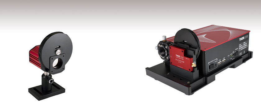
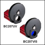
BC207UV
Filter Wheel with 6 Neutral Density Filters Included
(Post and Post Holder Sold Separately)
Application Idea
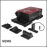
Use the BC210CV/M with the
M2MS M2 Extension Set to create a
complete beam quality measurement system.
OVERVIEW
| Table 1.1 Key Specifications | ||||
|---|---|---|---|---|
| Item # | BC207UV(/M) | BC207VIS(/M) | BC210CU(/M) | BC210CV(/M) |
| Wavelength Range | 245 - 400 nma | 350 - 1100 nm | 245 - 400 nma | 350 - 1100 nm |
| Power Range | 20 fW - 1 Wb | 40 fW - 1 Wc | 20 fW - 1 Wb | 40 fW - 1 Wc |
| Beam Diameter | 20 µm - 7.0 mm | 20 µm - 10.0 mm | ||
| Compatible Light Sources | CW, Pulsedd | |||
| Sensor Size | 8.45 mm x 7.07 mm | 14.13 mm x 10.32 mm | ||
| Resolution | 5.0 MP | 12.3 MP | ||
Features
- Full 2D Analysis of Continuous Wave or Pulsed Laser Beam Profiles
- High Resolution:
- 2448 x 2048 Pixels (BC207 Series)
- 4096 x 2992 Pixels (BC210C Series)
- Low Noise: Signal-to-Noise Ratio ≤ 71 dB
- 12-Bit CMOS Camera
- Large Sensor Area for Uniformity and Linearity (See Sensor Size in Table 1.1)
- Window Protects Sensor from Dust
- Integrated Filter Wheel with Six Neutral Density Filters
- User-Calibratable Power Readout
- Exposure Time: 27 µs to 1 s (BC207 Series) or 25 µs to 500 ms (BC210C Series)
- Gain Control from 0 to 12 dB
- Black Level and Ambient Light Compensation
- External Trigger Input
- Optional M² Extension Kit for Automated M² Analysis (See Below)
Thorlabs' Camera-Based Beam Profilers allow complex mode patterns (like flat top and donut) to be identified while optimizing a laser system. Compared to scanning slit beam profilers, camera beam profilers can capture a more detailed beam profile and provide a true 2D analysis of the beam's power density distribution.
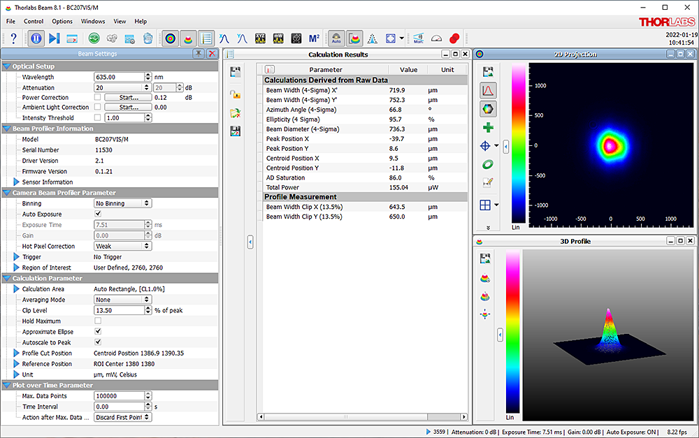
Click to Enlarge
Figure 1.2 One Possible Configuration of the Beam Software GUI Showing Beam Settings, Calculation Results, 2D Projection, and 3D Profile.
These beam profilers are suited for use with either continuous wave or pulsed sources. Several trigger modes allow flexible capturing of single pulses, including a TTL input for triggered single pulse detection of signals with repetition rates up to 37 kHz; see the manual for more information.
The automatic dark level calibration provides very stable dark currents independent of the device settings, eliminating the need to recalibrate the dark level for each user setting.
An integrated filter wheel with 6 high-quality neutral density (ND) filters allows the profiler to be adapted for use with beam intensities from nanowatts to 1 W (see the Specs and ND Filter tabs for details). Engraved labels are included on the filter wheel to indicate the ND filter pre-installed in each slot. If filters need to be removed or replaced, the wheel can be opened using a flathead screwdriver (see the manual for more information on removing filters).
Each filter housing is internally SM1 (1.035"-40) threaded for easy integration with Thorlabs' lens tube systems and mounts for other optical components such as additional attenuation filters. Both BC207 and BC210C Series Beam Profilers have 1/4"-20 (M6 x 1.0 mm) tapped holes for post mounting and attachment to an M2MS series M2 measurement system.
The integrated power meter can be user calibrated and is perfectly suited for simultaneous power and beam shape optimization without the need for an external power meter. A measured mean value of the ambient light intensity is subtracted from the beam profile measurement so as to compensate for ambient light. The automatic exposure and gain control feature adapts the camera settings to the actual beam intensity. The USB 3.0 interface allows up to 4 or 1.5 full frames per second at full resolution for the BC207 series or BC210C series, respectively. Measurements at higher frame rates can be achieved and transferred with reduced frame sizes.
The BC207 series and BC210C series camera beam profilers utilize Thorlabs' Beam software package, which can be downloaded via the links on the Software tab. Features of the software package are listed under the User Interface tab. Driver information, file locations, and reference notes for interfacing with our beam profilers using LabVIEW™, C, Visual C#, and Python are available in the user manual, which can be found by clicking on the red Docs icon (![]() ) next to the item number below. The BC207 series is compatible with software version 8.0 or higher while the BC210C series is compatible with software version 9.0 or higher.
) next to the item number below. The BC207 series is compatible with software version 8.0 or higher while the BC210C series is compatible with software version 9.0 or higher.
Extension sets are available below to convert these camera beam profilers into a fully-automated M² measurement system. Thorlabs also offers a scanning slit beam profiler, as well as complete M² analysis systems with included beam profilers.
SPECS
| Item # | BC207UV(/M) | BC210CU(/M) | BC207VIS(/M) | BC210CV(/M) |
|---|---|---|---|---|
| Wavelength Range | 245 - 400 nma | 350 - 1100 nm | ||
| Power Range | 20 fW - 1 Wb,c | 40 fW - 1 Wc,d | ||
| Beam Diameter | 20 µm - 7.0 mm | 20 µm - 10.0 mm | 20 µm - 7.0 mm | 20 µm - 10.0 mm |
| Compatible Light Sources | CW, Pulsede | |||
| Protective Glass | WG41010-UV | NG3 Absorptive ND Filter, Ø25 mm, 1 mm Thick, Nominal Optical Density: 1.0 |
||
| Absorptive Neutral Density Filters | ||||
| Nominal Values | 20 dB, 30 dB, 40 dBf | 20 dB, 40 dB, 60 dB (Two Sets)g | ||
| AR Coating Wavelength Range | N/A | 350 - 700 nm (Three Filters) | ||
| 650 - 1050 nm (Three Filters) | ||||
| Reflective Neutral Density Filters | ||||
| Nominal Attenuation Values | 20 dB, 30 dB, 40 dB | N/A | ||
| Sensor | ||||
| Chip | 5.0 MP Sony IMX264LLR, 11.1 mm Diagonal, Windowless |
12.3 MP Sony IMX304LLR, 17.5 mm Diagonal, Windowless |
5.0 MP Sony IMX264LLR, 11.1 mm Diagonal, Windowless |
12.3 MP Sony IMX304LLR, 17.5 mm Diagonal, Windowless |
| Aperture Size (Max) | 8.45 mm x 7.07 mm | 14.13 mm x 10.32 mm | 8.45 mm x 7.07 mm | 14.13 mm x 10.32 mm |
| Pixel Size | 3.45 µm x 3.45 µm | |||
| Resolution (Max) | 2448 x 2048 pixel, ROI Selectable | 4096 x 2992 pixel, ROI Selectable | 2448 x 2048 pixel, ROI Selectable | 4096 x 2992 pixel, ROI Selectable |
| Camera | ||||
| Shutter | Global | |||
| Binning | 1 x 1; 2 x 2; 4 x 4; 8 x 8; 16 x 16 | |||
| Frame Rate (Max) @ Full Resolution | 4 fpsh | 1.5 fpsh | 4 fpsh | 1.5 fpsh |
| Frame Rate @ 1224 x 1024 Pixels | >8 fpsh | |||
| Frame Rate @ 612 x 512 Pixels | >12 fpsh | |||
| Pulse Frequency | Up to 37 kHz (Single Pulse Detection), Unlimited (Multi-Pulse Detection)i |
|||
| Image Digitization | 12 Bit | |||
| Signal-to-Noise Ratio | ≤71 dB | |||
| Exposure Range | 27 µs - 1 s | 25 µs - 500 ms | 27 µs - 1 s | 25 µs - 500 ms |
| Gain Range | 0 to 12 dB | |||
| Image Capture Modes | Single Frame, Continuous, Hardware Triggered | |||
| Sensor Distance to Front Filter Holder Surface |
20.7 mm (0.82") | 20.3 mm (0.80") | 20.7 mm (0.82") | 20.3 mm (0.80") |
| Interfaces | ||||
| Trigger Input | TTL Level, LVTTL Compatible, BNC Jack, Low: 0 to +0.4 V; High: 2.4 V to 5.5. Vj |
TTL Level, LVTTL Compatible, SMA Jack, Low: 0 to +0.4 V; High: 2.4 V to 5.5. Vj |
TTL Level, LVTTL Compatible, BNC Jack, Low: 0 to +0.4 V; High: 2.4 V to 5.5. Vj |
TTL Level, LVTTL Compatible, SMA Jack, Low: 0 to +0.4 V; High: 2.4 V to 5.5. Vj |
| Trigger Delay | 0.27 µs | |||
| Pulse Width | 100 µs (Min) | |||
| PC Interface | USB 3.0 (Micro-B) | USB 3.0 (Right Angle Micro-B) | USB 3.0 (Micro-B) | USB 3.0 (Right Angle Micro-B) |
| General | ||||
| Operating Temperature | 10 to 35 °C | |||
| Storage Temperature | 0 to 55 °C | |||
| Size (H x W x D) Incl. Filter Wheel | 94.3 mm x 84.8 mm x 85.7 mm (3.71'' x 3.34'' x 3.37'') |
95.8 mm x 88.4 mm x 34.7 mm (3.77'' x 3.48'' x 1.37'') |
94.3 mm x 84.8 mm x 85.7 mm (3.71'' x 3.34'' x 3.37'') |
95.8 mm x 88.4 mm x 34.7 mm (3.77'' x 3.48'' x 1.37'') |
| Weight | 420 g | 300 g | 420 g | 300 g |
| Mounting Holes | Imperial: 1/4"-20; Metric: M6 x 1.0 mm | |||
| Power Supply | 3.6 W, USB Bus Powered | 3.9 W, USB Bus Powered | 3.6 W, USB Bus Powered | 3.9 W, USB Bus Powered |
| Included Cable for PC Interface | USB 3.0 A to Micro-B (3 m Length) | USB 3.0 A to Right-Angle Micro-B (3 m Length) |
USB 3.0 A to Micro-B (3 m Length) | USB 3.0 A to Right-Angle Micro-B (3 m Length) |
Click to Enlarge
Figure 2.1 The operating power range depends on the beam diameter, the selected optical filter, and the wavelength. For example, the blue-dashed lines show the minimum and maximum powers that the BC207UV profiler with a 40 dB ND filter can detect for a 400 nm source that has a beam diameter between 20 µm and 7 mm. Note that the neutral density filter will begin to heat up and can be damaged if exposed to incident powers above 1 W for more than a few seconds.
Click to Enlarge
Figure 2.2 The operating power range depends on the beam diameter, the selected optical filter, and the wavelength. For example, the blue-dashed lines show the minimum and maximum powers that the BC210CU profiler with a 40 dB ND filter can detect for a 400 nm source that has a beam diameter between 20 µm and 7 mm. Note that the neutral density filter will begin to heat up and can be damaged if exposed to incident powers above 1 W for more than a few seconds.
Click to Enlarge
Figure 2.3 This graph shows the relative reponse curves of the BC207 and BC210C Series Beam Profilers without the use of an ND filter. The blue-shaded region marks the specified operating wavelength range for Item #s BC207UV and BC210CU, while the pink-shaded region is this range for Item #s BC207VIS and BC210CV.
ND FILTERS
Neutral Density Filters
BC207UV(/M) and BC210CU(/M) Camera Beam Profilers
The BC207UV(/M) and BC210CU(/M) beam profilers each come with six neutral density filters, of which three are absorptive and three are reflective, to cover the 245 nm to 400 nm operating wavelength range. Since the BC207UV and BC210CU cameras are also sensitive to short wavelength visible light (see the relative response curve on the Specs tab), three absorptive ND filters are included for use near the 400 nm upper limit of the specified wavelength range.
Click to Enlarge
Click for Raw Data
Figure 3.2 This graph shows the filter attenuation with respect to wavelength for the three absorptive filters included with the BC207UV(/M) or BC210CU(/M) beam profiler. These filters are recommended for use near the 400 nm upper limit of the BC207UV(/M) and BC210CU(/M) profilers' operating wavelength range.
Click to Enlarge
Click for Raw Data
Figure 3.1 This graph shows the filter attenuation with respect to wavelength for the three reflective filters included with the BC207UV(/M) or BC210CU(/M) beam profiler.
| ND Filters Included with BC207UV(/M) and BC210CU(/M) Profilers |
|||
|---|---|---|---|
| Item # | Type | Wavelength Range |
Nominal Filter Attenuation |
| NDUV20B | Reflective | 200 to 1200 nm | 20 dB |
| NDUV30B | 30 dB | ||
| NDUV40B | 40 dB | ||
| NE20B | Absorptivea | 400 to 650 nm | 20 dB |
| NE30B | 30 dB | ||
| NE40B | 40 dB | ||
BC207VIS(/M) and BC210CV(/M) Camera Beam Profilers
The BC207VIS(/M) and BC210CV(/M) beam profilers each come with six absorptive ND filters to cover the 400 nm to 1100 nm wavelength operating range. The filters have an AR coating deposited on both sides, with one set coated for the 350 to 700 nm range and the other coated for the 650 to 1050 nm range.
Click to Enlarge
Click for Raw Data
Figure 3.4 This graph shows the filter attenuation with respect to wavelength for the three B-coated filters included with the BC207VIS(/M) or BC210CV(/M) beam profiler. The wavelength range of this AR coating covers 650 nm to 1050 nm, which is indicated by the blue shaded region.
Click to Enlarge
Click for Raw Data
Figure 3.3 This graph shows the filter attenuation with respect to wavelength for the three A-coated filters included with the BC207VIS(/M) or BC210CV(/M) beam profiler. The wavelength range of this AR coating covers 350 nm to 700 nm which is indicated by the blue shaded region.
| ND Filters Included with BC207VIS(/M) and BC210CV(/M) Profilers |
|||
|---|---|---|---|
| Item # | Type | AR Coating Wavelength Range |
Nominal Filter Attenuation |
| NE20B-A | Absorptive | 350 to 700 nm | 20 dB |
| NE40B-A | 40 dB | ||
| NE60B-A | 60 dB | ||
| NE20B-B | 650 to 1050 nm | 20 dB | |
| NE40B-B | 40 dB | ||
| NE60B-B | 60 dB | ||
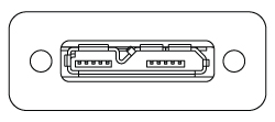
PIN DIAGRAMS
BC207 and BC210C Series CMOS Camera Beam Profilers
Computer Connection
for BC207 and BC210C Series
USB 3.0 Micro B Connector
Trigger Input for BC210C Series
SMA Female
Do not exceed input voltages between 0.0 V to +5.5 V.
Input Impedance > 100 kΩ
Trigger Input for BC207 Series
BNC Female
Do not exceed input voltages between 0.0 V to +5.5 V.
Input Impedance > 100 kΩ
M2MS(-AL) Extension Sets
Computer Connection
USB 2.0
A USB 2.0 Mini-B to A cable is included with each extension kit.
Optional Connection
USB 2.0
Two USB 2.0 Type A ports are included for connecting the slit beam profilers and one other device, such as the TSP01 USB temperature and humidity controller. The BC207 and BC210C Beam Profilers require USB 3.0 and should not be connected to these ports.
DC Power Supply
15 V / 3 A AC Adapter with a 5.5 mm Outer Diameter DC Connector
Alignment Laser
3.5 mm Mono Jack

USER INTERFACE
Main Window

Click to Enlarge
Figure 5.1 The main window of the GUI includes the menu bar, tool bar, status bar, and a frame where several windows can be displayed. This screenshot includes several panels: Beam Settings, Calculation Results, 2D Projection, and 3D Profile. The Beam Settings Panel displays all important information in a single location; this panel can be unpinned from the main window and moved to a second location, such as another monitor.
Thorlabs Beam Software for the BC207 and BC210C Series Beam Profilers
- GUI with Adjustable Layout: Windows with Different Measurement Results
can be Rearranged and Resized within the Workspace - 2D and 3D Views of the Beam Profile
- Selectable Overlays such as Peak, Centroid, and Cut Profiles
- 3D View is Fully Rotatable
- M² and Divergence Measurements Compliant with ISO 11146
- Data Export:
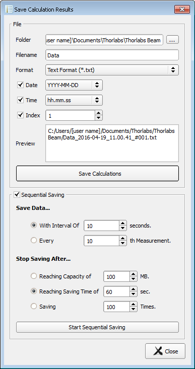
- Results can be Exported from Windows in Different Formats
- Sequential Saving
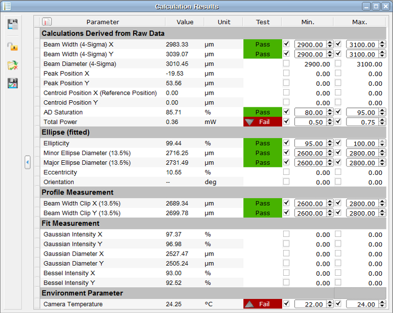
- Pass/Fail Tests with Customizable, Lockable and Saveable Pass/Fail Parameters
- Power Correction Available for Absolute Power Measurements
- Supports TSP01 for Temperature Logging During Long-Term Measurements
Thorlabs' Camera Beam Profilers, Scanning Slit Beam Profilers, and M² Measurement Systems all use the Thorlabs Beam software package. Figures 5.1 through 5.7 highlight key features and measurement modes that can be used with our camera beam profilers, including 2D projections of the beam profile and measurement of the beam stability and position. If an M² Extension Set (available below) is added to the system, the software also enables M² and beam divergence measurements (shown in Figures 5.6 and 5.7).
The latest version of the Beam software package can be downloaded from the Software tab.
2D Projection of the Beam Profile
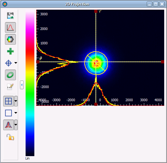
Click to Enlarge
Figure 5.2 The 2D Projection graph shows the image from the Beam Profiler indicating the power intensity distribution within the selected Region of Interest (ROI). Buttons along the side allow users to save the image, show or hide the x and y scales, mark the centroid or peak positions, and display an approximated Beam Ellipse superimposed on the image.
Calculation Results
Beam Stability
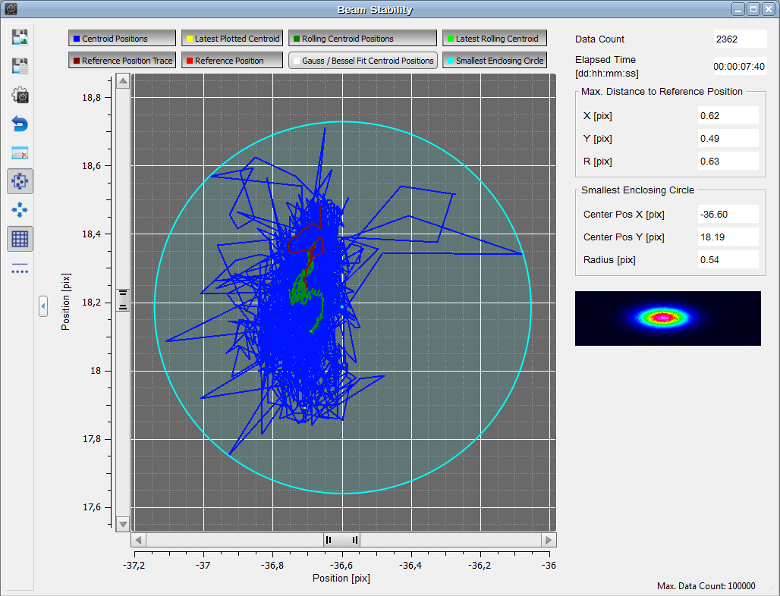
Click to Enlarge
Figure 5.4 The Beam Stability Window allows the stability versus time to be recorded and viewed. Display options include the Centroid Positions, Latest Plotted Centroid, Rolling Centroid Positions, Reference Positions, and Smallest Enclosing Circle.
Plot Centroid and Peak Positions
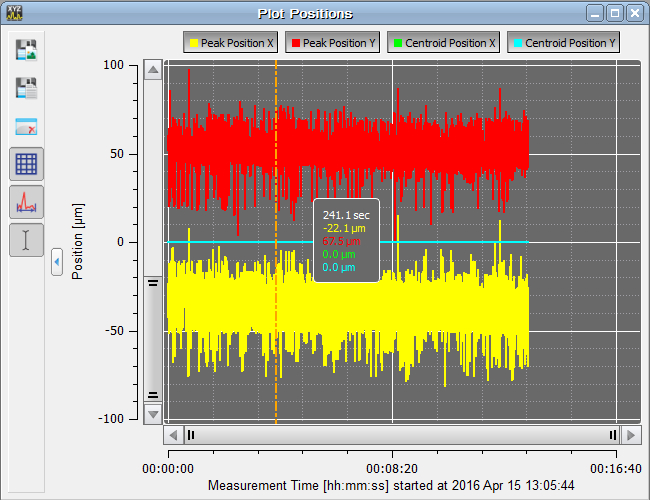
Click to Enlarge
Figure 5.5 The positions of the X and Y peak and X and Y centroid positions can be displayed as a function of time in this window.
M2 Measurements
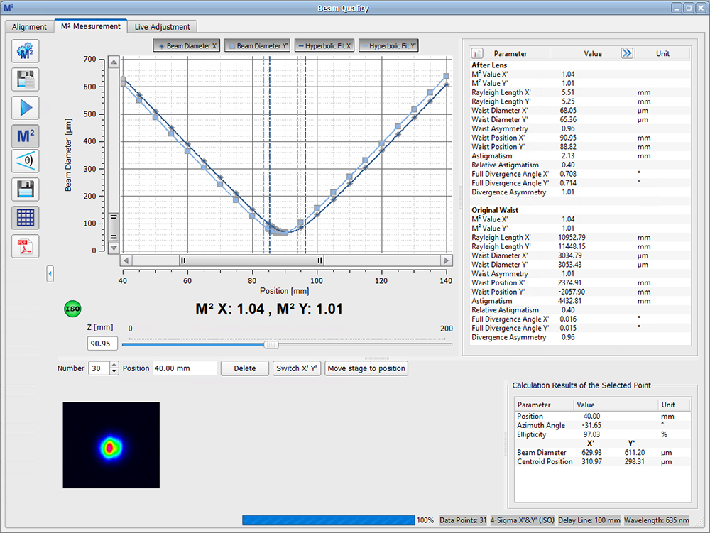
Click to Enlarge
Figure 5.6 The beam diameter and location of the beam waist are shown after an M² analysis has been performed. Note: This functionality is only enabled when using a beam profiler with one of the M² systems.
Divergence Measurements
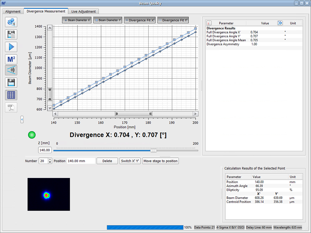
Click to Enlarge
Figure 5.7 The divergence of the beam is shown after an M² analysis has been performed. Note: This functionality is only enabled when using a beam profiler with one of the M² systems.
SOFTWARE
| System Requirements | ||
|---|---|---|
| Operating System | Windows® 8.1 (32 Bit or 64 Bit), 10 (32 Bit or 64 Bit), or 11 (for Beam Version 9.0 or Higher) |
|
| Connectivity | Scanning-Slit | USB 2.0 High Speed Port |
| Camera | USB 3.0 High Speed Port | |
| Monitor Resolution | 1024 x 758 Pixel (Min), ≥16 Bit Color Depth | |
| Processor (CPU) | Minimum | ≥3.0 GHz Intel Core (i5 or Higher)a |
| Recommended | Intel Core 2 i5 or AMD Ryzen 5 (3.0 GHz Min) | |
| Memory (RAM) | Minimum | 4.0 GB RAM |
| Recommended | 8.0 GB RAM | |
| Graphics Adapter | Required | OpenGL (Specification GLX 1.3 Up) |
| Minimum | Radeon: X100 Series ≥X850, X1000 Series ≥X1600, HD Series ≥2400; Geforce: 7 Series ≥7600, 8 Series ≥ 8500, 9 Series ≥9600; Quadro: FX Series ≥FX770M |
|
| Recommended | Radeon: HD Series ≥7000; Geforce: GTX Series ≥500; |
|
| Hard Drive | Minimum | 2 GB of Available Disk Space |
Software Packages for Thorlabs' Beam Profilers
The Beam software package can be downloaded by clicking on the Software button below. Please refer to the manual's programming references for interfacing with our beam profilers using LabVIEW™, C, Visual C#, and Python.
BC207 Series Profilers are compatible with Beam version 8.0 or higher. BC210C Series Profilers are compatible with Beam version 9.0 or higher.
Features
- Settings Panel Displays All Important Parameters in a Central Location
- Customizable Calculation Results
- Measured Parameters can be Individually Hidden
- Adjustable Row Heights
- Enhanced Beam Stability Window Measures and Displays the
Smallest Enclosing Circle Around the Centroid Point Cloud
- Alignment Wizard to Aid in Correctly Aligning the M2MS M2 Measurement Systems
- Language Settings of English, German, or Chinese
Software
Version 9.2.6002.614 (February 12, 2025)
Standard full version of software package for 32-bit and 64-bit Windows with driver and graphical user interface for operating the device in standard applications.
CMOS Camera Beam Profilers, Ø20 µm - 7.0 mm
- 5.0 MP CMOS Camera-Based Analysis of Complex Beam Profiles
- Each Profiler Includes Six ND Filters on a Wheel
- Combine with Extension Sets Below to Build Complete M2 Measurement Systems
- Physical Dimensions (Including Filter Wheel): 94.3 mm x 84.8 mm x 85.7 mm (3.71'' x 3.34'' x 3.37'')
The BC207UV(/M) and BC207VIS(/M) CMOS camera beam profilers are designed for beam analysis over the 245 - 400 nm or 350 - 1100 nm wavelength range, respectively. Each includes a front-mounted filter wheel with six ND filters (see the ND Filters tab more details) to attenuate the beam and a 5.0 MP CMOS camera to image the beam profile in two dimensions. Each profiler has two 1/4"-20 (M6 x 1.0 mm) taps on the bottom for post mounting; one of these holes, located closest to the measurement plane, can also be used to attach the beam profiler to an M2 extension set (available below).
A USB 3.0 A to micro B cable (3.0 m length), filter cap, and quick-start guide are shipped with each beam profiler.
Part Number | Description | Price | Availability |
|---|---|---|---|
BC207UV/M | CMOS Camera Beam Profiler, 245 - 400 nm, Ø20 µm - Ø7.0 mm, Metric | $5,755.64 | Lead Time |
BC207VIS/M | CMOS Camera Beam Profiler, 350 - 1100 nm, Ø20 µm - Ø7.0 mm, Metric | $5,403.25 | Today |
BC207UV | CMOS Camera Beam Profiler, 245 - 400 nm, Ø20 µm - Ø7.0 mm, Imperial | $5,755.64 | Lead Time |
BC207VIS | CMOS Camera Beam Profiler, 350 - 1100 nm, Ø20 µm - Ø7.0 mm, Imperial | $5,403.25 | Today |
Compact CMOS Camera Beam Profilers, Ø20 µm - Ø10.0 mm
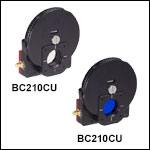
- 12.3 MP CMOS Camera-Based Analysis of Complex Beam Profiles
- Each Profiler Includes Six ND Filters on a Wheel
- Low-Profile Housing to Fit Into Space-Constrained Optical Setups
- Physical Dimensions (Including Filter Wheel): 95.8 mm x 88.4 mm x 34.7 mm (3.77'' x 3.48'' x 1.37'')
- Combine with Extension Sets Below to Build Complete M2 Measurement Systems
The BC210CU(/M) and BC210CV(/M) CMOS camera beam profilers have a compact housing designed for beam analysis over the 245 - 400 nm or 350 - 1100 nm wavelength range, respectively. Each profiler includes a front-mounted filter wheel with six ND filters (see the ND Filters tab for more details) to attenuate the beam, and a 12.3 MP CMOS camera to image the beam profile in two dimensions. Each profiler has two 1/4"-20 (M6 x 1.0 mm) taps on the bottom for post mounting or attachment to an M2MS series M2 measurement system (available separately below). There is an additional 1/4"-20 (M6 x 1.0 mm) tap on the bottom for post mounting only.
A USB 3.0 A to right-angle micro B cable (3.0 m length), filter cap, and quick-start guide are shipped with each beam profiler.
Part Number | Description | Price | Availability |
|---|---|---|---|
BC210CU/M | Compact CMOS Camera Beam Profiler, 245 - 400 nm, Ø20 µm - Ø10.0 mm, Metric | $7,967.22 | Today |
BC210CV/M | Compact CMOS Camera Beam Profiler, 350 - 1100 nm, Ø20 µm - Ø10.0 mm, Metric | $7,639.80 | Lead Time |
BC210CU | Compact CMOS Camera Beam Profiler, 245 - 400 nm, Ø20 µm - Ø10.0 mm, Imperial | $7,967.22 | Today |
BC210CV | Compact CMOS Camera Beam Profiler, 350 - 1100 nm, Ø20 µm - Ø10.0 mm, Imperial | $7,639.80 | Today |
M² Measurement Extension Sets
| Item # | M2MS-AL | M2MS | |
|---|---|---|---|
| Wavelength Range | 250 - 600 nma | 400 - 2700 nma | |
| Beam Profiler Compatibilityb | BC207UV(/M)b BP209-VIS(/M) BC210CU(/M)b |
BC207VIS(/M)c BP209-VIS(/M) BP209IR1(/M) BP209-IR2(/M) BC210CV(/M)c |
|
| Internal Translation Stage |
Travel Range | 100 mm | |
| Velocity (Max) | 500 mm/s | ||
| Effective Translation Range | 200 mm (Total) ±100 mm (from Focal Point) |
||
| Lens Focal Length | 250 mm | ||
| Optical Axis Height | 70 mm (Without Additional Feet) |
||
| M² Measurement Range | >1.0 (No Upper Limit) | ||
| Typical M² Accuracy | ±5% (Depends on Optics and Alignment) |
||
| Minimum Detectable Divergence Angle |
<0.1 mrad | ||
| Applicable Light Sources | CW, Pulseda | ||
| Typical Measurement Time | 15 - 30 s |
||
| General Specifications | |||
| Size | 300 mm x 175 mm x 109 mm (Without Beam Profiler) |
||
| Weight | 4.2 kg (Without Beam Profiler) |
||
- Combine with BC207 Series or BC210C Series CMOS Camera Beam Profilers to Build a Complete M2 Measurement System
- Mirrors for the 250 - 600 nm or 400 - 2700 nm Range
- Mounting Adapters for BC207 and BC210C* Series Camera Beam Profilers and BP209 Scanning Slit Beam Profilers
- Includes an Alignment Laser
These extension sets are designed to convert Thorlabs' Camera or Scanning Slit Beam Profilers into a fully automated, motorized M² measurement system. The
The beam profiler and focusing lens remain in a fixed position. For M2 measurements, the beam path length is varied using a movable retroreflector mounted on a translation stage, which has a translation range of 100 mm and a maximum velocity of 500 mm/s.
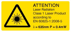 Figure G3.1 Each extension kit ships with a Class 1 alignment laser.
The side of the M² measurement system features an integrated USB 2.0 hub, which has ports for the slit beam profiler, one other device such as the TSP01 USB temperature and humidity controller, and a mini USB output connection to a PC. The translation stage inside of the system also communicates with the computer through this hub. As the BC207 and BC210C series beam profilers use USB 3.0 ports, they should be connected directly to a PC using their included USB 3.0 cables when used with the M2MS(-AL) system. The M2 measurement system extension set is controlled via the Thorlabs Beam software package which is also used to control our beam profilers (see the Software tab) and enables accurate measurements of a variety of beam-related parameters.
The housing of the M2 measurement extension set rests on four feet at the corners created by a 0.5 mm deep relief cut in the base. A set of RDF1 rubber damping feet are included. Five M6 x 1.0 mm taps allow for the installion of four damping feet with one near each corner or in a configuration using three damping feet.
More information about these complete M² measurement systems, as well information about M2 measurement systems that incorporate our scanning slit beam profilers can be found here.
*Users who purchased an M2 measurement system extension set before August 8, 2023 and wish to use a BC210C Series Camera Beam Profiler may receive the appropriate adapter by contacting Tech Sales.
Lenses Included with M2MS-AL*
Lenses with f = 250 mm Mounted in CXY1QF Quick Release Plate:
*Additional lenses for shorter UV wavelengths and the CXY1QF quick release front plate are available separately to enable further customization of the M2 measurement system.
Lenses Included with M2MS*
Lenses with f = 250 mm Mounted in CXY1QF Quick Release Plate:
- LA1461-A (AR Coated for 350 - 700 nm)
- LA1461-B (AR Coated for 650 - 1050 nm)
- LA1461-C (AR Coated for 1050 - 1700 nm)
- LA5255-D (AR Coated for 1650 - 3000 nm)
*Additional lenses for longer IR wavelengths and the CXY1QF quick release front plate are available separately to enable further customization of the M2 measurement system.
Accessories Included with M2MS-AL and M2MS
- Alignment Laser
- USB 2.0 to Mini B Cable, 3 m
- USB 2.0 to Mini B (Angled), 0.5 m)
- 15 V, 3.0 A Power Supply
- Adapters for BC207, BC210C, and BP209 Profilers
- 0.05" Hex Key
- 3 mm Balldriver
- Four CL6 Rail Clamps
- Six M4 x 0.7 mm Cap Screws
Part Number | Description | Price | Availability |
|---|---|---|---|
M2MS-AL | M² Measurement System Extension Set, 250 - 600 nm | $7,295.97 | Lead Time |
M2MS | M² Measurement System Extension Set, 400 - 2700 nm | $7,295.97 | Today |