Products Home / Controllers / Active Auto-Alignment Devices / Rack System NanoTrak® Active Auto-Alignment Module
Rack System NanoTrak® Active Auto-Alignment Module
- Advanced Active Alignment
- High-Voltage Piezo Output Channels for Precise Positioning
- IR (InGaAs) Detector Included
- Visible (Si) Detector Available Separately
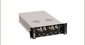
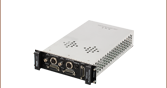
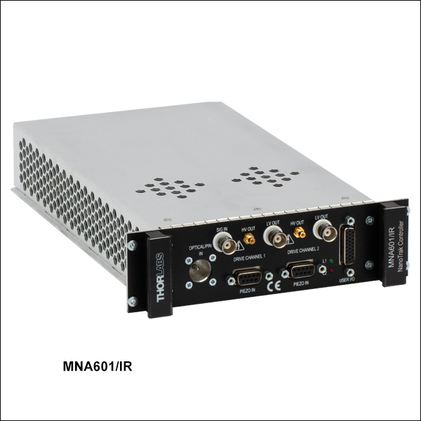
MNA601/IR
Rack Module
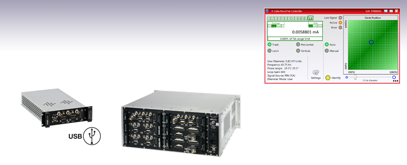
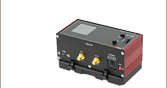
Application Idea
MNA601/IR Module in MMR601 Rack (Back View)
Full Suite of Software Support Tools Included


Please Wait
Applications
- Fiber-to-Fiber Active Alignment
- Fiber-to-Free-Space Active Alignment
- Optical Device Alignment
- Waveguide Characterization
- Fiber Characterization and Testing
- Fiber Pigtailing of Active and Passive Devices
- Maintain High Power Throughput to an Entire Optical Setup
| Rack System Motion Control Modules |
|---|
| 2-Channel Piezo Control Module |
| 2-Channel Stepper Motor Controller Module |
| 2-Channel NanoTrak® Auto-Alignment Module |
| 2-Channel Brushless DC Motor Controller Module |
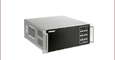
| USB Motion Control 19" Rack Chassis |
| All Thorlabs' Rack System Modules require the use of the MMR601 or MMR602 Rack System Enclosure. Independent operation of the modules outside the enclosure is not possible. |
Features
- Active Alignment System with Advanced Light Search Algorithm
- Tracking Feature Maintains Optimum Throughput Indefinitely
- Latch Mode to Maintain Alignment Stability over Time
- MNA601/IR Module Provides 2-Axis Control
- MMR601 and MMR602 Rack Systems Hold up to 6 Modules
- Two Piezo Actuator Output Channels Provide Closed-Loop Feedback
- IR (InGaAs) Detector & SMB Connector for External Diodes Included
- Visible (Si) Detector Available Separately
- Full Software GUI Control Suite and Support for Third-Party Custom Applications
The modular NanoTrak Auto-Alignment Controller is designed to maximize the power throughput of a fiber-to-fiber or fiber-to-free-space system. By driving a piezo-actuated stage to move the fiber tip in a circular scan pattern, the controller performs a power gradient search to determine the direction of peak power and positions the fiber for maximum throughput. Two high-voltage output channels provide the drive signal for the associated piezo actuators, eliminating the need for external piezo drivers. In combination with a multi-axis, piezo-driven stage, such as our 3-Axis NanoMax and 6-Axis NanoMax stages, a fiber alignment controller creates a complete auto-alignment system. It can be fully integrated into a rack system that is comprised of a selection of our plug-ins: brushless motor controllers, piezoelectric controllers, stepper motor controllers, and this NanoTrak autoalignment module.
USB connectivity provides easy 'Plug-and-Play' PC-controlled operation with the Kinesis® software package, which features new .NET controls that can be used by third-party developers working in the latest C, C#, LabVIEW™ or any .NET compatible languages to create custom applications. For more details, please see the Kinesis Software and Kinesis Tutorials tabs.
The initial coupling of light from one device (e.g. fiber) to another involves searching a multidimensional space until a signal is detected. The NanoTrak support software offers a series of motor search algorithms for this first light detection. Although used primarily for aligning optical fibers and integrated optical devices, the NanoTrak is ideal for automating just about any labor intensive alignment tasks such as waveguide characterization, fiber pigtailing of active and passive devices, as well as a multitude of other R&D applications.
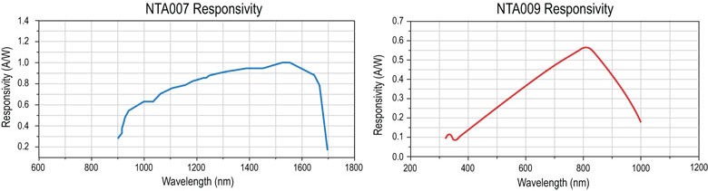
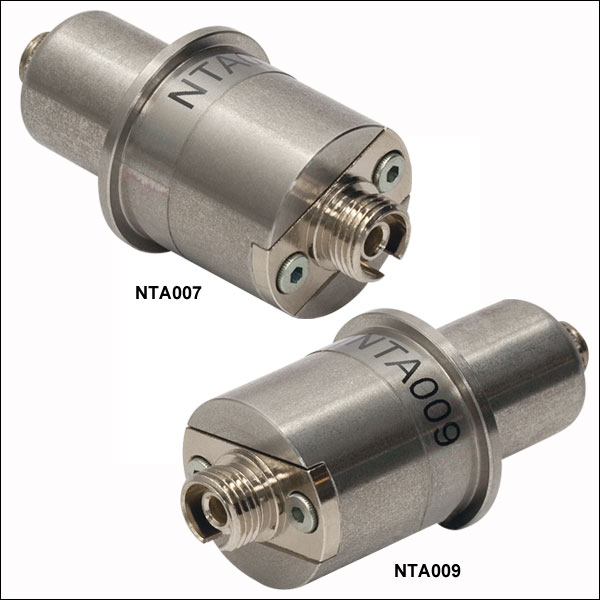
The NanoTrak module is supplied with an InGaAs detector (item # NTA007) for infrared (900 - 1700 nm) wavelengths and a PIN diode SMB input for use with external detector heads. A Si detector (item # NTA009) for visible (320 - 1100 nm) wavelengths is available separately as detailed in Table 1.1.
Cabling
Cables for connecting actuators or stages to the controller are shipped with the actuators or stages, not the controller. If you need help identifying the appropriate replacement cable, please contact Tech Support.
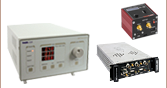
| Table 1.1 NanoTrak® Automated Fiber Alignment Controllers | ||
|---|---|---|
| K-Cube® 2-Channel Controllers | Benchtop 2-Channel Controller | Modular 2-Channel Rack System Module |
Module Specifications
| Signal Measurement | |
|---|---|
| PIN Photodiode | |
| Mechanical Connector | SMB Male |
| Photocurrent Range | 1 nA to 10 mA |
| Optical Connector | FC/PC |
| NanoTraking | |
| Circle Scanning Frequency | 1 to 300 Hz |
| Circle Position Range | <1% to >99% MPE |
| Circle Diameter Adj. Modes | Automatic and Manual |
| Signal Phase Compensation | ±180° |
| Piezoelectric Input/Output | |
| Number of Piezo Channels | 2 |
| HV Output Connectors | |
| Connector Type | SMC Male |
| Voltage Output | 0 to 75 VDC/Channel |
| Voltage Stability | 100 ppm over 24 Hours |
| Noise | <3 mV (RMS) |
| Output Current | 500 mA/Channel |
| Analog Output Monitors | |
| Connector Type | BNC |
| Voltage Range | 0 to 10 VDC |
| Strain Gauge Position Feedback | |
| Connector Type | 9-Pin D-Type Female |
| Feedback Type | AC |
| Other Input/Output | |
| Optical Power Monitor | |
| Connector Type | BNC |
| Voltage Range | 0 to 10 VDC |
| Ext Signal In Input | |
| Connector Type | BNC |
| Voltage Range | 0 to 10 VDC |
| User Control | |
| Connector Type | 26-Pin HD D-Type Female |
| Isolated Digital Inputs | 4 off TTL |
| Isolated Digital Outputs | 4 off TTL |
| Trigger Input | 1 off TTL |
| Trigger Output | 1 off TTL |
| Potentiometer Channel Ctrl Input | 1 - 10 kΩ (Each Channel) |
| Analog Channel Output Monitors | 0 to 10 VDC (Each Channel) |
| General | |
| Dimensions (W x D x H) | 190 mm x 270 mm x 50 mm |
| Weight | 1.5 kg (3.3 lbs) |
Optical Detector Specifications
| Item # | NTA009a | NTA007a |
|---|---|---|
| Detector Type | Si | InGaAs |
| Operating Wavelength | 320 - 1000 nm | 900 - 1700 nm |
| Active Area | Ø0.8 mm | Ø0.12 mm |
| Fiber Input | FC/PC | |
| Rise Time | 100 ps @ 12 V | |
| NEP | 1.5 x 10⁻¹⁵ W/√Hz | 4.5 x 10⁻¹⁵ W/√Hz |
| Dark Current | 0.01 nA @ 10 V | 0.05 nA @ 5 V |
NanoTrak® Controller
D-type Female
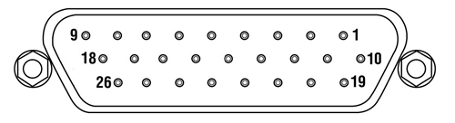
| Pin | Description | Return | Pin | Description | Return | Pin | Description | Return |
|---|---|---|---|---|---|---|---|---|
| 1 | DIG I/P 1a | 19 | 10 | DIG O/P 1a | 19 | 19 | Isolated Groundb | - |
| 2 | DIG I/P 2a | 19 | 11 | DIG O/P 2a | 19 | 20 | Ext Trigger I/P | 22 |
| 3 | DIG I/P 3a | 19 | 12 | DIG O/P 3a | 19 | 21 | Ext Trigger O/P | 22 |
| 4 | DIG I/P 4a | 19 | 13 | DIG O/P 4a | 19 | 22 | Ground | - |
| 5 | Channel 1 RS485 (+) | - | 14 | Channel 2 RS485 (+) | - | 23 | 5 V User O/P (Isolated) | - |
| 6 | Channel 1 RS485 (-) | - | 15 | Channel 2 RS485 (+) | - | 24 | Not Used | - |
| 7 | Not Used | - | 16 | Not Used | - | 25 | Analog Ground | - |
| 8 | Channel 2 10 V O/Pc | 25 | 17 | External Analog I/P CH2 0 - 10 V | 25 | 26 | Signal Power Outd | 25 |
| 9 | Channel 1 10 V O/Pc | 25 | 18 | External Analog I/P CH1 0 - 10 V | 25 |
Piezo Controller
D-type Female
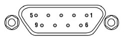
| Pin | Description | Return | Pin | Description | Return | Pin | Description | Return |
|---|---|---|---|---|---|---|---|---|
| 1 | Wheatstone Bridge Excitation | 4 or 6 | 4 | D.C.(+) or Equipment Grounda | - | 7 | D.C.(-) or Actuator ID Signala,b | 4 or 6 |
| 2 | +15Vc | 4 or 6 | 5 | Feedback Signal In | 4 or 6 | 8 | RS485 (-) | 9 |
| 3 | -15Vc | 4 or 6 | 6 | Equiptment Ground | - | 9 | RS485 (+) | 8 |
LV Out
BNC Female
0 to +10V. This output is mirrors HV OUT, 10V being equivalent to 75V on the HV outputs, and can be connected to an oscilloscope to enable the drive signal of the piezo actuator to be monitored.
HV Out
SMC

0 to 75V, 0 to 500mA. Provides the drive signal to the piezo actuator.
Signal In
BNC Female
0 to 10V, 100kΩ load. Used to receive a signal of optical power from an external power meter.
Software
Kinesis Version 1.14.57
The Kinesis Software Package, which includes a GUI for control of Thorlabs' Kinesis system controllers.
Also Available:
- Firmware Update Utilities
- Communications Protocol
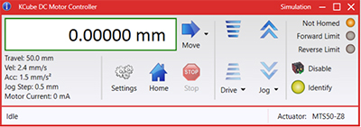
Figure 58A Kinesis GUI Screen
Thorlabs offers the Kinesis software package to drive our wide range of motion controllers. The software can be used to control devices in the Kinesis family, which covers a wide variety of motion controllers ranging from small, low-powered, single-channel drivers (such as the K-Cubes®) to high-power, multi-channel benchtop units and modular 19" rack nanopositioning systems (the MMR60x Rack System).
The Kinesis Software features .NET controls which can be used by 3rd party developers working in the latest C#, Visual Basic, LabVIEW™, or any .NET compatible languages to create custom applications. Low-level DLL libraries are included for applications not expected to use the .NET framework and APIs are included with each install. A Central Sequence Manager supports integration and synchronization of all Thorlabs motion control hardware.
By providing this common software platform, Thorlabs has ensured that users can mix and match any of our motion control devices in a single application, while only having to learn a single set of software tools. In this way, it is perfectly feasible to combine any of the controllers from single-axis to multi-axis systems and control all from a single, PC-based unified software interface.
The software package allows two methods of usage: graphical user interface (GUI) utilities for direct interaction with and control of the controllers 'out of the box', and a set of programming interfaces that allow custom-integrated positioning and alignment solutions to be easily programmed in the development language of choice.
Thorlabs' Kinesis software features new .NET controls which can be used by third-party developers working in the latest C#, Visual Basic, LabVIEW™, or any .NET compatible languages to create custom applications.
C#
This programming language is designed to allow multiple programming paradigms, or languages, to be used, thus allowing for complex problems to be solved in an easy or efficient manner. It encompasses typing, imperative, declarative, functional, generic, object-oriented, and component-oriented programming. By providing functionality with this common software platform, Thorlabs has ensured that users can easily mix and match any of the Kinesis controllers in a single application, while only having to learn a single set of software tools. In this way, it is perfectly feasible to combine any of the controllers from the low-powered, single-axis to the high-powered, multi-axis systems and control all from a single, PC-based unified software interface.
The Kinesis System Software allows two methods of usage: graphical user interface (GUI) utilities for direct interaction and control of the controllers 'out of the box', and a set of programming interfaces that allow custom-integrated positioning and alignment solutions to be easily programmed in the development language of choice.
For a collection of example projects that can be compiled and run to demonstrate the different ways in which developers can build on the Kinesis motion control libraries, click on the links below. Please note that a separate integrated development environment (IDE) (e.g., Microsoft Visual Studio) will be required to execute the Quick Start examples. The C# example projects can be executed using the included .NET controls in the Kinesis software package (see the Kinesis Software tab for details).
 |
Click Here for the Kinesis with C# Quick Start Guide Click Here for C# Example Projects Click Here for Quick Start Device Control Examples |
|
LabVIEW
LabVIEW can be used to communicate with any Kinesis-based controller via .NET controls. In LabVIEW, you build a user interface, known as a front panel, with a set of tools and objects and then add code using graphical representations of functions to control the front panel objects. The LabVIEW tutorial, provided below, provides some information on using the .NET controls to create control GUIs for Kinesis-driven devices within LabVIEW. It includes an overview with basic information about using controllers in LabVIEW and explains the setup procedure that needs to be completed before using a LabVIEW GUI to operate a device.
 |
Click Here to View the LabVIEW Guide Click Here to View the Kinesis with LabVIEW Overview Page |
|
| Posted Comments: | |
Rich Rademacher
(posted 2019-10-09 11:46:45.533) Hello,
I am working on a nanopositioning project using the MMR601 product. This project requires custom automation and so we cannot use the APT or Kinesis GUI. I do see you have the APT protocol documented and I think we can use this. However, USB is a problem for us.
I see the MMR601 has an external RS485 port on the D-sub user connector. Does this port use the same APT protocol, but obviously without the FTDI chip USB wrapper?
Thanks,
Rich cwright
(posted 2019-10-11 06:19:55.0) Hello Rich,
thank you for contacting us. Yes, the serial commands described in the communication protocol can be used to communicate with the controller over the RS484 pins. The communications protocol is identical regardless of the interface used - USB or RS485. TechnicalMarketing
(posted 2007-10-19 14:58:03.0) Thank you for taking the time to point out the typo in our price box. We appreatiate your contribution to our effort of improving the accuracy and content of Thorlabs website. cjohns
(posted 2007-10-19 14:20:35.0) MNA601/IR - Should be "InGaAs" detector? |

 Zoom
ZoomWhen used with the MMR601 or MMR602 rack systems, the NanoTrak® controller optimizes the coupling power when aligning optical devices. The output piezo drive signal is used to position the input and output devices for optimum throughput. It is shipped with an IR range (InGaAs) detector and a PIN current adapter. A visible range (Si) detector (NTA009) is available separately (see below).

 Zoom
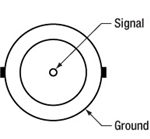
Zoom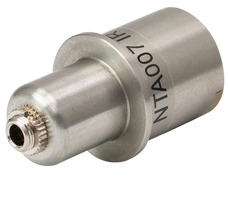 Click to Enlarge
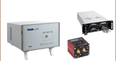
Figure 393A Detector Head, Back View
These infrared (NTA007) and visible (NTA009) wavelength detector heads are compatible with the benchtop (BNT001/IR), previous-generation T-Cube™ (TNA001/IR), and rack-mounted (MNA601/IR) NanoTrak® controllers. Both detector heads have an FC/PC optical fiber input and interface with the benchtop controller via a jack at the back of the detector, as shown Figure 393A.
| Item # | Wavelength Range | Active Area | Fiber Input | Dark Current | Junction Capacitance |
|---|---|---|---|---|---|
| NTA009 | 320 - 1000 nm | Ø 0.8 mm | FC/PC | 0.01 nA (Typ.) @ 10 V | 3.00 pF(Typ.) @ 10 V |
| NTA007 | 900 - 1700 nm | Ø 0.12 mm | FC/PC | 0.05 nA (Typ.) @ 5 V | 2.0 pF (Typ.) @ 5 V |