 Products Home / Optomechanical Components / Optomechanical Mounts / Component Mounts / V-Mounts / Optical Fiber Clamps, Post-Mountable and SM1-Threaded
Optical Fiber Clamps, Post-Mountable and SM1-Threaded

- Adjustable Force Magnetic Clamp for Fibers with Ø250 µm Coatings
- Clamping Arm Swings Clear for Easy Loading
- Rubber Pad Provides Excellent Holding Force
Ø1" Lens Tube
SM1 External
Threads
SM1F1-250
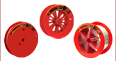
Soft Rubber Pad Securely Clamps Ø250 µm Fiber in Machined V-Groove
Magnetically Coupled Swing Arm Simplifies Loading/Unloading Fiber
8-32 (M4) Tap
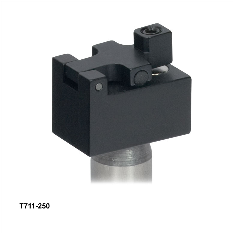
T711-250


Please Wait
| Other Bare Fiber Mounts | ||||
|---|---|---|---|---|
| Post Mountable or SM Threaded |
Post Mountable with Vacuum Port |
Flexure Stage Compatible | ||
| V-Mounts | Fiber Block | Clamps | Chucks | Rotators |
Features
- Adjustable Force Magnetic Clamps for Fibers with Ø250 µm Coatings
- T711-250: Post Mountable via 8-32 (M4) Tapped Hole for Optical Table Applications
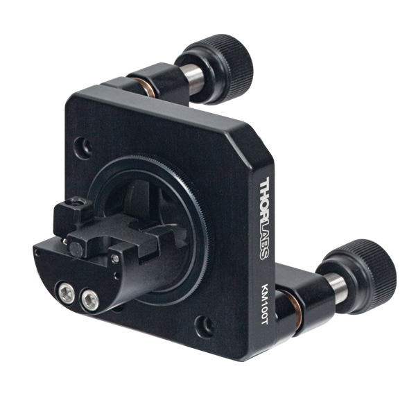
- SM1F1-250: Externally Threaded for use with SM1-Threaded Products
- Clamping Arm Swings Clear for Easy Loading and Unloading of the Optical Fiber
- Rubber Padding Provides Excellent Holding Force without Damaging the Optical Fiber
These general purpose fiber clamps provide easy means for incorporating glass or plastic optical fibers into optomechanical post assemblies or SM1-threaded components. The precision V-groove and rubber pad are designed to clamp onto the buffer of single mode or multimode fibers without damaging them. The combination of a magnet in the main mounting body and magnetic steel setscrew in the clamping arm provide a means to dynamically adjust the clamping force. Move the magnetic setscrew closer to the main body to increase the clamping force. Conversely, adjusting the setscrew away from the magnet decreases the clamping force.
This product is often used along with one of our popular Aspheric Lenses to create a fiber output collimator that provides near-diffraction-limited performance. We also offer a fiber holding block with vacuum port and integrated FiberPort Collimators/Couplers for FiberBench systems. For our Fiber Launch stage systems, we offer bare fiber mounts, chucks, and rotators. Please see our complete collection of Fiber Optomechanics.

Insights into Optical Fiber
Scroll down to read about:
- When does NA provide a good estimate of the fiber's acceptance angle?
- Why is MFD an important coupling parameter for single mode fibers?
- Does NA provide a good estimate of beam divergence from a single mode fiber?
Click here for more insights into lab practices and equipment.
When does NA provide a good estimate of the fiber's acceptance angle?
Click to Enlarge
Figure 192A Rays incident at angles ≤θmax will be captured by the cores of multimode fiber, since these rays experience total internal reflection at the interface between core and cladding.
Click to Enlarge
Figure 192B The behavior of the ray at the boundary between the core and cladding, which depends on their refractive indices, determines whether the ray incident on the end face is coupled into the core. The equation for NA can be found using geometry and the two equations noted at the top of this figure.
Numerical aperture (NA) provides a good estimate of the maximum acceptance angle for most multimode fibers, as shown in Figure 192A. This relationship should not be used for single mode fibers.
NA and Acceptance Angle
Incident light is modeled as rays to obtain the relationship between NA and the maximum acceptance angle (θmax ), which describes the fiber's ability to gather light from off-axis sources. The equation at the top of Figure 192A can be used to determine whether rays traced from different light sources will be coupled into the fiber's core.
Rays with an angle of incidence ≤θmax are totally internally reflected (TIR) at the boundary between the fiber's core and cladding. As these rays propagate down the fiber, they remain trapped in the core.
Rays with angles of incidence larger than θmax refract at the interface between core and cladding, and this light is eventually lost from the fiber.
Geometry Defines the Relationship
The relationship among NA, θmax , and the refractive indices of the core and cladding, ncore and nclad , respectively, can be found using the geometry diagrammed in Figure 192B. This geometry illustrates the most extreme conditions under which TIR will occur at the boundary between the core and cladding.
The equations at the top of Figure 192B are expressions of Snell's law and describe the rays' behavior at both interfaces. Note that the simplification sin(90°) = 1 has been used. Only the indices of the core and cladding limit the value of θmax .
Angles of Incidence and Fiber Modes
When the angle of incidence is ≤θmax , the incident light ray is coupled into one of the multimode fiber's guided modes. Generally speaking, the lower the angle of incidence, the lower the order of the excited fiber mode. Lower-order modes concentrate most of their intensity near the center of the core. The lowest order mode is excited by rays incident normally on the end face.
Single Mode Fibers are Different
In the case of single mode fibers, the ray model in Figure 192B is not useful, and the calculated NA (acceptance angle) does not equal the maximum angle of incidence or describe the fiber's light gathering ability.
Single mode fibers have only one guided mode, the lowest order mode, which is excited by rays with 0° angles of incidence. However, calculating the NA results in a nonzero value. The ray model also does not accurately predict the divergence angles of the light beams successfully coupled into and emitted from single mode fibers. The beam divergence occurs due to diffraction effects, which are not taken into account by the ray model but can be described using the wave optics model. The Gaussian beam propagation model can be used to calculate beam divergence with high accuracy.
Date of Last Edit: Jan. 20, 2020
Why is MFD an important coupling parameter for single mode fibers?
Click to Enlarge
Figure 192C For maximum coupling efficiency into single mode fibers, the light should be an on-axis Gaussian beam with its waist located at the fiber's end face, and the waist diameter should equal the MFD. The beam output by the fiber also resembles a Gaussian with these characteristics. In the case of single mode fibers, the ray optics model and NA are inadequate for determining coupling conditions. The mode intensity (I ) profile across the radius ( ρ ) is illustrated.
As light propagates down a single mode fiber, the beam maintains a cross sectional profile that is nearly Gaussian in shape. The mode field diameter (MFD) describes the width of this intensity profile. The better an incident beam matches this intensity profile, the larger the fraction of light coupled into the fiber. An incident Gaussian beam with a beam waist equal to the MFD can achieve particularly high coupling efficiency.
Using the MFD as the beam waist in the Gaussian beam propagation model can provide highly accurate incident beam parameters, as well as the output beam's divergence.
Determining Coupling Requirements
A benefit of optical fibers is that light carried by the fibers' guided mode(s) does not spread out radially and is minimally attenuated as it propagates. Coupling light into one of a fiber's guided modes requires matching the characteristics of the incident light to those of the mode. Light that is not coupled into a guided mode radiates out of the fiber and is lost. This light is said to leak out of the fiber.
Single mode fibers have one guided mode, and wave optics analysis reveals the mode to be described by a Bessel function. The amplitude profiles of Gaussian and Bessel functions closely resemble one another, which is convenient since using a Gaussian function as a substitute simplifies the modeling the fiber's mode while providing accurate results (Kowalevicz).
Figure 192C illustrates the single mode fiber's mode intensity cross section, which the incident light must match in order to couple into the guided mode. The intensity (I ) profile is a near-Gaussian function of radial distance ( ρ ). The MFD, which is constant along the fiber's length, is the width measured at an intensity equal to the product of e-2 and the peak intensity. The MFD encloses ~86% of the beam's power.
Since lasers emitting only the lowest-order transverse mode provide Gaussian beams, this laser light can be efficiently coupled into single mode fibers.
Coupling Light into the Single Mode Fiber
To efficiently couple light into the core of a single-mode fiber, the waist of the incident Gaussian beam should be located at the fiber's end face. The intensity profile of the beam's waist should overlap and match the characteristics of the mode intensity cross section. The required incident beam parameters can be calculated using the fiber's MFD with the Gaussian beam propagation model.
The coupling efficiency will be reduced if the beam waist is a different diameter than the MFD, the cross-sectional profile of the beam is distorted or shifted with respect to the modal spot at the end face, and / or if the light is not directed along the fiber's axis.
References
Kowalevicz A and Bucholtz F, "Beam Divergence from an SMF-28 Optical Fiber (NRL/MR/5650--06-8996)." Naval Research Laboratory, 2006.
Date of Last Edit: Feb. 28, 2020
Why is MFD an important coupling parameter for single mode fibers?
Significant error can result when the numerical aperture (NA) is used to estimate the cone of light emitted from, or that can be coupled into, a single mode fiber. A better estimate is obtained using the Gaussian beam propagation model to calculate the divergence angle. This model allows the divergence angle to be calculated for whatever beam spot size best suits the application.
Since the mode field diameter (MFD) specified for single mode optical fibers encloses ~86% of the beam power, this definition of spot size is often appropriate when collimating light from and focusing light into a single mode fiber. In this case, to a first approximation and when measured in the far field,
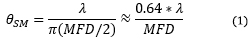 , , |
is the divergence or acceptance angle (θSM ), in radians. This is half the full angular extent of the beam, it is wavelength  )
)
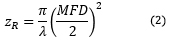
| Rayleigh Range: | ||
 |
||
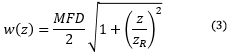
| Beam Radius at Distance z: | ||
 |
||
|
Figure 194D These curves illustrate the consequence of using NA to calculate the divergence (θSM ) of light output from a single mode fiber. Significant error in beam spot diameter can be avoided by using the Gaussian beam propagation model. This plot models a beam from SM980-5.8-125. The values used for NA and MFD were 0.13 and 6.4 µm, respectively. The operating wavelength was 980 nm, and the Rayleigh range was 32.8 µm. |
||
Gaussian Beam Approach
Although a diverging cone of light is emitted from the end face of a single mode optical fiber, this light does not behave as multiple rays travelling at different angles to the fiber's axis.
Instead, this light resembles and can be modeled as a single Gaussian beam. The emitted light propagates similarly to a Gaussian beam since the guided fiber mode that carried the light has near-Gaussian characteristics.
The divergence angle of a Gaussian beam can differ substantially from the angle calculated by assuming the light behaves as rays. Using the ray model, the divergence angle would equal sin-1(NA). However, the relationship between NA and divergence angle is only valid for highly multimode fibers.
Figure 194D illustrates that using the NA to estimate the divergence angle can result in significant error. In this case, the divergence angle was needed for a point on the circle enclosing 86% of the beam's optical power. The intensity of a point on this circle is a factor of 1/e2 lower than the peak intensity.
Equations (2) and (3) were used to accurately model the divergence of the beam emitted from the single mode fiber's end face. The values used to complete the calculations, including the fiber's MFD, NA, and operating wavelength are given in Figure 194D's caption. This rate of beam divergence assumes a beam size defined by the 1/e2 radius, is nonlinear for distances z < zR, and is approximately linear in the far field (z >> zR).
The angles noted on the plot were calculated from each curve's respective slope. When the far field approximation given by Equation (1) is used, the calculated divergence angle is 0.098 radians (5.61°).
References
Kowalevicz A and Bucholtz F, "Beam Divergence from an SMF-28 Optical Fiber (NRL/MR/5650--06-8996)." Naval Research Laboratory, 2006.
Date of Last Edit: Feb. 28, 2020
Content improved by our readers!
| Posted Comments: | |
Anthony Mastromarino
(posted 2025-03-21 05:58:33.423) A fiber clamp for jacketed fiber would be nice to have as a post-mounted or cage mounted strain relief. Something for clamping to 900 um and 3mm fiber cables, SM1F1-900 and SM1F1-3. All you should need to do is increase the depth of the v-groove. You might need to verify that the rubber will provide enough friction on contact with jacket vs. bare fiber in current design. jdelia
(posted 2025-03-21 01:28:13.0) Thank you for contacting Thorlabs and for providing this valuable feedback. While we do not currently offer such an item, I can certainly pass this request along to our design engineers via our internal suggestion forum for consideration as a future stock product. m.crank
(posted 2018-11-08 17:30:01.907) I have been trying to use a T711-250 for holding bare fibers. I've found that because the clamp covers the entire length of the holder, it makes it hard to hold the fiber in position while lowering the swing arm. It would be better if there was a section that isn't covered, that way the fiber can be pressed down with a finger while the swing arm is lowered. YLohia
(posted 2018-11-10 10:02:52.0) Hello, thank you for your feedback and please accept my apologies for the issues caused by this. I have also posted this on our internal engineering forum for further consideration. leidner
(posted 2018-05-17 14:51:15.333) We purchased a number of these, however they are very difficult to place fibers into because there is either a) no large scale knotch to lay fiber in such as in the newport 561-fh or 2) a place to hold the fiber down with ones finger that doesn't obstruct the magnetic closure such as what comes with fusion splicer v grooves. Either of these features would make you product an order of magnitude more usable than it is. As it stands we are happily paying ~4x the prices to get a more useful product in the 561-fh because of the difficulty in laying fiber into your v-groove. mmcclure
(posted 2018-05-17 03:28:49.0) This is a response from Matt at Thorlabs: Thank you very much for providing helpful feedback and suggestions to improve these products. I have relayed this information to our internal engineering forum, where we will consider them further. |

 Zoom
Zoom
| Accepted Diametersa | |
|---|---|
| Dmin | Dmax |
| 150 µm | 341 µm |
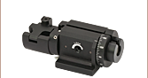
- Precision V-Groove Designed to Hold Ø150 µm to Ø341 µm Fibers
- Post-Mountable via 8-32 (M4) Tapped Hole
- Clamps with Adjustable Magnetic Force
The T711/M-250 post-mountable fiber clamp features a precision V-groove and rubber pad designed to clamp onto the buffer of single mode or multimode fibers without damaging them. With an 8-32 (M4) tap, this fiber clamp is compatible with Thorlabs' family of Ø1/2" Posts and can be integrated into optomechanical breadboards or optical table assemblies.

 Zoom
Zoom
Click to Enlarge
Figure G2.2 SM1F1-250 Mounting a Bare Fiber to a Power Sensor
Click to Enlarge
Figure G2.1 SM1F1-250 Attached to a Kinematic Mount via SM1 Threading
| Accepted Diametersa | |
|---|---|
| Dmin | Dmax |
| 150 µm | 341 µm |
- Precision V-Groove Designed to Hold Ø150 µm to Ø341 µm Fibers
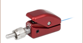
- Externally SM1-Threaded for use with SM1-Threaded Products
- Included SM1NT Locking Ring Allows Mount to be Locked in Lens Tube
The SM1F1-250 fiber clamp consists of a two-part assembly that allows the centration of the fiber to be changed independently from a lens tube. The V-groove and rubber pad design provide excellent holding force without damaging the fiber. With external SM1 threads and a locking ring, this fiber clamp is compatible with our SM1-threaded products, including threaded kinematic mounts (as shown in Figure G2.1) and Ø1" lens tubes. Alternatively,this mount can be used to secure a bare fiber end so that the output is incident on a power sensor, as seen in Figure G2.2. The outer profile of this clamp will fit through the clear aperture of a Ø1" lens tube, allowing a second lens tube to be screwed on for light-tight applications.