 Products Home
CMOS Camera Beam Profilers
- 245 - 400 nm or 350 - 1100 nm Wavelength Range
- Beam Diameter: 20 µm to 7.0 mm or 10.0 mm
- For Continuous Wave, Pulsed Beams, and Single Pulses
- M2 Measurement with Optional Extension Set
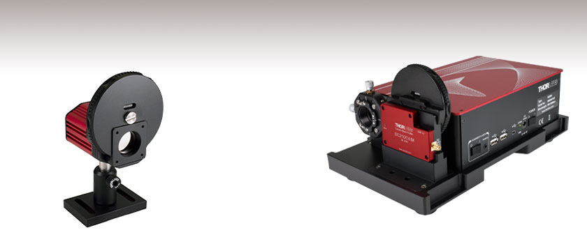
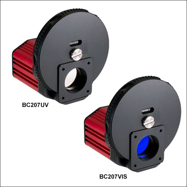
BC207UV
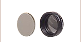
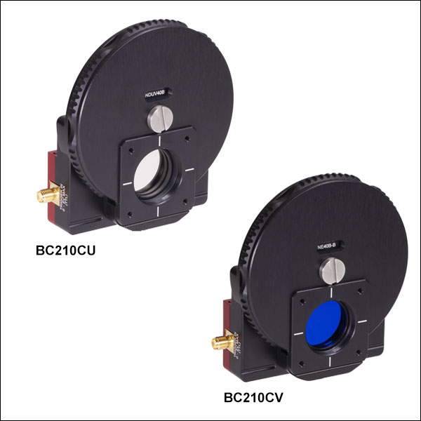
Filter Wheel with 6 Neutral Density Filters Included
(Post and Post Holder Sold Separately)
Application Idea
Use the BC210CV/M with the
M2MS M2 Extension Set to create a
complete beam quality measurement system.


Please Wait
| Item # | BC207UV(/M) | BC207VIS(/M) | BC210CU(/M) | BC210CV(/M) |
|---|---|---|---|---|
| Wavelength Range | 245 - 400 nma | 350 - 1100 nm | 245 - 400 nma | 350 - 1100 nm |
| Power Range | 20 fW - 1 Wb | 40 fW - 1 Wc | 20 fW - 1 Wb | 40 fW - 1 Wc |
| Beam Diameter | 20 µm - 7.0 mm | 20 µm - 10.0 mm | ||
| Compatible Light Sources | CW, Pulsedd | |||
| Sensor Size | 8.45 mm x 7.07 mm | 14.13 mm x 10.32 mm | ||
| Resolution | 5.0 MP | 12.3 MP | ||
Features
- Full 2D Analysis of Continuous Wave or Pulsed Laser Beam Profiles
- High Resolution:
- 2448 x 2048 Pixels (BC207 Series)
- 4096 x 2992 Pixels (BC210C Series)
- Low Noise: Signal-to-Noise Ratio ≤ 71 dB
- 12-Bit CMOS Camera
- Large Sensor Area for Uniformity and Linearity (See Sensor Size in Table to the Right)
- Window Protects Sensor from Dust
- Integrated Filter Wheel with Six Neutral Density Filters
- User-Calibratable Power Readout
- Exposure Time: 27 µs to 1 s (BC207 Series) or 25 µs to 500 ms (BC210C Series)
- Gain Control from 0 to 12 dB
- Black Level and Ambient Light Compensation
- External Trigger Input
- Optional M² Extension Kit for Automated M² Analysis (See Below)
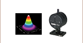
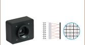
Thorlabs' Camera-Based Beam Profilers allow complex mode patterns (like flat top and donut) to be identified while optimizing a laser system. Compared to scanning slit beam profilers, camera beam profilers can capture a more detailed beam profile and provide a true 2D analysis of the beam's power density distribution.
Click to Enlarge
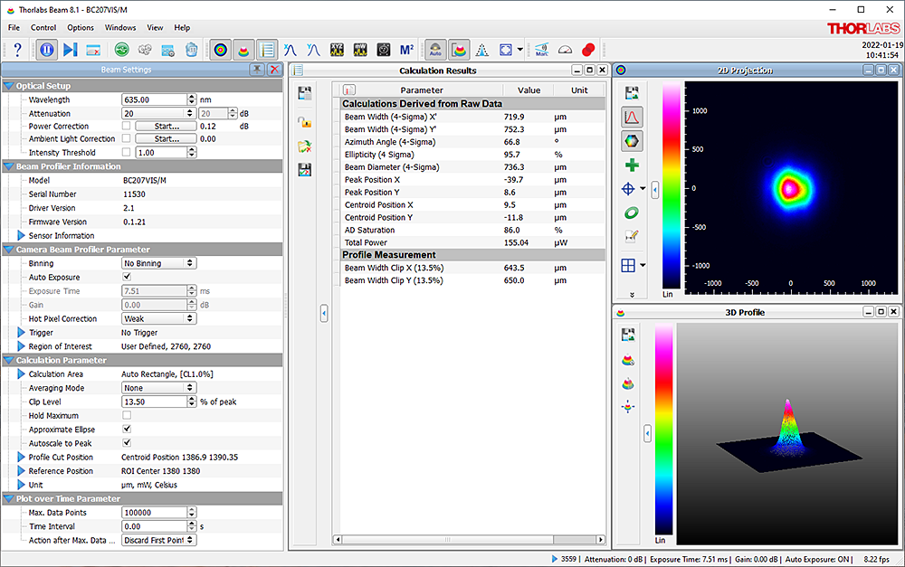
One Possible Configuration of the Beam Software GUI Showing Beam Settings, Calculation Results, 2D Projection, and 3D Profile.
These beam profilers are suited for use with either continuous wave or pulsed sources. Several trigger modes allow flexible capturing of single pulses, including a TTL input for triggered single pulse detection of signals with repetition rates up to 37 kHz; see the manual for more information.
The automatic dark level calibration provides very stable dark currents independent of the device settings, eliminating the need to recalibrate the dark level for each user setting.
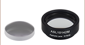
An integrated filter wheel with 6 high-quality neutral density (ND) filters allows the profiler to be adapted for use with beam intensities from nanowatts to 1 W (see the Specs and ND Filter tabs for details). Engraved labels are included on the filter wheel to indicate the ND filter pre-installed in each slot. If filters need to be removed or replaced, the wheel can be opened using a flathead screwdriver (see the manual for more information on removing filters).
Each filter housing is internally SM1 (1.035"-40) threaded for easy integration with Thorlabs' lens tube systems and mounts for other optical components such as additional attenuation filters. Both BC207 and BC210C Series Beam Profilers have 1/4"-20 (M6 x 1.0 mm) tapped holes for post mounting and attachment to an M2MS series M2 measurement system.
The integrated power meter can be user calibrated and is perfectly suited for simultaneous power and beam shape optimization without the need for an external power meter. A measured mean value of the ambient light intensity is subtracted from the beam profile measurement so as to compensate for ambient light. The automatic exposure and gain control feature adapts the camera settings to the actual beam intensity. The USB 3.0 interface allows up to 4 or 1.5 full frames per second at full resolution for the BC207 series or BC210C series, respectively. Measurements at higher frame rates can be achieved and transferred with reduced frame sizes.
The BC207 series and BC210C series camera beam profilers utilize Thorlabs' Beam software package, which can be downloaded via the links on the Software tab. Features of the software package are listed under the User Interface tab. Driver information, file locations, and reference notes for interfacing with our beam profilers using LabVIEW™, C, Visual C#, and Python are available in the user manual, which can be found by clicking on the red Docs icon (![]() ) next to the item number below. The BC207 series is compatible with software version 8.0 or higher while the BC210C series is compatible with software version 9.0 or higher.
) next to the item number below. The BC207 series is compatible with software version 8.0 or higher while the BC210C series is compatible with software version 9.0 or higher.
Extension sets are available below to convert these camera beam profilers into a fully-automated M² measurement system. Thorlabs also offers a scanning slit beam profiler, as well as complete M² analysis systems with included beam profilers.
| Item # | BC207UV(/M) | BC210CU(/M) | BC207VIS(/M) | BC210CV(/M) |
|---|---|---|---|---|
| Wavelength Range | 245 - 400 nma | 350 - 1100 nm | ||
| Power Range | 20 fW - 1 Wb,c | 40 fW - 1 Wc,d | ||
| Beam Diameter | 20 µm - 7.0 mm | 20 µm - 10.0 mm | 20 µm - 7.0 mm | 20 µm - 10.0 mm |
| Compatible Light Sources | CW, Pulsede | |||
| Protective Glass | WG41010-UV | NG3 Absorptive ND Filter, Ø25 mm, 1 mm Thick, Nominal Optical Density: 1.0 |
||
| Absorptive Neutral Density Filters | ||||
| Nominal Values | 20 dB, 30 dB, 40 dBf | 20 dB, 40 dB, 60 dB (Two Sets)g | ||
| AR Coating Wavelength Range | N/A | 350 - 700 nm (Three Filters) | ||
| 650 - 1050 nm (Three Filters) | ||||
| Reflective Neutral Density Filters | ||||
| Nominal Attenuation Values | 20 dB, 30 dB, 40 dB | N/A | ||
| Sensor | ||||
| Chip | 5.0 MP Sony IMX264LLR, 11.1 mm Diagonal, Windowless |
12.3 MP Sony IMX304LLR, 17.5 mm Diagonal, Windowless |
5.0 MP Sony IMX264LLR, 11.1 mm Diagonal, Windowless |
12.3 MP Sony IMX304LLR, 17.5 mm Diagonal, Windowless |
| Aperture Size (Max) | 8.45 mm x 7.07 mm | 14.13 mm x 10.32 mm | 8.45 mm x 7.07 mm | 14.13 mm x 10.32 mm |
| Pixel Size | 3.45 µm x 3.45 µm | |||
| Resolution (Max) | 2448 x 2048 pixel, ROI Selectable | 4096 x 2992 pixel, ROI Selectable | 2448 x 2048 pixel, ROI Selectable | 4096 x 2992 pixel, ROI Selectable |
| Camera | ||||
| Shutter | Global | |||
| Binning | 1 x 1; 2 x 2; 4 x 4; 8 x 8; 16 x 16 | |||
| Frame Rate (Max) @ Full Resolution | 4 fpsh | 1.5 fpsh | 4 fpsh | 1.5 fpsh |
| Frame Rate @ 1224 x 1024 Pixels | >8 fpsh | |||
| Frame Rate @ 612 x 512 Pixels | >12 fpsh | |||
| Pulse Frequency | Up to 37 kHz (Single Pulse Detection), Unlimited (Multi-Pulse Detection)i |
|||
| Image Digitization | 12 Bit | |||
| Signal-to-Noise Ratio | ≤71 dB | |||
| Exposure Range | 27 µs - 1 s | 25 µs - 500 ms | 27 µs - 1 s | 25 µs - 500 ms |
| Gain Range | 0 to 12 dB | |||
| Image Capture Modes | Single Frame, Continuous, Hardware Triggered | |||
| Sensor Distance to Front Filter Holder Surface |
20.7 mm (0.82") | 20.3 mm (0.80") | 20.7 mm (0.82") | 20.3 mm (0.80") |
| Interfaces | ||||
| Trigger Input | TTL Level, LVTTL Compatible, BNC Jack, Low: 0 to +0.4 V; High: 2.4 V to 5.5. Vj |
TTL Level, LVTTL Compatible, SMA Jack, Low: 0 to +0.4 V; High: 2.4 V to 5.5. Vj |
TTL Level, LVTTL Compatible, BNC Jack, Low: 0 to +0.4 V; High: 2.4 V to 5.5. Vj |
TTL Level, LVTTL Compatible, SMA Jack, Low: 0 to +0.4 V; High: 2.4 V to 5.5. Vj |
| Trigger Delay | 0.27 µs | |||
| Pulse Width | 100 µs (Min) | |||
| PC Interface | USB 3.0 (Micro-B) | USB 3.0 (Right Angle Micro-B) | USB 3.0 (Micro-B) | USB 3.0 (Right Angle Micro-B) |
| General | ||||
| Operating Temperature | 10 to 35 °C | |||
| Storage Temperature | 0 to 55 °C | |||
| Size (H x W x D) Incl. Filter Wheel | 94.3 mm x 84.8 mm x 85.7 mm (3.71'' x 3.34'' x 3.37'') |
95.8 mm x 88.4 mm x 34.7 mm (3.77'' x 3.48'' x 1.37'') |
94.3 mm x 84.8 mm x 85.7 mm (3.71'' x 3.34'' x 3.37'') |
95.8 mm x 88.4 mm x 34.7 mm (3.77'' x 3.48'' x 1.37'') |
| Weight | 420 g | 300 g | 420 g | 300 g |
| Mounting Holes | Imperial: 1/4"-20; Metric: M6 x 1.0 mm | |||
| Power Supply | 3.6 W, USB Bus Powered | 3.9 W, USB Bus Powered | 3.6 W, USB Bus Powered | 3.9 W, USB Bus Powered |
| Included Cable for PC Interface | USB 3.0 A to Micro-B (3 m Length) | USB 3.0 A to Right-Angle Micro-B (3 m Length) |
USB 3.0 A to Micro-B (3 m Length) | USB 3.0 A to Right-Angle Micro-B (3 m Length) |
Click to Enlarge
The operating power range depends on the beam diameter, the selected optical filter, and the wavelength. For example, the blue-dashed lines show the minimum and maximum powers that the BC207UV profiler with a 40 dB ND filter can detect for a 400 nm source that has a beam diameter between 20 µm and 7 mm. Note that the neutral density filter will begin to heat up and can be damaged if exposed to incident powers above 1 W for more than a few seconds.
Click to Enlarge
The operating power range depends on the beam diameter, the selected optical filter, and the wavelength. For example, the blue-dashed lines show the minimum and maximum powers that the BC210CU profiler with a 40 dB ND filter can detect for a 400 nm source that has a beam diameter between 20 µm and 7 mm. Note that the neutral density filter will begin to heat up and can be damaged if exposed to incident powers above 1 W for more than a few seconds.
Click to Enlarge
The graph above shows the relative reponse curves of the BC207 and BC210C Series Beam Profilers without the use of an ND filter. The blue-shaded region marks the specified operating wavelength range for Item #s BC207UV and BC210CU, while the pink-shaded region is this range for Item #s BC207VIS and BC210CV.
Neutral Density Filters
BC207UV(/M) and BC210CU(/M) Camera Beam Profilers
The BC207UV(/M) and BC210CU(/M) beam profilers each come with six neutral density filters, of which three are absorptive and three are reflective, to cover the 245 nm to 400 nm operating wavelength range. Since the BC207UV and BC210CU cameras are also sensitive to short wavelength visible light (see the relative response curve on the Specs tab), three absorptive ND filters are included for use near the 400 nm upper limit of the specified wavelength range.
Click to Enlarge
Click for Raw Data
The graph above shows the filter attenuation with respect to wavelength for the three absorptive filters included with the BC207UV(/M) or BC210CU(/M) beam profiler. These filters are recommended for use near the 400 nm upper limit of the BC207UV(/M) and BC210CU(/M) profilers' operating wavelength range.
Click to Enlarge
Click for Raw Data
The graph above shows the filter attenuation with respect to wavelength for the three reflective filters included with the BC207UV(/M) or BC210CU(/M) beam profiler.
| ND Filters Included with BC207UV(/M) and BC210CU(/M) Profilers |
|||
|---|---|---|---|
| Item # | Type | Wavelength Range |
Nominal Filter Attenuation |
| NDUV20B | Reflective | 200 to 1200 nm | 20 dB |
| NDUV30B | 30 dB | ||
| NDUV40B | 40 dB | ||
| NE20B | Absorptivea | 400 to 650 nm | 20 dB |
| NE30B | 30 dB | ||
| NE40B | 40 dB | ||
BC207VIS(/M) and BC210CV(/M) Camera Beam Profilers
The BC207VIS(/M) and BC210CV(/M) beam profilers each come with six absorptive ND filters to cover the 400 nm to 1100 nm wavelength operating range. The filters have an AR coating deposited on both sides, with one set coated for the 350 to 700 nm range and the other coated for the 650 to 1050 nm range.
Click to Enlarge
Click for Raw Data
The graph above shows the filter attenuation with respect to wavelength for the three B-coated filters included with the BC207VIS(/M) or BC210CV(/M) beam profiler. The wavelength range of this AR coating covers 650 nm to 1050 nm, which is indicated by the blue shaded region.
Click to Enlarge
Click for Raw Data
The graph above shows the filter attenuation with respect to wavelength for the three A-coated filters included with the BC207VIS(/M) or BC210CV(/M) beam profiler. The wavelength range of this AR coating covers 350 nm to 700 nm which is indicated by the blue shaded region.
BC207 and BC210C Series CMOS Camera Beam Profilers
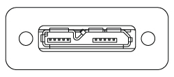
Computer Connection
for BC207 and BC210C Series
USB 3.0 Micro B Connector
Trigger Input for BC210C Series
SMA Female
Do not exceed input voltages between 0.0 V to +5.5 V.
Input Impedance > 100 kΩ
Trigger Input for BC207 Series
BNC Female
Do not exceed input voltages between 0.0 V to +5.5 V.
Input Impedance > 100 kΩ
M2MS(-AL) Extension Sets
Computer Connection
USB 2.0
A USB 2.0 Mini-B to A cable is included with each extension kit.
Optional Connection
USB 2.0
Two USB 2.0 Type A ports are included for connecting the slit beam profilers and one other device, such as the TSP01 USB temperature and humidity controller. The BC207 and BC210C Beam Profilers require USB 3.0 and should not be connected to these ports.
DC Power Supply
15 V / 3 A AC Adapter with a 5.5 mm Outer Diameter DC Connector
Alignment Laser
3.5 mm Mono Jack

Main Window

Click to Enlarge
The main window of the GUI includes the menu bar, tool bar, status bar, and a frame where several windows can be displayed. This screenshot includes several panels: Beam Settings, Calculation Results, 2D Projection, and 3D Profile. The Beam Settings Panel displays all important information in a single location; this panel can be unpinned from the main window and moved to a second location, such as another monitor.
Thorlabs Beam Software for the BC207 and BC210C Series Beam Profilers
- GUI with Adjustable Layout: Windows with Different Measurement Results
can be Rearranged and Resized within the Workspace - 2D and 3D Views of the Beam Profile
- Selectable Overlays such as Peak, Centroid, and Cut Profiles
- 3D View is Fully Rotatable
- M² and Divergence Measurements Compliant with ISO 11146
- Data Export:
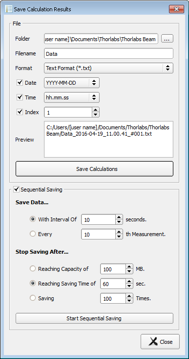
- Results can be Exported from Windows in Different Formats
- Sequential Saving
- Pass/Fail Tests with Customizable, Lockable and Saveable Pass/Fail Parameters
- Power Correction Available for Absolute Power Measurements
- Supports TSP01 for Temperature Logging During Long-Term Measurements
Thorlabs' Camera Beam Profilers, Scanning Slit Beam Profilers, and M² Measurement Systems all use the Thorlabs Beam software package. The screenshots below highlight key features and measurement modes that can be used with our camera beam profilers, including 2D projections of the beam profile and measurement of the beam stability and position. If an M² Extension Set (available below) is added to the system, the software also enables M² and beam divergence measurements.
The latest version of the Beam software package can be downloaded from the Software tab.
2D Projection of the Beam Profile
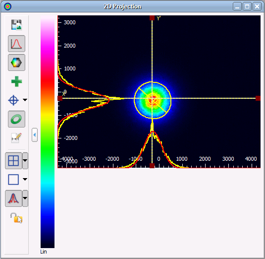
Click to Enlarge
The 2D Projection graph shows the image from the Beam Profiler indicating the power intensity distribution within the selected Region of Interest (ROI). Buttons along the side allow users to save the image, show or hide the x and y scales, mark the centroid or peak positions, and display an approximated Beam Ellipse superimposed on the image.
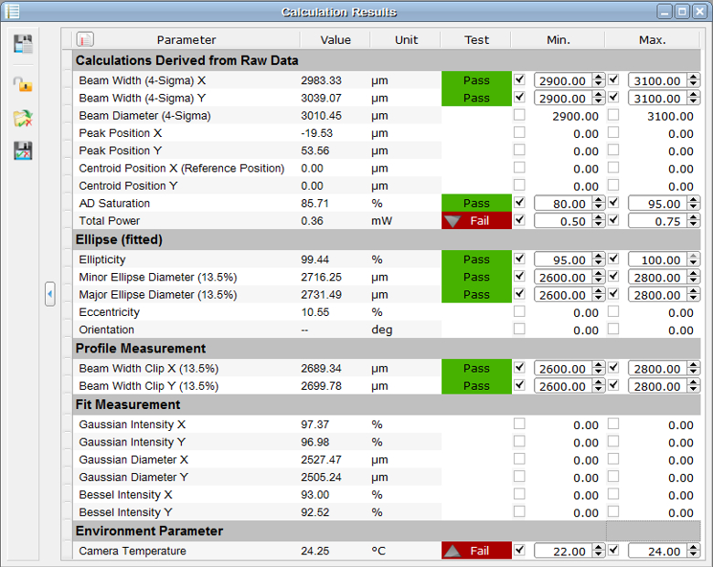
Calculation Results
Beam Stability
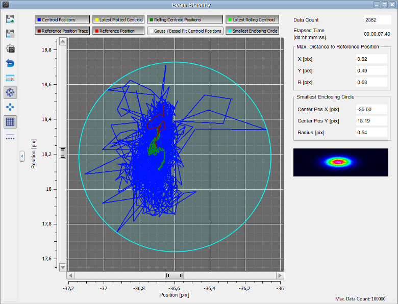
Click to Enlarge
The Beam Stability Window allows the stability versus time to be recorded and viewed. Display options include the Centroid Positions, Latest Plotted Centroid, Rolling Centroid Positions, Reference Positions, and Smallest Enclosing Circle.
Plot Centroid and Peak Positions
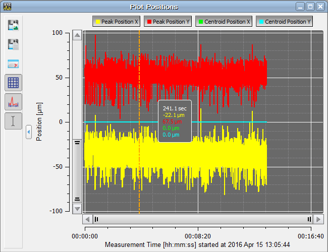
Click to Enlarge
The positions of the X and Y peak and X and Y centroid positions can be displayed as a function of time in this window.
M2 Measurements
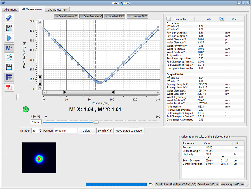
Click to Enlarge
The beam diameter and location of the beam waist are shown after an M² analysis has been performed. Note: This functionality is only enabled when using a beam profiler with one of the M² systems.
Divergence Measurements
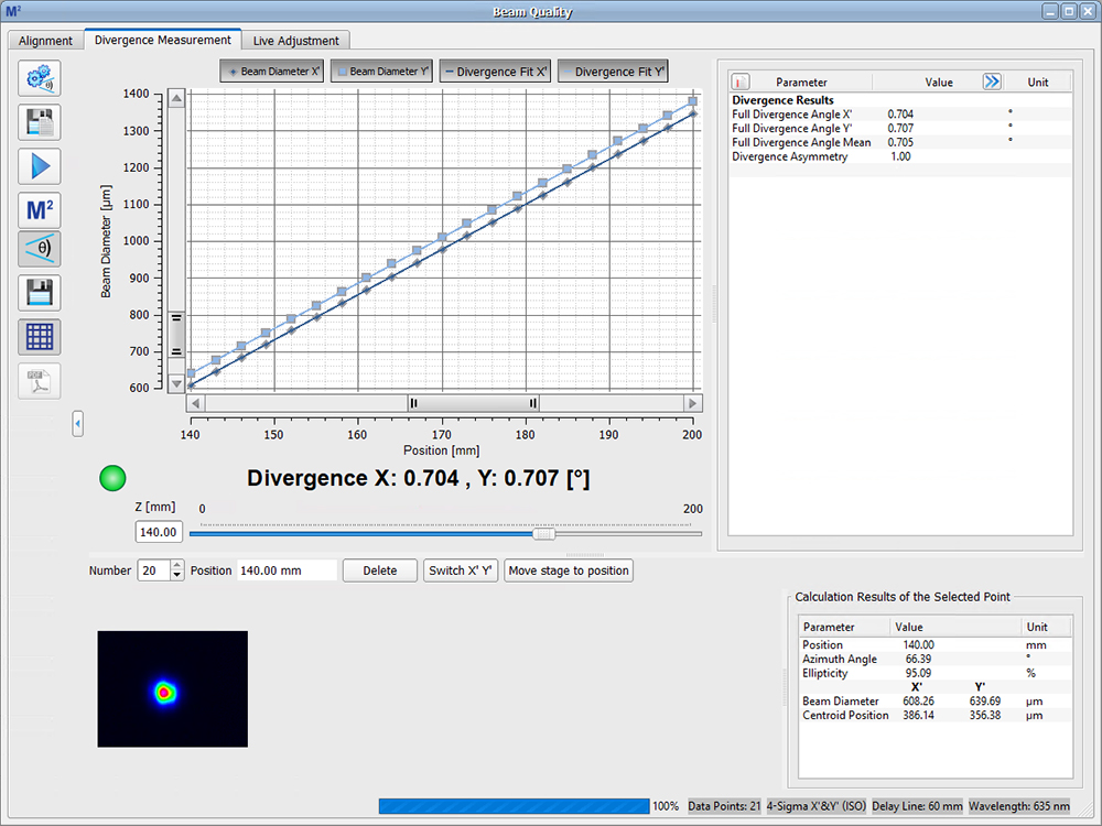
Click to Enlarge
The divergence of the beam is shown after an M² analysis has been performed. Note: This functionality is only enabled when using a beam profiler with one of the M² systems.
| System Requirements | ||
|---|---|---|
| Operating System | Windows® 8.1 (32 Bit or 64 Bit), 10 (32 Bit or 64 Bit), or 11 (for Beam Version 9.0 or Higher) |
|
| Connectivity | Scanning-Slit | USB 2.0 High Speed Port |
| Camera | USB 3.0 High Speed Port | |
| Monitor Resolution | 1024 x 758 Pixel (Min), ≥16 Bit Color Depth | |
| Processor (CPU) | Minimum | ≥3.0 GHz Intel Core (i5 or Higher)a |
| Recommended | Intel Core 2 i5 or AMD Ryzen 5 (3.0 GHz Min) | |
| Memory (RAM) | Minimum | 4.0 GB RAM |
| Recommended | 8.0 GB RAM | |
| Graphics Adapter | Required | OpenGL (Specification GLX 1.3 Up) |
| Minimum | Radeon: X100 Series ≥X850, X1000 Series ≥X1600, HD Series ≥2400; Geforce: 7 Series ≥7600, 8 Series ≥ 8500, 9 Series ≥9600; Quadro: FX Series ≥FX770M |
|
| Recommended | Radeon: HD Series ≥7000; Geforce: GTX Series ≥500; |
|
| Hard Drive | Minimum | 2 GB of Available Disk Space |
Software Packages for Thorlabs' Beam Profilers
The Beam software package can be downloaded by clicking on the Software button below. Please refer to the manual's programming references for interfacing with our beam profilers using LabVIEW™, C, Visual C#, and Python.
BC207 Series Profilers are compatible with Beam version 8.0 or higher. BC210C Series Profilers are compatible with Beam version 9.0 or higher.
Features
- Settings Panel Displays All Important Parameters in a Central Location
- Customizable Calculation Results
- Measured Parameters can be Individually Hidden
- Adjustable Row Heights
- Enhanced Beam Stability Window Measures and Displays the
Smallest Enclosing Circle Around the Centroid Point Cloud
- Alignment Wizard to Aid in Correctly Aligning the M2MS M2 Measurement Systems
- Language Settings of English, German, or Chinese
Software
Version 9.2.6002.614 (February 12, 2025)
Standard full version of software package for 32-bit and 64-bit Windows with driver and graphical user interface for operating the device in standard applications.
| Posted Comments: | |
Rodrigo Vicencio
(posted 2025-05-10 16:25:35.433) Hi, in January I bought this Beam profiler and started to use in March. However, the performance was really bad in terms of processing. I mean, we usually measure different waveguides, sweeping the wavelengths and the positions on a lattice, and the camera has an important delay, which make the beam profiler use a real headache.
I'm using Thorlabs bema profilers since 2009, and in fact the two ones we bought at that time are still working without problems. They work fast and quite perfect I would say. So, we were not expecting to face problems with this.
I would thank you a lot a feedback of which could be a good setting for the camera working fast. I'm using a gamer notebook for this camera and the minimal requirements are really fulfilled.
Also, if it is possible, for example, to buy old beam profilers it would be a perfect solution also for me thinking on future purchases.
Best regards, GBoedecker
(posted 2025-05-12 04:54:01.0) Thank you for your feedback! I will contact you directly for troubleshooting. Jooho Lee
(posted 2025-01-10 09:09:01.01) I am planning to purchase and use the BC210CV/M product.
Can the beam profiler obtain information on other cw lasers except M2MS product?
And when I checked the manual, the BC210 is directly attached to the M2MS and measures the laser from close range. Can I measure it at a distance of about 1m between the BC210 and the laser system?
Please check and reply. hkarpenko
(posted 2025-01-13 12:12:08.0) Dear customer,
thank you for your feedback. The M² system, consisting of a beam profiler and a M² stage, can measure the beam profile and sereval other beam parameters of CW or pulsed sources, which meet the specifications of the system. A short summary of the main specifications is the usage of a maximum average power of 1W, a beam diameter of 20 µm - 10.0 mm and a wavelength of 350 - 1100 nm. I will contact you directly to discuss this further with you, whether this system fulfills your needs. Joachim Kuebel
(posted 2024-12-18 15:05:53.6) I think I found a copy&paste error in the manual on page 10 :) Both tables say "BC207UV(/M) and BC210CU(/M)" while the second table is (I think) for "BC207VIS(/M) and BC210CV(/M)". fmortaheb
(posted 2024-12-19 07:23:02.0) Thank you very much for reaching out to us and pointing out the error. We will edit our manual as soon as possible. Duygu ÇETE
(posted 2024-07-16 22:35:07.373) Bu ürünün nasıl kullanıldığını ve ışın paramterlerini nasıl ölçtüğünü anlayamıyorum lütfen yardım edin.. jjadvani
(posted 2024-07-17 07:46:22.0) Dear Duygyu, Thank you for your feedback. I will contact you directly to provide you further support. voravuth chavai
(posted 2024-03-19 17:53:22.647) Do yo have 3D model for Solidwork 2020 version?, if yes, please send to me.
Thank you in advance. jjadvani
(posted 2024-03-20 03:33:07.0) Dear Voravuth. Thank you for providing feedback. If you click on the red file symbol in the product's documentation, you will get a list of CAD file options that may be beneficial. I will contact you to discuss this further. user
(posted 2024-03-03 12:09:30.913) Hello, I want to save 2d laser beam image and analyse in another development environment. In BC207VIS/M set at full ROI regardless of pixel bining, the saved image always has the dimensions 1097x918 pixels (Thorlabs Beam v. 8.2) . Does this size correspond to the dimensions of the sensor 8.45 mm x 7.07 mm? Best regards. hchow
(posted 2024-03-04 10:29:08.0) Dear User, if you wish to download the full resolution 2D image of your laser beam, you should click "Files", a drop down menu will appear, then click on "Export Device Data," a window will then appear, under the row "Format", click on "Raw" and then save image file. You should be able to download the full image file this way. HA BYEONGHAK
(posted 2024-01-12 17:06:35.81) Dear.
I have this beamprofiler.
My laser specification is as below
- Rep. rate. 0.2 Hz
- wavelength 1543 nm
- Pulse width 5 ns
- Energy : 30 mJ but reflected to beamprofiler is 7%
The laser beam was measured through a beam profiler.
However the beam is measured by the beam profiler the first time, but the laser beam fired once every 5 seconds is measured intermittently thereafter. (Example: Measured 1 time out of 20) hkarpenko
(posted 2024-01-12 08:00:41.0) Dear customer,
thank you very much for your feedback. The problem lies within the duty cycle of the laser. With a higher repetition rate it should be possible to measure the beam more continuous. But be careful with increasing the repetition rate to not exceed the damage threshold of the profiler. I will contact you directly to discuss this issue more detailed with you. Héctor Álvarez
(posted 2023-12-20 12:25:43.553) To whom it may concern,
Is the waist (1/e^2 diameter) measured by the BS207VIS beam profiler the same as the one measured by a CCD camera? I have measured the same beam laser with the BS207VIS and another camera and it is like 15 % smaller than the one measured by the camera.
Is there something to take into account? Am I missing something?
Thank you very much in advance,
Héctor hchow
(posted 2023-12-21 03:18:50.0) Dear Mr. Alvarez, thank you for your enquiry. It seems to me the problem may lie in your BC207VIS or BP209-VIS's beam parameter settings. Since there are a whole host of settings which affects how the beam is interpreted by the respective beam profilers, I will message you personally to see how best to help you. Thank you. Ted Fisher
(posted 2023-06-09 12:59:19.21) Hello, the Thorlabs Beam software keeps crashing on a Win10 laptop. It seems to run fine on a nearby Win11, however that is not close enough to my optics table. Tried rebooting, reinstalling, etc.
The software comes up, but shortly after hitting the Play button, it just disappears.
Is there some log file from the software I could send you?
Thanks for your help. hkarpenko
(posted 2023-06-13 06:38:54.0) Dear Ted,
thank you for your feedback. I contact you directly to discuss this further with you. UNNATI A
(posted 2023-03-03 15:43:55.03) Can Thorlabs' Beam software be used with other normal cameras? wskopalik
(posted 2023-03-06 09:03:21.0) Thank you very much for your feedback!
The Beam software can only be used with the camera beam profilers and the scanning slit beam profilers offered by Thorlabs. Other cameras are not supported by the Beam software. The regular cameras we offer can be used with the ThorCam software.
I will contact you directly to provide further information. Martijn Stok-van Houwelingen
(posted 2023-02-22 12:39:46.663) Compared to the BC106VIS/M, the sensitivity and resolution of the BC207VIS/M is an improvement, but the form factor is very inconvenient when used as a stand-alone camera. We often used our BC106 in a vertical orientation, with the beam coming from the top, where the flat back of the camera (with USB-connection on the side) was perfect. Moreover, the flat form factor was also perfect for measurement in between mirrors, pinholes etc, when space was an issue.
Unfortunately, these advantages are completely gone for the newer BC207, which is very thick and has connections on the back. This makes it much less suitable as an alignment tool, as well as making it very difficult to obtain a beam profile in the vertical orientation, which we use most of the time. hchow
(posted 2023-02-22 08:39:54.0) Dear Mr. van Houwelingen, thank you for your feedback. I will be sure to let our engineers know about what you mentioned here. Marian Hargis
(posted 2023-02-13 16:08:15.943) This camera looks like it could fill the alignment needs we have. However, the price tag falls in the "try before we buy" category. Do you have a demo we could look at? hchow
(posted 2023-02-15 08:29:44.0) Dear Ms. Hargis, thank you for your feedback. I will contact you directly to discuss loan options from us. Thank you. Marian Hargis
(posted 2023-01-12 10:51:14.517) This is very attrative. However, what do you suggest for the NIR range, 1310 - 1600nm? I need both. hkarpenko
(posted 2023-01-13 08:39:50.0) Dear Marian,
thank you for your feedback. For the NIR range, especially 1310nm - 1600nm, one can use the scanning slit beam profiler like model BP209IR1 instead.
I contact you directly to discuss your application further with you. Tian Lan
(posted 2022-11-29 20:39:49.17) Hi! Thorlab Team, I've got a problem in calculating the laser beam diameter, then M2. I've used the BC106N-VIS beam profiler to collect beam intensity profiles at several different distance around the beam waist. What next should I do to figure out the exact laser beam diameter, then M2? I'd like to use both 1/e2 method and 4σ(second moment width)
Looking forward to hearing from you guys. hkarpenko
(posted 2022-11-30 04:35:48.0) Dear Tian,
thank you very much for your feedback. I contact you directly to discuss this with you further. Andrew Lee
(posted 2022-10-24 09:02:47.637) What does it signify when the indicator LED on the camera is blue, its usually green but sometimes goes blue?
I have searched the manual and it only mentions normal operation is green. dpossin
(posted 2022-10-25 05:29:34.0) Dear Andrew,
Thank you for your feedback. At this specific point the manual unfortunately is not entirely right. The blue LED indicates that the beam profiler is connected to an USB3.0 port and the green LED indicates that the beam profiler is connected to an USB2.0 port. user
(posted 2022-08-01 10:37:02.087) Dear Thorlabs team,
I'm using a BC106-UV beam profiler and I would like to control it directly using Matlab. Could you please provide me with some sample Matlab code for the BC106-UV beam profiler? dpossin
(posted 2022-08-02 04:03:07.0) Dear customer,
Thank you for your feedback. I reach out to you in order to provide you with more details. Klay Liu
(posted 2022-07-01 16:07:32.763) BC207VIS have two type:Imperial和Metric
How different are they?
What problems should we pay attention to? soswald
(posted 2022-07-01 07:37:25.0) Dear Klay,
thank you for your feedback. The only difference between the metric BC207VIS/M and the imperial BC207VIS are the mounting holes for post mounting at the bottom of the unit.
The metric version comes with two M6x1mm tapped holes, in the imperial version these are 1/4"-20 tapped. Chen RenHui
(posted 2022-05-30 12:24:34.67) Hello, we would like use the Labview Driver for BC106-VIS BeamProfiler,but I can't find the labview example to BC106,I can only find the labview example for BC2(TLPC2);Please could you send me a full example you had in the past for BC106.I have Labview 2018 running.Thank you.Best regard Renhui. GBoedecker
(posted 2022-05-30 05:22:11.0) Thank you very much for contacting Thorlabs. I contacted you directly to send you the example. allan bereczki
(posted 2022-03-15 15:38:07.38) Does The software for BC207VIS/M performs M2 calculations without the M2MS? I mean utilizing a manual translations stage and imputing z values in the software soswald
(posted 2022-03-24 08:46:19.0) Dear Allan,
thank you for your feedback. The beam software supports manual divergence measurements as described by you, but unfortunately not M² measurements.
Please see Section 5.6.6 Manual Vergence Measurement of the BC207VIS/M manual for further details: https://www.thorlabs.de/drawings/dd7e4d6c1fe68bd5-4BC0DE12-D220-DC0B-913D9956EE4EE590/BC207VIS_M-Manual.pdf John Linden
(posted 2021-08-10 15:15:14.657) Do you have any beam profilers for CO2 lasers? 9.4-10.6 µm wavelengths? soswald
(posted 2021-08-11 08:40:55.0) Dear John,
thank you for your feedback. At the moment we do not offer beam profilers for the 9.4 to 10.6 µm wavelength range.
Please reach out to your local tech support team so we may discuss your application and requirements in more detail. user
(posted 2021-05-22 18:01:32.053) 您好!
在使用贵公司的光束质量分析仪过程中,发现连接电脑后仍没有反应,换过连接线后仍然不行,请问您了解是什么原因嘛? YLohia
(posted 2021-05-24 10:37:47.0) Thank you for contacting Thorlabs. An applications engineer from our team in China (techsupport-cn@thorlabs.com) will discuss this directly with you. Mr. Cui
(posted 2021-01-27 12:01:40.87) Hello, I have purchased the BC106N-VIS/M product. The software can save the images into a picture format (.jpg .bmp etc) from the 2D projection. But I want to analyse the CCD data in other software. How to extract or save the original data of the CCD from this software and save it into txt or dat format? MKiess
(posted 2021-01-27 11:08:40.0) Dear Mr. Cui, thank you very much for your inquiry. If you want to save the measurement data of the X and Y profiles as an XLS or CSV file, first open the corresponding profile via the menu in the Software. In the toolbar of the individual profiles you can now save the measurement data via the save icon. user
(posted 2020-12-23 15:15:47.33) 由于找不到cvirte.dll,无法继续执行代码。 wskopalik
(posted 2020-12-23 07:43:01.0) Thank you very much for your feedback!
The files "cvirte.dll" and "instrsup.dll" are a part of the LabWindow/CVI runtime and can normally be found in these folders when the runtime package is installed: "C:\Windows\System32" or "C:\Windows\SysWOW64"
We will contact you directly to provide further assistance. jin li
(posted 2020-12-23 15:14:58.767) 由于找不到cvirte.dll,无法继续执行代码。
由于找不到instrsup.dll,无法继续执行代码。 wskopalik
(posted 2020-12-23 07:42:15.0) Thank you very much for your feedback!
The files "cvirte.dll" and "instrsup.dll" are a part of the LabWindow/CVI runtime and can normally be found in these folders when the runtime package is installed: "C:\Windows\System32" or "C:\Windows\SysWOW64"
We will contact you directly to provide further assistance. 先生 刘
(posted 2020-12-15 11:18:11.083) 这款可以测单脉冲宽度309fs的的脉冲光吗。 dpossin
(posted 2020-12-16 10:20:39.0) Dear Customer,
Thank you for your feedback. In general it is possible to measure the beam profile of fs lasers as well but this depends on the repetition rate, the beam diameter and the average power. I am reaching out to you in order to check if our beam profilers are suitable for your laser. Ulrich Wetzel
(posted 2020-11-29 11:39:17.49) Hello, we would like use the Labview Driver for BC106-VIS BeamProfiler but after I have installed the software I can find all items in menu (TLBC1, TLPB1 and 2) but no example to BC106-VIS. For BP209 there is one example available (TLPB2) but not for BC106. I have Labview 2015 running. I can remember when I used this software on other Labview version there was one available. Please could you send me a full example you had in the past. Thank you. Best regard Ulrich nreusch
(posted 2020-12-01 09:42:47.0) Thank you for contacting us. I will get back to you via email and send you the respective file. user
(posted 2019-11-18 11:18:19.15) Hi,Has this BC106N-VIS beam profiler an angular dependence, and where is the cutoff ? Is there a degradation of the flux measured for a beam tilted off of 0° from vertical incidence ? dpossin
(posted 2019-11-25 06:12:32.0) Hello Gregory,
Thank you for your feedback. The accepted incidence angle depends on the aperture size. For collimated beams the angles are: 9° @ 9mm aperture, 12° @ 6mm aperture and 14° @ 3mm aperture. The divergence angle has an influence too. I am reaching out to you in order to discuss your inquiry more in detail. 851308587
(posted 2019-03-07 15:11:06.71) Hi,Does this CCD have a step format that can be downloaded?Where can I find it in his website? mmcclure
(posted 2019-03-07 08:48:57.0) Hello, thank you for contacting us. You can view and download the CAD PDF, STEP, and many other files by clicking on the red "Docs" icon to the left of the item number near "Add to Cart". patrick_lee
(posted 2019-02-16 18:25:07.61) Hi, is 20dB, 40dB, 60dB equals to OD2, OD4 and OD6 respectively ? wskopalik
(posted 2019-02-21 02:01:42.0) This is a response from Wolfgang at Thorlabs. Thank you very much for your inquiry!
Yes, this is correct. An attenuation of 20 / 40 / 60 dB equals an optical density (OD) of 2 / 4 / 6. You can see the complete attenuation diagrams of the ND filters which are used in these beam profilers on the website in the tab "ND Filters".
I will contact you directly to provide further assistance. Yahya.elsayed
(posted 2018-11-26 19:06:57.917) Same as comments below worked great then suddenly software doesnt pick up the camera after reconnecting in case a usb is removed. nreusch
(posted 2018-11-30 08:36:50.0) This is a response from Nicola at Thorlabs. Thank you for your inquiry. I have seen that you also contacted your local Tech Support group, who already provided further assistance. In this case, it seems like the beam profiler needs to be repaired. thomas.schnider
(posted 2018-10-10 12:20:41.923) Hi Thorlabs Team, In addtion to all the great feature the beam software has, it would be very usefull to have a video capture function. Currently what I do as a workaround is using a screen recorder software. Appreciated if you internally discuss my suggestion. nreusch
(posted 2018-10-16 05:53:41.0) This is a response from Nicola at Thorlabs. Thank you for your suggestion and for sharing your workaround! We might not be able to implement that in the near future, but I will contact you directly to better understand the requirements of your specific application. ccheng
(posted 2018-08-06 12:28:39.393) Hi,
The beam image exhibits a "scratch" on one of our cameras. I am wondering how to take apart to inspect the array or the back side of the #1 attenuator. Could you send me an instruction? Thanks a lot. swick
(posted 2018-08-08 06:08:17.0) This is a response from Sebastian at Thorlabs. Thank you for the inquiry.
In order to inspect the backside of the ND Filters you can remove the ND- Filter Wheel. Instructions for this can be found in the manual at chapter 3.2. I contacted you directly for further assistance. emanuele.polino
(posted 2018-07-04 16:31:07.09) Dear Thorlabs team, We have a BC106N-VIS/M , and since now, after months, it worked well. Yesterday we disconnected the camera from pc and reconnecting it just after, the camera can't be seen by the software. We tried with different computers, connection cables, and reinstalled softwares, but the device, although it is visible in the pc it is not seen in the software, neither when we try to refresh ''Device Selection''. Light is green. Have you any suggestion to solve this problem? swick
(posted 2018-07-06 04:21:52.0) This is a response from Sebastian at Thorlabs. Thank you for the inquiry. I contacted you directly for troubleshooting. gdamerose
(posted 2018-02-07 10:49:41.99) Dear Thorlabs team, I ordered a BC106N-UV last june, and since it worked great on same laptop computer. But today, I cannot mahe it work. When I open software no informations is displayed in ''Beam Profiler Information'' nether when I try to refresh ''Device Selection''. I tried different USB cables, 3 PCs and software update from last november found on your website. Light is green and driver seems to install correctly. Is it a call for a RMA, please help, thank you. wskopalik
(posted 2018-02-08 03:04:52.0) This is a response from Wolfgang at Thorlabs. Thank you very much for your inquiry!
I will contact you directly to provide further assistance with this issue. We will probably need to make an RMA in this case. himics.laszlo
(posted 2017-11-17 12:12:09.42) The recently ordered BC106N-VIS/M is not working properly. First, it was hard to install (the connection between notebook and device was feasible only on the 3rd computer). Secondly, it regularly loses the connection with Thorlabs Beam 7.0 software and to reconnect takes more than 1 hour or even it is not possible for a long time. What can be wrong? In my opinion, it is due to some electronic contact problem, but I am not sure. wskopalik
(posted 2017-11-22 03:29:45.0) This is a response from Wolfgang at Thorlabs. Thank you very much for your inquiry!
Issues like this can be caused if the beam profiler doesn't get enough power from the USB port which can e.g. be due to a bad USB cable or also an issue with the USB port.
I will contact you directly to troubleshoot this issue in more detail. tim.cyr
(posted 2017-10-25 16:34:05.203) Where can a find a downloadable spec/user manual for the BC106 beam profiler? I see the web pages, but I don't see any links to any downloadable documentation (other than the software). I don't want to be a slave to the web or have to download all the charts and such piecemeal. wskopalik
(posted 2017-10-26 05:53:01.0) This is a response from Wolfgang at Thorlabs. Thank you very much for your inquiry.
You can find all the available documents when you click on the red document icon left of the part number in the overview tab of this website. This will open a pop-up window with links to the documents. For all other products on the website this is the same.
I will also contact you directly. dmkim
(posted 2017-10-03 14:59:41.893) On a new windows 7 install, I get the error on ver 7 when I try to launch it for the first time:
"The application was unable to start correctly (0xc000007b). Click OK to close the application". Also tried ver 6.2b. swick
(posted 2017-10-05 03:39:46.0) This is a response from Sebastian at Thorlabs. Thank you for the inquiry.
I have contacted you directly for troubleshooting. user
(posted 2017-07-24 10:58:06.493) More mounting options would be nice. It's difficult to use the BC106N with any kind of lens tube or cage system.
The other cameras are nicer in that regard. The BC106N is overkill for a lot of beam measurements, but unfortunately it's the only windowless camera you have and the only one that works with your beam profiling software (I think). swick
(posted 2017-07-28 03:21:45.0) This is a response from Sebastian at Thorlabs. Thank you very much for the feedback.
At the time for BC106N, lens tubes and cage systems can only be attached via SM05 thread at the filter wheel.
We offer some cameras with removable window (e.g. DCC1545M or DCU223M), however, at the time it can not be used with our Beam Profiler software.
We will internally discuss your suggestions. itay.bloch.m
(posted 2017-07-09 16:53:37.353) Dear Thorlabs,
I have the BC106N-VIS/M, and I have ecountered a simple yet very annoying problem when using the product.
The cable provided with the product is rather short, and when I try to use an extending cable- the connection either doesn't work, or is only able to pass frame per 0.5 sec (instead of at least 10 frames per sec).
I have tried dozens of different extention cables, as well as more elaborate ones that have additional power input-but to no avail. I have the same problem with my beam profiler (BP209-vis/M).
I was wondering whether you have an official USB extention cord, or can give me another solution.
Thanks and Best Regards wskopalik
(posted 2017-07-10 05:14:44.0) This is a response from Wolfgang at Thorlabs. Thank you very much for your inquiry.
The camera as well as the scanning slit beam profilers are indeed quite sensitive when it comes to the USB connection. We have a longer USB cable which is normally included with the M2 measurement system and has been tested with these profilers. It has a length of 3.0 m as opposed to the included cable which is only 1.5 m long.
I will contact you directly to send you cables of this type for the profilers you have. We will also change the bill of material for these profilers so the longer cable will be included in the future. asha
(posted 2017-06-25 21:13:32.27) The price of the equipment is listed to be $4,295.00. Does this price cover the software cost also. Thanks wskopalik
(posted 2017-06-26 04:16:31.0) This is a response from Wolfgang at Thorlabs. Thank you very much for your inquiry.
The software for Thorlabs' beam profilers is free of charge. You can download it here on the website in the tab "Software". It works with our camera profilers as well as our scanning slit profilers.
I have contacted you directly to provide further assistance. dirk.lorenser
(posted 2016-12-23 14:42:26.017) I used to have a Spiricon beamprofiler with a Si image sensor which surprisingly worked quite well beyond the 1100nm bandgap limit for Silicon due to some weird parasitic effects in the semiconductor. The responsivity was much lower than in the wavelength range below 1100nm but we used it successfully to beam profile at 1300nm wavelengths for OCT systems. Have you ever tested if your CCD also responds to 1300nm beams ? The parasitic responsivity drops off quite sharp around 1320nm, so you need to test a light source that has some spectral power below 1320nm. wskopalik
(posted 2016-12-23 08:14:11.0) This is a response from Wolfgang at Thorlabs. Thank you for the inquiry.
The BC106N-VIS has been tested at 1310nm. It still has a slight responsivity there which is however orders of magnitude lower than in the specified range (i.e. 350 - 1100 nm). Beams with enough power could still be measured, but we can't tell how accurate these measurements would be. For accurate measurements we cannot recommend to use the BC106N profilers outside of their specified wavelength ranges.
I have contacted you directly to discuss this in more detail. songminsoo
(posted 2016-10-07 15:51:08.727) Few months ago, I bought BC106N-VIS/M through Korea vendor 'AInnoTech'. Untill last week, we didn't use it, and this week we tried to use it after install S/W ver.6.2. But we got a trouble.
This S/W can't display 2D or 3D image. When detector is illuminated by laser beam which has 1 mm of diameter, only measurement in X-axis work well, not in Y-axis. In Y-axis, S/W shows that it is ~6 mm of diameter everytime. If the laser beam is rotated by 90 degree, even S/W shows that 1 mm diameter in X-axis, and 6 mm diamter in Y-axis. Please let me know the solution. swick
(posted 2016-10-07 03:17:19.0) This is a response from Sebastian at Thorlabs. Thank you for the inquiry.
The software of our Beam Profilers, Thorlabs Beam, can display beam profiles in 2D and 3D. For this please see manual on page 59 and 61.
I have contacted you directly for troubleshooting and assistance. 425216406
(posted 2016-08-18 15:43:45.44) Dear Thorlabs-Team, as requested in a previous post: I would like to read out the BC106N-VIS from MATLAB. Would you mind to send me some information on how to read out the beam profiler via a serial connection (or otherwise). If you do not have MATLAB code available I also appreciate any general input on how to do it (or C/C++ code). Thanks very much in advance!
Newman swick
(posted 2016-08-18 04:48:19.0) This is are response from Sebastian at Thorlabs. Thank you for your inquiry. Unfortunately we have no MATLAB example code available at the time but can provide codes for other applications which can be converted with the beam profiler driver and commands to a beam profiler suitable application. We will contact you directly to provide more information on how to do that and send you an example code in C_sharp. clesch
(posted 2016-05-24 14:05:16.643) Dear Madam or Sir,
I'd like to know whether it is possible to measure the beam profile in real time, or at least get an estimate in real time, with this product and if, at which speed (i.e. framerate).
Kind regards
Clemens Schäfermeier
DTU Physics shallwig
(posted 2016-05-25 03:19:56.0) This is are response from Stefan at Thorlabs. Thank you for your inquiry. It is possible to measure the beam profile in real time. We specify for the camera a maximum frame rate of 10 fps at full resolution (1360 x 1024 pixel). At 640 x 480 pix >27 fps and at 320 x 240 pix >43 fps. Please note that these frame rates are highly depending on PC processor and graphic adapter performance.
I will contact you directly to discuss your application in more detail. sean-mattingly
(posted 2016-02-29 14:09:09.023) First of all, this beam profiler is great. Excellent software API and resolution at the price. Newport doesn't even offer an API of this scale for their profilers!
I have a technical question about using the software API of this beam profiler. Does there exist a solution in which I can readout using a C or C++ API results from the camera while the included Thorlabs Beam program is running?
I have implemented a process which uses Windows RPC in order to acquire laser data remotely with this beam profiler, using the static .libs in IVI Foundation. Unfortunately, when this program is open, the beam profiler cannot be connected to with Thorlabs Beam, since my C++ RPC server has made its own connection. As a result, I must shut down my RPC server in order to view the beam using Thorlabs Beam.
I ask since I would like to be able to monitor the beam profiler data in real time while I am pulling it. Perhaps there is a shared memory .dll file the Thorlabs Beam program uses I could dynamically link to? shallwig
(posted 2016-03-03 09:22:32.0) This is a response from Stefan at Thorlabs. Thank you very much for your feedback and your inquiry. It is only possible controlling the beam profiler from one program instance at the same time. But it is possible to stream the calculation results by using the “network variables”. This feature is a data interface for handing over to an external program environment the following parameters: saturation, total power, centroid positions X and Y, 4-sigma width X and Y.
The “Sequential Saving” feature also allows you to save images which could be used in another program environment for further analysis. This way the GUI can be used while pulling data at the same time. I will contact you directly to check which data you need and check your application in more detail. john.sandford-oneill
(posted 2016-02-25 10:27:15.233) I have a problem with this beam profiler/accompanying software. When saving a 2D projection the images do not have the same number of pixels as the size of the CCD even though the full size of the detector is selected. Are the images being scaled? This makes it difficult to analyse these images in other software. shallwig
(posted 2016-02-25 11:26:27.0) This is a response from Stefan at Thorlabs. Thank you very much for your inquiry. The images saved directly from the 2D projection window get scaled but you can also save the raw images by using the export function. It is described in the manual on page 74 how to do that. http://www.thorlabs.com/thorcat/MTN/BC106N-UV-Manual.pdf Here you can select between . raw .bmp and . tiff to save the true data for further analysis. I will contact you directly to check if you have any further questions. tabitha.a.joiner
(posted 2016-02-10 09:12:50.083) Where is this product manufactured? I need to comply with the Buy American Act. shallwig
(posted 2016-02-11 06:27:35.0) This is a response from Stefan at Thorlabs. Thank you very much for your inquiry. The Camera as well as the Slit beam profilers get manufactured in Germany. I will contact directly to check any further questions. fcouweleers
(posted 2015-12-14 10:25:07.997) the specs say that the distance from sensor distance to surface is 16.7mm but also that it is 6.65"?
the drawing says that the distance is 12.2mm? shallwig
(posted 2015-12-14 09:10:41.0) This is a response from Stefan at Thorlabs. Thank you very much for your feedback. The distance in the Specs on our website is a typo. The correct distance is 12.2mm as shown in the drawing. We will correct that. I will contact you and check if you have any further questions. wchill
(posted 2015-09-30 21:27:46.013) I'm having a recognition problem with my BC-106VIS (the older type with 4 filter slots on the wheel). It has worked for months (including this morning), but now the BEAM 6.0 software does not recognize the device. My computer does- it is plugged in and has power (the light is on), and if I go into Windows Device Manager it recognizes the device as "BC106 Camera Beam Profiler".
I've restarted the computer, and at the request of a technical representative via phone, I've uninstalled and reinstalled the software and drivers with no luck. Only one time I received an error message regarding an issue with device firmware (unfortunately I did not write down the message).
Is there a way to update the firmware beyond the method listed in the manual (for hot pixel correction)? I cannot access the device manager in Beam 6.0 since the device is not recognized by the software, so I need to update the firmware using a different method. Thanks! shallwig
(posted 2015-10-01 09:08:54.0) This is a response from Stefan at Thorlabs. Thank you very much for your feedback and please apologize the problems you face your BC106 Camera Beam Profiler. I will contact you directly to troubleshoot this in more detail. ian.howard
(posted 2015-08-12 11:24:11.863) Have a problem with hot Pixel correction.
Using Thorlabs Beam Software with newly purchased BC106N, the Firmware Version of the camera is recognized as 13.13. The Manual states that 13.20 is required for hot Pixel correction. However the Software allows me to use/start correction then throws up an error rather than offering me a link to upgrade Firmware. How can I upgrade Firmware manually to resolve this problem?
Thanks shallwig
(posted 2015-08-12 09:55:21.0) This is a response from Stefan at Thorlabs. Thank you very much for your inquiry. I am sorry for the problems you face with our beam profiler here. For beam profilers with FW 13.13 installed the firmware update dialog is supposed to pop up when you check the hot pixel correction in the software as described in the manual on page 61 and click “update Firmware”. I will contact you directly to check the error message which pops up in your case and how this can be solved. yongsoo.lee
(posted 2015-06-18 01:02:51.75) I bought your CCD camera OS of my pc is windows7 64bit.
After installing the SW, runtime error r6030 was happend.
How can I solve this problem. shallwig
(posted 2015-06-18 05:47:32.0) This is a response from Stefan at Thorlabs. Thank you very much for your inquiry and pleas apologize the problems you face with the beam profiler software. The runtime error r6030 can occur on Japanese and Chinese operating systems when Microsoft office is installed. This error is caused by changing the input method editor (IME) after installation of MSOffice 2010. In the manual on page 143 http://www.thorlabs.de/thorcat/MTN/BC106N-UV-Manual.pdf you can find a screenshot showing how to resolve this by setting the IME back to standard Microsoft IME. I will contact you directly to troubleshoot this in more detail. johan.stigwall
(posted 2015-06-15 18:05:42.657) Hi, just like the previous poster I would also like to read out the beam profiler image using Matlab. shallwig
(posted 2015-06-17 06:22:47.0) This is a response from Stefan at Thorlabs. Thank you very much for your inquiry. Unfortunately there is no MATLAB example code available so far but we have codes for other applications which can be converted with the beam profiler driver and commands to a beam profiler suitable application. We will contact you directly to provide you with more information how to do that in detail. alexludwig.klein
(posted 2015-05-09 02:01:00.093) Dear Thorlabs-Team,
as requested in a previous post: I would like to read out the BC106N-VIS from MATLAB. Would you mind to send me some information on how to read out the beam profiler via a serial connection (or otherwise). If you do not have MATLAB code available I also appreciate any general input on how to do it (or C/C++ code).
Thanks very much in advance!
Alexander tschalk
(posted 2015-05-11 05:26:33.0) This is a response from Thomas at Thorlabs. Thank you very much for your inquiry. After installing the beam software you can find a C example in the following location of your computer: C:\Program Files (x86)\IVI Foundation\VISA\WinNT\TLBC1\Examples. A Matlab code is currently not available but i will contact you directly with more detailed information. n.bayarjargal
(posted 2015-03-03 02:47:59.75) Dear Thorlabs,
I would like to report on malfunctioning of the software version 6.
1. I wanted to save image by using File -> Export device data when the Device setting window is open, unfortunately, this results in sudden close of the whole software.
Hoping that you could fix this error, I'm sending the error message which is "ThorlabsBeamApplication.exe has encountered a problem and needs to close." Error codes are:
AppVer: 6.0.785.2502
ModName: bc1source.dll
ModVer: 6.0.785.2502
Offset: 000086f0
This never happened to previous versions such as 4.0. When Device setting window is closed, Export device data works well. But it is useful to have them both open which was the case in V4.0.
2. When I try to save image by using Save in 2D Projection window, it re-scales and save the image. This is not acceptable and completely misleading when you want to have the raw data of your experiment. I think it should save the raw data or at least you could give us option to choose.
3. Can you please tell me how the Spectrum color scale correlates to the Gray scale image? Apparently your the Spectrum color scaling doesn't match with Matlab jet color scale. So when you accidentally obtain image with Spectrum color scale, there is no way to convert it to Gray scale.
Thank you very much for your help in advance.
Sincerely,
Bayarjargal shallwig
(posted 2015-03-09 04:41:43.0) This is a response from Stefan at Thorlabs. Thank you very much for your feedback. The sudden close of the software when using the export device function with open device setting window is a bug we fixed already. I will send you a link from where you can download a version where this bug is fixed. To your second inquiry, we are working on a new implementation which will allow you to save the 2D projection without this reescalation. So that you can choose between raw data and a rescaled image as you suggested. Thank you for this hint. Regarding your third inquiry, you can find under the following path C:\Program Files\Thorlabs\Beam\LUTs .lut files which are ordinary text file with nine columns and 256 rows. The first three columns have 256 entries, the last six columns only 129. Each value represents a 8 bit intensity (0- 255) of R(ed), G(reen) and B(lue), respectively. The first three columns represent the linear scale of a user-made color scale, the next three columns the logarithmic scale and the last three columns the quad scale.
In the software in the application settings you can choose the color scale and between logarithmic, linear and Quad (see page 73 in the manual http://www.thorlabs.com/thorcat/MTN/BC106N-UV-Manual.pdf) From the corresponding .lut file you can copy the RGB values into a new .txt file and make the grey scale assignment for each pixel.
Thank you again for this valuable feedback, I have contacted you directly to discuss your inquiries in more detail. smh231
(posted 2014-12-01 16:28:50.85) I have the same issue as described below
on labview 2013 (windows 7) the beam software works correctly but on running the labview sample software no devices are detected (with the beam software off).
Any assistance would be appreciated. shallwig
(posted 2014-12-02 05:21:10.0) This is a response from Stefan at Thorlabs. Thank you very much for your inquiry. We have contacted you directly to troubleshoot this problem. alexkorom
(posted 2013-07-02 20:40:52.173) alexkorom@gmail.com
tschalk please send me Labview VI sample for Thorlabs Beam 5.0 BC-106-vis,
Poster: tschalk
Posted Date: 2013-01-04 11:53:00.0
This is a response from Thomas at Thorlabs. Thank you very much for your inquiry. If you are using the software Thorlabs Beam 4.0 than the LabVIEW VIs are located here: C:\Users\User\Documents\Thorlabs\Thorlabs Beam\Samples\ThorlabsBeamSampleLabView. If you are using the advanced beta version I can send the VIs via email. tschalk
(posted 2013-07-03 05:41:00.0) This is a response from Thomas at Thorlabs. Thank you very much for your inquiry. I will send you the VIs via email. user
(posted 2013-06-27 10:10:41.85) - Version 5.0
The software is not being able to calibrate saturation level on its own. It was better in 4.0, but now I how to decrease exp.t manually so that the sensor is not saturated.
- When saving images with "export" from File menu, It automatically disables the use of all other menus. I think I should be able to toggle between saving pop up screen and other pop ups simultaneously without closing the saving pop-up. tschalk
(posted 2013-07-02 05:15:00.0) This is a response from Thomas at Thorlabs. Thank you very much for your inquiry. If you enable the function "auto exposure control" the exposure time is set automatically by the software. Regarding the file export, we will enable the functionality to toggle between the saving screen and other screens in future versions of the beam software. If you have any additional questions please contact me under europe@thorlabs.com. hbhudi
(posted 2013-04-29 22:38:19.017) I meet a problem after using it for a while. The software 'Thorlabs Beams 5.0' shows 'the device has been moved' whenever I start to configure the 'device setting'. Can you help me out of this? Thanks jvigroux
(posted 2013-04-30 11:50:00.0) a response from Julien at Thorlabs: thank you for your message. This error could have several potential origin and could be related either to a hardware problem or to a software one. I will contact you directly to help solving the problem. john.f.burris
(posted 2013-03-19 10:32:03.887) I have a bc-106-uv beam profiler and would like to know what the maximum peak power/ per pulse energy is for beams incident on the 40dB filter and the bare detector. The ranges given in 7.4.1(p149) and on the chart in 3.4.9 (p75) appear to be for CW and not pulsed operation.
John Burris
Code 694
Goddard Space Flight Center jlow
(posted 2013-03-21 16:10:00.0) Response from Jeremy at Thorlabs: Unfortunately we do not have data about the damage threshold for pulsed lasers. We will get in contact with you to discuss about your application in more detail. hadi.abidin
(posted 2013-02-11 15:14:50.523) Is the BC106-VIS+ M² Beam analysis can withstand vacuum enviroment(ie 100mBar). Thank you tschalk
(posted 2013-01-04 11:53:00.0) This is a response from Thomas at Thorlabs. Thank you very much for your inquiry. If you are using the software Thorlabs Beam 4.0 than the LabVIEW VIs are located here: C:\Users\User\Documents\Thorlabs\Thorlabs Beam\Samples\ThorlabsBeamSampleLabView. If you are using the advanced beta version I can send the VIs via email. arrow167
(posted 2013-01-04 03:58:00.23) Where can i find labview drivers for BC106 beam profiler? Could you send me these files to e-mail? Thank you. jvigroux
(posted 2012-12-03 08:11:00.0) A response from Julien at Thorlabs: Thank you for your feedback. We have created a new software version including the plugin also in the debug state. I will send you this version and we will upload it on our website as release candidate in the next few days. ebenson
(posted 2012-11-28 23:54:13.413) I have run into a problem trying to use the IBeamProfiler plugin. I am using Qt with mingw, the plugin was compiled in Qt using MSVC. I get an “incompatible plugin” error when trying to load it since Qt requires the plugin to match the application in Qt version, compiler type and release/debug state also.
I have installed the LabWindows/CVI runtime (from nilwcvirte2010sp1.exe) but there is no GUI or application that allows me to see or configure the NI variables. Do you have a code snippet in C that shows me how to access the ThorlabsBeam NI variables? jlow
(posted 2012-08-28 11:39:00.0) Response from Jeremy at Thorlabs: We do not have MatLab sample code but we do have a sample code for C++. I will get in contact with you directly on some resources on converting C++ code to MatLab. danylopfiqui
(posted 2012-08-27 17:05:46.0) Hello. I would like to operate the BC106-VIS profiler from a windows platform and MATLAB, via USB. I don't understand how to proceed, and the documentation does not help much. I just need to establish a serial port connection, command the camera parameters (expodure time, gain), and trigger picture acquisition and transfer to the computer... how can I do that, or where can I find information ? Thanks, Dany. jvigroux
(posted 2012-05-29 11:11:00.0) a response from Julien at Thorlabs: Thank you for your feedback! There is no direct way to use the software together with another application simultaneously when both of them are connected to the same beam profiler. To palliate this problem, we implemented in the software the possibility to work with NI variables. Those variables can be pushed to a third party program or application when the software is running and can thus be used as an input for further calculations and modifications. ebenson
(posted 2012-05-28 03:12:58.0) I am connecting to the camera using the ThorlabsBeamLibrary.dll. To do this the ThorlabsBeamApplication must be shutdown. Is there a way to have both function simultaneously so that I can save data with my custom application and the user can interact with the GUI to setup the experiment (for example a sockets server). As a minimum is there a disconnect button in the ThorlabsBeamApplication to toggle the camera connection state? jvigroux
(posted 2012-04-20 10:33:00.0) a response from Julien at Thorlabs: Thank you for your feedback! the Labview example should normally work fine. In order to help wit the troubleshooting, we would need to know what is the Labview version that you use, and what is the exact error message you get, if you get one. I will contact you directly to check on those point. stephan.fieberg
(posted 2012-04-20 03:44:14.0) Hi, I have the same Problem as ville.hautala. In Labview (2010) the ThorlabsBeamLabviewSample.vi usually can't connect to the beamprofiler, although Thorlabs Beam 4.0 can. It once was connected and now I cannot get it connected again. tcohen
(posted 2012-03-09 19:40:00.0) Response from Tim at Thorlabs: Thank you for contacting us. I have contacted you directly to troubleshoot. ville.hautala
(posted 2012-03-09 02:57:21.0) Hi, I have problem with the LabView VIs. Connecting with Thorlabs Beam 4.0 software to the camera device allways works, but when I try using ThorlabsBeamLabViewSample.vi Labview can't find any devices. I have managed to establish connection to camera and get everything working few times, but most of the times connection cannot be made. Disconnecting camera or rebooting computer does not help. I also tryed 4.1 beta version and Thorlabs beam 4.1 software again works. This time Labview did manage to find camera, but init device failed allways. I'm using Labview 2011. It would be also very good to add all the VIs to ThorlabsBeamLabviewSample.vi to make testing and building own applications easier. It is currently missing all the control VIs like Change Clip Level. bdada
(posted 2012-02-10 19:03:00.0) Response from Buki at Thorlabs to Theisen-Kunde:
Thank you for your feedback. We have contacted you to provide assistance. Theisen-Kunde
(posted 2012-02-10 09:05:30.0) To whom it may concern.
The data export from the 2D plot gives always no real data. It looks more like noise signals. Pixel value is OK. On the plot a nice shape is visible. No differences between .txt or .xls. Is it comma or dot for the number value decimal point?
Best regards Dirk jvigroux
(posted 2011-12-12 07:28:00.0) A response from Julien at Thorlabs to dwy101: Thank you for your message. The latest software version for the beam profiler can be downloaded directly from our beta software page, which is directly accessible form the main product page of the CCD beam profiler. We will contact you directly to send you the different links you need. jvigroux
(posted 2011-12-12 07:25:00.0) A response form Julien at Thorlabs: Thank you for your feedback. The aperture size is indeed to be understood as the sensor size. We will modify the website according to your comments. user
(posted 2011-12-11 21:20:50.0) Please clearly state the sensor size, looked around and only found "Maximum Aperture Size" which is ambiguous. Ideally this information would be one of the main bullets. jvigroux
(posted 2011-11-16 13:11:00.0) A response from Julien at Thorlabs: Hello! thank you for your message. The latest software version for the beam profiler can be downloaded directly from our beta software page, which is directly accessible form the main product page of the CCD beam profiler. We will contact you directly to send you the different links you need. dwy101
(posted 2011-11-16 22:23:23.0) Hello,Dear Julien. I have justly buy a BC106-UV beam profiler and need to use LabView to control the device.i am not familiar with the usage of it, but from the last feedback,i known that only the lastest version software(V4.1.144)can set the exposure time. i am urgently to know how can i get the newest version software. the free down load in your web was only the version 4.0.188. jvigroux
(posted 2011-09-14 10:58:00.0) A response from Julien at Thorlabs: Dear Pawel, thank you for your feedback. We have modified the Labview driver so that they now include functions to set the gain and exposure time. Those will be included into our beta software package but this might take a couple of days. I will thus send you the extra VIs per email. noday
(posted 2011-09-12 14:25:01.0) Hello, I am using BC106-UV beam profiler and I am very pleased with both the product and the Thorlabs Beam software. However, for my application I need to use LabView to contact with the device and here it does not look so good, unfortunately. Provided LabView drivers cover only small part of the Thorlabs Beam program functionality. The most missing thing is the possibility to control the exposure time and sensor gain, which makes LabView use very difficult. Since the LabView drivers are based on the DLL libraries with no documentation provided, it is also hard to develop drivers by my own. I would be really happy if there was a possibility to control the exposure time (and perhaps gain) from the LabView environment. Best regards, Pawel. jvigroux
(posted 2011-07-19 14:03:00.0) A response from Julien at Thorlabs: Dear Bayarjargal, thank you for your feedback! Our software is currently written such that the power display does not dynamically modify the unit range. As a result, even though a power is detected, it can be that the displayed power is zero if the measured power is smaller than the smallest power increment of the power display. The easiest way around this limitation is simply to manually change the unit from mW to dBm. due to the logarithmic nature of this unit, very broad dynamic ranges can be easily displayed. A fix for the limitation you addressed will be implemented in our next software release. n.bayarjargal
(posted 2011-07-15 04:37:27.0) Hello, Dear Thorlabs Engineers
Currently Im using beam profiler BC106-VIS and I have a problem with power value reading.
When I set the power setting to mW, Im not being able to read low level of total power. On 2D projection screen I can see the beam shape, but on the calculation result window the total power value is being 0 all the time. How can I change the setting on software so that I can detect microwatt? I would appriciate if the beam profiler can give a total power value which is close to the accurate value. For more exact value I could use powermeter, but for rough estimation I would love to rely on beam profiler.
Have a nice day,
Thanks a lot for your help in advance.
Sincerely,
Bayarjargal Narantsatsralt jvigroux
(posted 2011-06-03 11:01:00.0) A response form Julien at Thorlabs: Sorry about this labeling error. We will correct it and include the proper unit in the next software release. Thank you very much for your feedback! mgrabowski
(posted 2011-06-02 11:38:41.0) Hi, I have been outputting the data from the Profiler and Ive noticed just a little label issue. The Gaussian Diameter in the program (Calculation Results window) is in units of microns. However, the units stated in the text file output states [%]. That threw me for a loop today, so I thought I would let you know. I dont see any problem with the data, just the label.
Thanks! jjurado
(posted 2011-04-19 11:22:00.0) Response from Javier at Thorlabs to alee: Thank you very much for contacting us with your request. Below are the answers to your questions:
(1) As it possible to sequentially save the data from the x and y plots not just the image? In the version 4.0 it is not possible to sequential save the X-Y-Profile data. We will integrate it with the next version.
(2)The software always crashes after 2 to 3 days of operation reporting its lost the camera, could you tell me what might be causing this? Another option for me would be using the hardware trigger and triggering every hour and saving every image instead of continuously sampling and asking the software to save an image every hour, do you think this would solve the problem?
One of our engineers will reproduce this behavior and will give feedback if it helps to trigger the camera instead of saving every hour.
(3) Is there a way to remove the Gaussian fits from the 2d and 3d profile images?
Currently there is not. We will integrate a button to hide the Gaussian fit profile.
We will contact you directly once we have finalized testing the beam profiler. alee
(posted 2011-04-18 18:10:41.0) Ive been using the new version 4 and have a few questions,
1)Ive been using the sequential saving for images, is it possible to sequentially save the data from the x and y plots not just the image?
2)Im interested in longterm stability and have been using the sequential saving to save 2d and 3d profiles every hour, however the software always crashes after 2 to 3 days of operation reporting its lost the camera, could you tell me what might be causing this? Another option for me would be using the hardware trigger and trigering every hour and saving every image instead of continuosly sampling and asking the softwre to save an image every hour, do you think this would solve the problem?
3) is there a way to remove the gaussian fits from the 2d and 3d profile images
Thanks tor
(posted 2010-11-29 08:13:02.0) Response from Tor at Thorlabs to Joe: Thank you for your interest in out BC106-UV. I will send you the STEP file shortly. Joe.Williams
(posted 2010-11-25 09:31:51.0) Could you please send me a STEP file of the BC106-UV Camera Beam Profiler.
Many thanks
Joe jhartmann
(posted 2009-11-18 10:57:23.0) A response from Juergen at Thorlabs to sgrabtchak: With the current new SW version (2.0), that should work - it seems, you have the predecessor.
There is a possibility to export measured (not the fitted!) X and Y profile data.
Measured data can be saved either normalized to peak value, where peak is considered 100%, or to the max. available number of values (8 bit = 255 = 100% or at 12bit 4095 = 100%).
How to normalize, e.g. "Autoscale to peak", can be adjusted in Application Settings.
If you need to save additionally fitted values, we can build that in the next SW version.
If you need a download link to 2.0 SW version, please let me know. sgrabtchak
(posted 2009-11-17 17:39:10.0) Id like to be able to save raw and calculated data points for X- and Y- profiles. However, I couldnt find an option in the program that would allow me to do it. (I could only save so called "computed results".) Please, let me know if its possible.
Serge jhartmann
(posted 2009-11-13 11:40:43.0) A response from Juergen at Thorlabs to zhuling:
Could you please let me know, what you mean, saying:
"However, I can not get the smooth Gaussian profiler as you set in the machine before"
Also, please let me know closer details on your lasers (both UV and VIS):
- wavelength?
- pulsed or CW?
- optical power incident to BC106-UV?
- beam Ø?
- used ND filter?
- what is the very problem you experience? zhuling
(posted 2009-11-10 01:45:48.0) I have used the profiler (BC106-UV) to measure both the visible laser and the UV laser. However, I can not get the smooth Gaussian profiler as you set in the machine before. jens
(posted 2009-06-18 18:52:23.0) A reply from Jens at Thorlabs: Yuri, the sensor itself is comparable to the element used in a CCD camera, it would however be necessary to check in detail the parameters to make sure that this approach will give you the expected results, the beam centroid position is calculated by the software and the software can not be used for the other CCD products since it is designed for the CCD beamprofiler only. ikompaniets
(posted 2009-06-15 19:53:50.0) Can I use this hardware and software for: 1. bond this sensor directly to the fiber taper and register regular image like CCD camera?
2.is this software capable to compute regular image centroid as well as laser beams one?
3. Can we use this centroid software with other CCD/CMOS camera from ThorLabs? Please let me know the answers cause we have a project to run.Yuri Kompaniets,Group Leader,Physical Optics Corp.(www.poc.com).Thank you. |

 Zoom
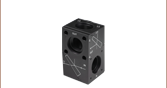
Zoom- 5.0 MP CMOS Camera-Based Analysis of Complex Beam Profiles
- Each Profiler Includes Six ND Filters on a Wheel
- Combine with Extension Sets Below to Build Complete M2 Measurement Systems
- Physical Dimensions (Including Filter Wheel): 94.3 mm x 84.8 mm x 85.7 mm (3.71'' x 3.34'' x 3.37'')
The BC207UV(/M) and BC207VIS(/M) CMOS camera beam profilers are designed for beam analysis over the 245 - 400 nm or 350 - 1100 nm wavelength range, respectively. Each includes a front-mounted filter wheel with six ND filters (see the ND Filters tab more details) to attenuate the beam and a 5.0 MP CMOS camera to image the beam profile in two dimensions. Each profiler has two 1/4"-20 (M6 x 1.0 mm) taps on the bottom for post mounting; one of these holes, located closest to the measurement plane, can also be used to attach the beam profiler to an M2 extension set (available below).
A USB 3.0 A to micro B cable (3.0 m length), filter cap, and quick-start guide are shipped with each beam profiler.

 Zoom
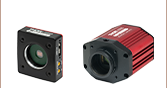
Zoom- 12.3 MP CMOS Camera-Based Analysis of Complex Beam Profiles
- Each Profiler Includes Six ND Filters on a Wheel
- Low-Profile Housing to Fit Into Space-Constrained Optical Setups
- Physical Dimensions (Including Filter Wheel): 95.8 mm x 88.4 mm x 34.7 mm (3.77'' x 3.48'' x 1.37'')
- Combine with Extension Sets Below to Build Complete M2 Measurement Systems
The BC210CU(/M) and BC210CV(/M) CMOS camera beam profilers have a compact housing designed for beam analysis over the 245 - 400 nm or 350 - 1100 nm wavelength range, respectively. Each profiler includes a front-mounted filter wheel with six ND filters (see the ND Filters tab for more details) to attenuate the beam, and a 12.3 MP CMOS camera to image the beam profile in two dimensions. Each profiler has two 1/4"-20 (M6 x 1.0 mm) taps on the bottom for post mounting or attachment to an M2MS series M2 measurement system (available separately below). There is an additional 1/4"-20 (M6 x 1.0 mm) tap on the bottom for post mounting only.
A USB 3.0 A to right-angle micro B cable (3.0 m length), filter cap, and quick-start guide are shipped with each beam profiler.

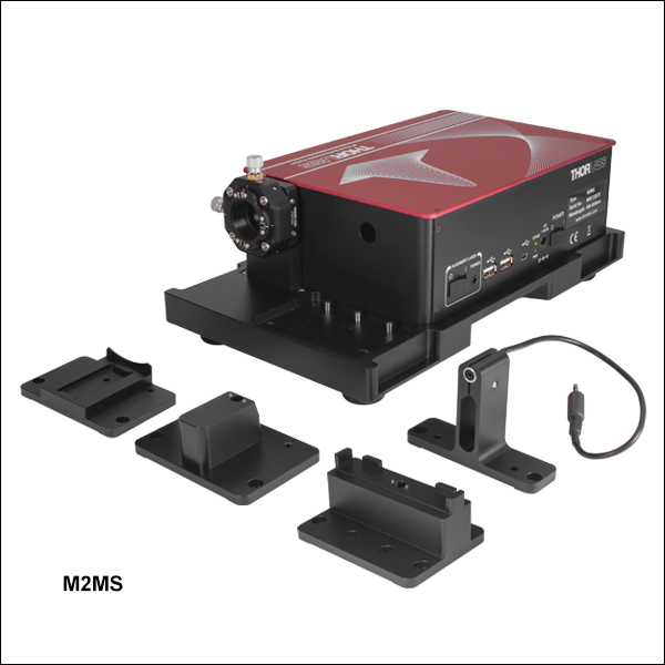 Zoom
Zoom| Item # | M2MS-AL | M2MS | |
|---|---|---|---|
| Wavelength Range | 250 - 600 nma | 400 - 2700 nma | |
| Beam Profiler Compatibilityb | BC207UV(/M)b BP209-VIS(/M) BC210CU(/M)b |
BC207VIS(/M)c BP209-VIS(/M) BP209IR1(/M) BP209-IR2(/M) BC210CV(/M)c |
|
| Internal Translation Stage |
Travel Range | 100 mm | |
| Velocity (Max) | 500 mm/s | ||
| Effective Translation Range | 200 mm (Total) ±100 mm (from Focal Point) |
||
| Lens Focal Length | 250 mm | ||
| Optical Axis Height | 70 mm (Without Additional Feet) |
||
| M² Measurement Range | >1.0 (No Upper Limit) | ||
| Typical M² Accuracy | ±5% (Depends on Optics and Alignment) |
||
| Minimum Detectable Divergence Angle |
<0.1 mrad | ||
| Applicable Light Sources | CW, Pulseda | ||
| Typical Measurement Time | 15 - 30 s |
||
| General Specifications | |||
| Size | 300 mm x 175 mm x 109 mm (Without Beam Profiler) |
||
| Weight | 4.2 kg (Without Beam Profiler) |
||
- Combine with BC207 Series or BC210C Series CMOS Camera Beam Profilers to Build a Complete M2 Measurement System
- Mirrors for the 250 - 600 nm or 400 - 2700 nm Range
- Mounting Adapters for BC207 and BC210C* Series Camera Beam Profilers and BP209 Scanning Slit Beam Profilers
- Includes an Alignment Laser
These extension sets are designed to convert Thorlabs' Camera or Scanning Slit Beam Profilers into a fully automated, motorized M² measurement system. The
The beam profiler and focusing lens remain in a fixed position. For M2 measurements, the beam path length is varied using a movable retroreflector mounted on a translation stage, which has a translation range of 100 mm and a maximum velocity of 500 mm/s.
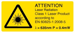 Each extension kit ships with a Class 1 alignment laser.
The side of the M² measurement system features an integrated USB 2.0 hub, which has ports for the slit beam profiler, one other device such as the TSP01 USB temperature and humidity controller, and a mini USB output connection to a PC. The translation stage inside of the system also communicates with the computer through this hub. As the BC207 and BC210C series beam profilers use USB 3.0 ports, they should be connected directly to a PC using their included USB 3.0 cables when used with the M2MS(-AL) system. The M2 measurement system extension set is controlled via the Thorlabs Beam software package which is also used to control our beam profilers (see the Software tab) and enables accurate measurements of a variety of beam-related parameters.
The housing of the M2 measurement extension set rests on four feet at the corners created by a 0.5 mm deep relief cut in the base. A set of RDF1 rubber damping feet are included. Five M6 x 1.0 mm taps allow for the installion of four damping feet with one near each corner or in a configuration using three damping feet.
More information about these complete M² measurement systems, as well information about M2 measurement systems that incorporate our scanning slit beam profilers can be found here.
*Users who purchased an M2 measurement system extension set before August 8, 2023 and wish to use a BC210C Series Camera Beam Profiler may receive the appropriate adapter by contacting Tech Sales.
Lenses Included with M2MS-AL*
Lenses with f = 250 mm Mounted in CXY1QF Quick Release Plate:
*Additional lenses for shorter UV wavelengths and the CXY1QF quick release front plate are available separately to enable further customization of the M2 measurement system.
Lenses Included with M2MS*
Lenses with f = 250 mm Mounted in CXY1QF Quick Release Plate:
- LA1461-A (AR Coated for 350 - 700 nm)
- LA1461-B (AR Coated for 650 - 1050 nm)
- LA1461-C (AR Coated for 1050 - 1700 nm)
- LA5255-D (AR Coated for 1650 - 3000 nm)
*Additional lenses for longer IR wavelengths and the CXY1QF quick release front plate are available separately to enable further customization of the M2 measurement system.
Accessories Included with M2MS-AL and M2MS
- Alignment Laser
- USB 2.0 to Mini B Cable, 3 m
- USB 2.0 to Mini B (Angled), 0.5 m)
- 15 V, 3.0 A Power Supply
- Adapters for BC207, BC210C, and BP209 Profilers
- 0.05" Hex Key
- 3 mm Balldriver
- Four CL6 Rail Clamps
- Six M4 x 0.7 mm Cap Screws