 Products Home / Optomechanical Components / Optomechanical Mounts / Optical Mirror Mounts / Kinematic/Gimbal Mount Accessories
Kinematic/Gimbal Mount Accessories
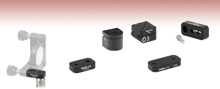
- Allow Greater Mount Versatility in Optical Setups
- Flip Mount Rotates a Mirror Mount 90 Degrees
- Adjustable Flip Platform Provides Continuous Angular Adjustment
- Centering Plates Align Mirror Mounts Over Post Axis
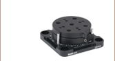
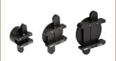
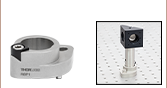
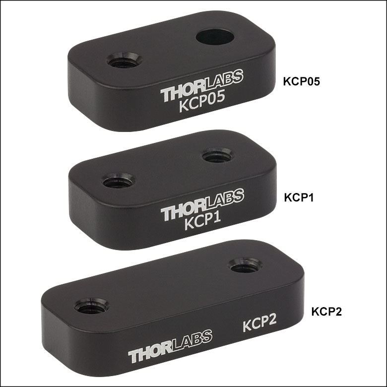
KCP1
Aligning the
Optical Face of
the Mirror in the
KM100 to the
Center of
the Post
KCP05
Fixed Centering Plate
for KM05 Mirror Mount
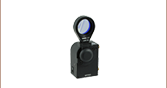
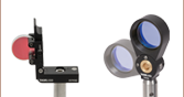
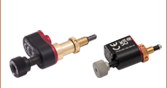
FM90
KCP2
Fixed Centering Plate
for KM200 Mirror Mount
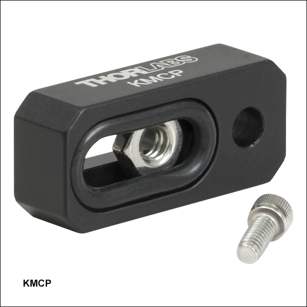
KMCP
FP90


Please Wait
Features
- Flip Mount Adapter and Adjustable Flip Platform Reposition Optic Mounts Out of a Beam Path
- Fixed Centering Plates Align the Front Face of an Optic Held in a Standard KM05(/M), KM100, or KM200 Kinematic Mount Over the Post Axis
- Variable Centering Plate Aligns the Front Face of an Optic Held in a KM-Series Mount or KS1 Precision Mount Over the Post Axis
- Fabricated from Black Anodized Aluminum
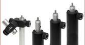
These kinematic/gimbal mount accessories are ideal for adding flexibility to an optical setup. The FM90(/M) Flip Mount Adapter is offered for repositioning an optical mount at 90° from its original position. The FP90(/M) Adjustable Flip Platform features a similar design, but with an array of 8-32 (M4) tapped holes for mounting a variety of components. The fixed centering adapters are designed to align the front face of an optic held in our KM05(/M), KM100, or KM200 Kinematic Mount over the center of a Ø1/2" or Ø1" post. Thorlabs also offers a variable centering plate for translating a kinematic mount between 0.46" (11.7 mm) and 0.79" (20.1 mm) from the center of the #8 (M4) counterbored hole used to post mount the plate.
| Posted Comments: | |
M Whit
(posted 2025-04-10 13:52:29.29) When using the flip mount adapter, the mirror is facing up when it is flipped down. The mirror is exposed to damage as well as building up dust and debris. It would be preferable to flip the mirror forward or to the side to protect the mirror, but this leaves the kinematic adjusters in the beam path. Is there some way to modify to allow the mirror to flip into a protected position? jdelia
(posted 2025-04-15 02:23:24.0) Thank you for contacting Thorlabs. The best way to do this would be to have the mirror flipped 180 degrees with respect to the flip mount adapter. However, as you mentioned, this would involve the adjusters being in the beam path. I have reached out to you directly to clarify your inquiry and discuss your application further. user
(posted 2018-11-08 23:30:36.083) May I suggest you consider the equivalent of the KCP05(/M) with 2 counterbores (or an equivalent design, maybe thinner)? This would allow to mount / interface 2 parts having both threaded holes and be able to align them (and this would answer my question regarding mounting the XYFM1 (target holder) on the DT12 (mini translation stage), asked on the DT12 feedback page). And there's a minor typo on the present page: "the centering plate [KCP2(/M)] for use with this mount provides one 8-32 (M4) tap and one #8 counterbore": it should be the KCP05(/M). llamb
(posted 2018-11-09 01:59:50.0) Thank you for your feedback! I have added this suggestion to our internal product forum for further discussion. I have also contacted our marketing team to update the typo accordingly. oba2002
(posted 2018-05-31 19:23:33.517) I have multiple mirror systems mounted on KM100 with FM90. I can select one mirror at a time by flipping the other mirrors down. How can I achieve this in a 30 mm cage system? YLohia
(posted 2018-06-01 08:40:44.0) Hello, there are a few options you can look into for a similar application within the 30mm cage system: CP360R (Pivoting, Quick-Release, Ø1" Optic Mount), CFH2 (30 mm Cage System Removable Filter Holder for Ø1" Optics), and CP09 (30 mm Removable Segment Cage Plate). blanc
(posted 2014-03-25 12:32:34.457) Dear Madam or sir,
Do you know if the KCP05/M is compatible with the KM05FL/M or the FR
Thanks in advance
Best regards
Olivier Blanc cdaly
(posted 2014-03-25 11:39:28.0) Response from Chris at Thorlabs: The KM05FL/M in the nominal position seats the face of the optic off of the mounting hole 11.5mm. The KCP05/M would work best for a mount which does this at 13.3mm, which is what the KM05/M with a 6mm thick optic does. I'd recommend using the KMCP/M which can have a varied offset anywhere between 9-20mm if you are looking to have the optic face right over the center of post. |

 Zoom
Zoom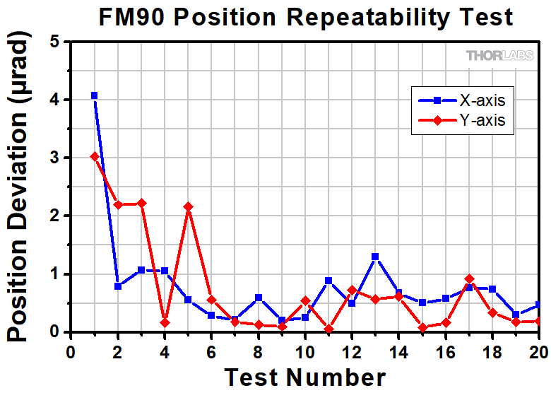
Click to Enlarge
Figure G1.2 Position Repeatability of the FM90 Flip Mount Adapter Over 20 Trials

Click to Enlarge
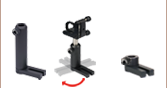
Figure G1.1 The FM90(/M) can be used to move a mounted mirror down out of a beam path (a) and back into the path (b).
- Rotates 90° to Clear Beam Path
- Kinematic Design Ensures Repeatability
- Mounting Options on Top Surface:
- Three 8-32 (M4) Mounting Holes
- One #8 (M4) Counterbore
- Post Mountable via 1/4" (M6) Counterbore
The FM90 is ideal for applications that require laser beams to be redirected for either diagnostic or beam sharing purposes. The hinged design allows an optical mount to be repositioned outside the beam path, and, when required, a simple flip of the adapter into its closed position (as shown in Figure G1.1) relocates the mount back into the beam path.
As shown in Figure G1.2, this can be accomplished with a repeatability of 4 µrad in each axis. In these tests a beam was redirected into a position detector using an FM90 Flip Mount and a KM100 Mirror Mount. The X-axis deviation, resulting from the tilt of the assembly, and the Y-axis deviation, resulting from the tip of the assembly, were each recorded over 20 tests.
The top surface of the adapter is equipped with three 8-32 (M4) tapped holes as well as one #8 counterbored hole for inserting a cap screw from the underside of the adapter. The base of the adapter is counterbored for a 1/4" (M6) cap screw to attach the adapter to a post or an optical table.
| 90° Flip Mounts Selection Guide | ||
|---|---|---|
| Post-Mounting Flip Mount Adapter | Optic Flip Mounts | Motorized Optic Flip Mounts |

 Zoom
Zoom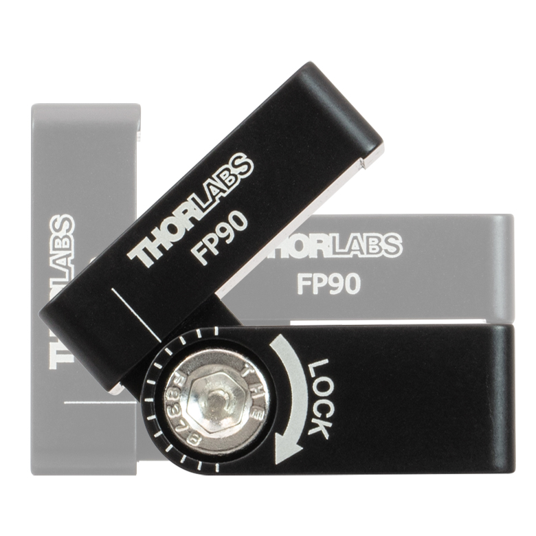
Click to Enlarge
Figure 625A The adjustable flip platform can be set to a user-defined angle for components with specific mounting requirements. The engraved scale with 15° increments guides platform angle positioning.
- Designed for 90° Angular Adjustment
- Up to 180° Adjustment Range in Certain Configurations
- Side-Located Locking Cap Screw with 3/16" (5 mm) Hex
- 1.25" x 1.25" Mounting Platform with Eleven 8-32 (M4) Tapped Holes
- 8-32 (M4) Mounting Tap on the Side of Each Plate
- Four 8-32 Tapped Holes on the Bottom Plate for Additional Mounting Options
- Engraved Tick Marks in 15° Increments
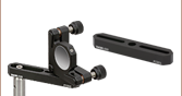
The Adjustable Flip Platform is designed to attach to the top of our Ø1/2" or Ø1" posts and provide flexible mounting options for components. The flip platform can be secured on the post using the #8 (M4) counterbore located in the center of the bottom plate, or the 8-32 (M4) tapped mounting hole on the side of each of the two plates. The 1.25" x 1.25" top plate features eleven 8-32 (M4) tapped holes for mounting components.
The angle of the top plate can be adjusted between 0° and 90° with respect to the optical table surface when mounted using the counterbore in the center of the bottom plate. When mounted using the 8-32 tapped hole on the side, the top plate can be adjusted between -90° and +90° with respect to the optical table surface. In order to lock the platform in place, tighten the cap screw on the side using a 3/16" (5 mm) balldriver or hex key.
The flip platform can be converted between a right- and left-handed setup. Simply remove the locking screw, separate the top and bottom plates, flip the bottom plate upside-down, and reassemble the flip platform. This allows the user to choose the direction from which the locking screw is accessed, in case one orientation better suits the experimental setup.
Click here for test data on the effectiveness of the flexure locking screw.
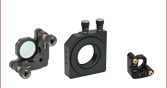
Thorlabs offers additional products that can be used to place a mirror or other optical component at a fixed angle such as the post mounting angle blocks.

 Zoom
Zoom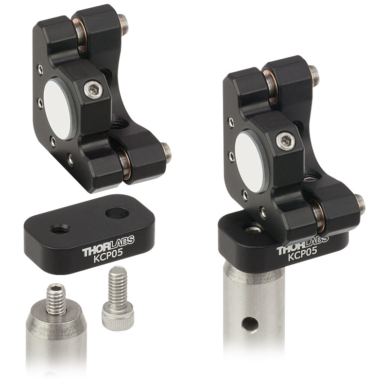
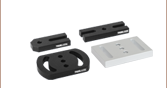
- Centers Mirror Face Over Post Rotation Axis for KM05(/M), KM100, or KM200 Standard Kinematic Mount
- Constructed from a Single Piece of Black Anodized Aluminum
As most conventional mirror mounts utilize their back plates for mounting to a post, the front surface of the optic is typically offset from the center of the mounting post. These centering plates are designed to position the front face of an optic in the KM05(/M), KM100, or KM200 Kinematic Mount over the center of a Ø1/2" or Ø1" post. Centering the optical face reduces any off-axis shift of the optical path when rotating the mounting post.
The KCP1(/M) and KCP2(/M) are equipped with two 8-32 (M4) taps. Thread a Ø1/2" post into one end, and secure the kinematic mount to the centering plate using the other tap. Since our kinematic mounts for Ø1/2" optics are designed with an 8-32 (M4) tap instead of a #8 counterbore like their Ø1" and Ø2" counterparts, the centering plate [KCP05(/M)] for use with this mount provides one 8-32 (M4) tap and one #8 counterbore (see Figure G3.1).
| Item # | Mounting | Compatible Kinematic Mount |
Optic Thickness Needed for Centering |
Total Length of Centering Plate |
Thickness of Centering Plate |
|---|---|---|---|---|---|
| KCP05(/M) | One 8-32 (M4) Tapped Hole, One #8 Counterbored Hole |
KM05 or KM05/M |
6 mm (0.24") | 1.02" (25.9 mm) | 0.25" (6.35 mm) |
| KCP1(/M) | 8-32 (M4) Tapped Holes, 2 Places |
KM100 | |||
| KCP2(/M) | 8-32 (M4) Tapped Holes, 2 Places |
KM200 | 12 mm (0.47") | 1.34" (34.0 mm) |

 Zoom
Zoom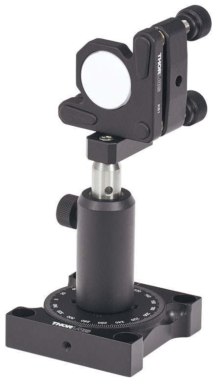
- Positions Optical Face in Line with Post Rotation Axis
- 8-32 (M4) Nut Attaches Kinematic Mounts
- Positioning Range of 0.33" (8.4 mm)
As most conventional mirror mounts utilize their back plates for mounting to a post, the front surface of the optic is typically offset from the center of the mounting post. The KMCP Centering Plate utilizes an 8-32 (M4) nut embedded within a slotted counterbore to attach a kinematic mirror mount. The center of the nut translates between 0.46" (11.7 mm) and 0.79" (20.1 mm) from the center of the counterbored #8 (M4) hole used to post mount the centering plate. The mirror's front surface can be positioned over a range of 0.33" (8.4 mm), allowing the front surface of the mirror to be centered over the Ø1/2" mounting post. This reduces any off-axis shift of the optical path when rotating the mounting post. The KMCP can alternatively be used as an extension to insert a mount into a beam path when space limitations prevent using a post holder.
This centering plate is compatible with any KM-series mounts, the KS1 Precision Kinematic Mount, and all Ø1/2" Posts.
Video G4.2 Use an 8-32 (M4) cap screw to attach the mount to the KMCP using the sliding nut. The counterbored #8 (M4) through hole on the KMCP is then used to attach the KMCP to a post.
Video G4.3 Use an 8-32 (M4) cap screw to attach the mount to the KMCP using the counterbored #8 (M4) through hole on the KMCP. The sliding nut is then used to attach the KMCP to a post.