 Products Home / Optical Elements / Optical Filters / Neutral Density Filters / Variable ND Filters / Variable Absorptive Neutral Density Filter
Variable Absorptive Neutral Density Filter

- Neutral Density Filter with OD from 0.8 to 3.0
- Attenuates Visible Light
- Post Mountable and 30 mm Cage Compatible
NEV0830M
Variable Absorptive Neutral Density Filter
Application Idea
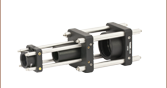
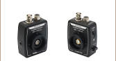
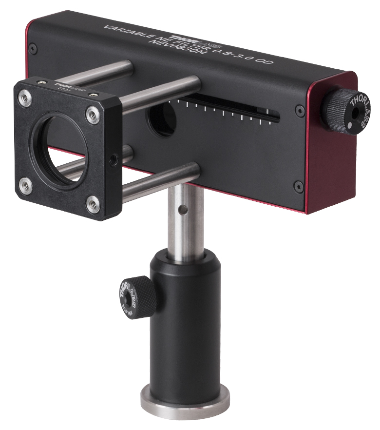
NEV0830M on a Ø1/2" Post with a CP33 30 mm Cage Plate


Please Wait
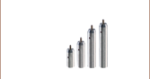
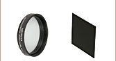
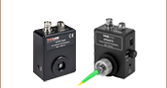
| Variable ND Selection Guide | ||||||
|---|---|---|---|---|---|---|
| Image |  |
 |
 |
 |
 |
 |
| ND Filter Type |
Round Step | Round Continuous |
Cage Compatible |
Rectangular Step |
Rectangular Continuous |
Variable Absorptive ND Filter |
Click to Enlarge
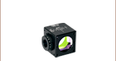
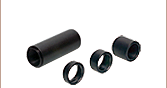
Figure 1.1 The Variable Absorptive Neutral Density Filter can be mounted on a post via the bottom-located 8-32 tap. Four 4-40 taps on both the front and back of the housing allow the filter to be integrated into a 30 mm cage system.

Click to Enlarge
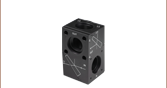
Figure 1.2 Beam Path Through Variable Absorptive ND Filter
Features
- Variable Optical Density Between 0.8 and 3.0
- Ø8.5 mm Maximum Input Beam Size
- 8-32 Tap for Post Mounting
- Compatible with 30 mm Cage Systems
- SM05-Threaded Aperture on Both Sides of Housing
- NG5 (Schott Glass) Substrate
- Ideal for Low-Power Applications
Thorlabs' Variable Absorptive Neutral Density Filter can provide an optical density (OD) between 0.8 and 3.0. The filter consists of two NG5 Schott Glass prisms which can be translated using the adjuster knob on the side of the housing. Varying the position of the prisms with respect to one another varies the amount of the substrate through which the beam travels, thereby changing the effective OD of the filter. See Figure 1.2 for an illustration of the beam path. Unlike our Variable Beamsplitter/Attenuators, this filter does not induce polarization effects on the beam.
Rotating the adjustment knob clockwise yields a larger OD; the prism position indicator (located on the front of the housing) moves to the right as the OD increases. Each tick mark on the indicator is equivalent to a 0.2 change in OD.
The filter has a clear aperture of Ø10 mm. However, because the beam will be displaced horizontally by 1.5 mm, the input light beam should be Ø8.5 mm or smaller. When the beam enters through the front of the filter, the beam will be displaced to the left.
The anodized aluminum housing is 4.97" x 1.03" x 1.76", not including the adjustment knob. It can be mounted on a Ø1/2" post using the
Optical Density
Optical density (OD) indicates the attenuation factor provided by an optical filter, i.e. how much it reduces the optical power of an incident beam. OD is related to the transmission, T, by the equation
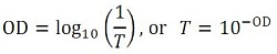
where T is a value between 0 and 1. Choosing an ND filter with a higher optical density will translate to lower transmission and greater absorption of the incident light. For higher transmission and less absorption, a lower optical density would be appropriate. As an example, if a filter with an OD of 2 results in a transmission value of 0.01, this means the filter attenuates the beam to 1% of the incident power. Please note that the transmission data for our neutral density filters is provided in percent (%).
Please note that this product is not designed for use as laser safety equipment. For lab safety, Thorlabs offers an extensive line of safety and blackout products, including beam blocks, that significantly reduce exposure to stray light.
| Specifications | |
|---|---|
| Optical Density | Variable Between 0.8 and 3.0 |
| Wavelength Range | 400 - 650 nm |
| Clear Aperture | Ø10 mma |
| Maximum Input Beam Size | Ø8.5 mm |
| Beam Displacement | 1.5 mm (Max) |
| Prism Substrate | NG5 (Schott Glass) |
| Surface Quality | 40-20 Scratch-Dig |
| Housing Dimensions (W x D x H) |
4.97" x 1.03" x 1.76" (126.2 mm x 26.3 mm x 44.7 mm) |
| Aperture Threading | SM05 (0.535"-40) |
| Mounting Hole | 8-32b |
Click to Enlarge
Figure 2.1 This plot shows the transmission of NG5 Schott Glass over a range of wavelengths for select optical densities. Click here for the raw transmission data for
| Posted Comments: | |
Stefanie M
(posted 2023-01-16 13:36:13.75) Dear Thorlabs team, what is the Damage Threshold of this filter? cdolbashian
(posted 2023-01-23 03:05:42.0) Thank you for reaching out to us with this inquiry. We unfortunately have not tested this device for general damage thresholds. I have contacted you directly to inquire about your specific optical source so that we might be able to validate your particular laser. christopher.wade
(posted 2018-01-22 17:45:38.52) Hi - Is there a motorised version of NEV0830M that could be automated? Thanks. Chris nbayconich
(posted 2018-03-29 11:50:17.0) Thank you for contacting Thorlabs. At the moment we do not have a motorized version of the NEV0830 variable ND filter system, I will forward your feedback for future consideration in our product line. If a continuous change in optical density is not required we do have automated filter wheels such as the FW series. knoechel
(posted 2016-05-19 03:37:20.33) As far as I can understand the setup of the NEV0830M, beam displacement will change when changing the distance between the two prism. Is that correct? besembeson
(posted 2016-05-19 09:10:08.0) Response from Bweh at Thorlabs USA: Yes that is correct. It will change up to a maximum of 1.5mm displacement. |