 Products Home / Motorized Stages / Pitch/Yaw Stages and Goniometers / Long-Travel Motorized Goniometers with Integrated Controller, Stepper Motor
Long-Travel Motorized Goniometers with Integrated Controller, Stepper Motor
- ±30° or ±50° Pure Rotational Motion About a Fixed Axis Above the Stage
- Closed-Loop Operation with Down to ±50 µrad Accuracy
- Integrated Stepper Motor and Controller
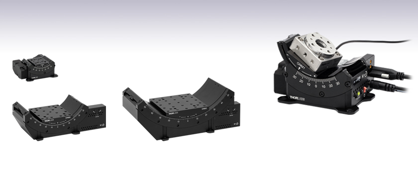
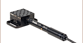
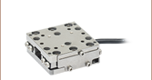
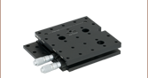
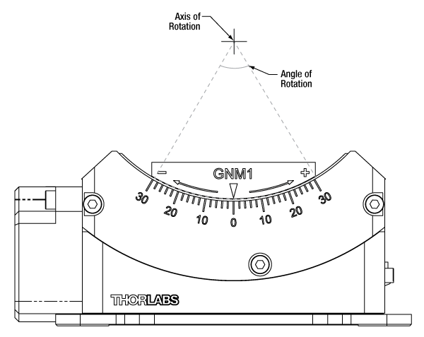
GNM1
Single-Axis Motorized Goniometer,
±30° Travel, 30 mm to Point of Rotation
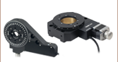
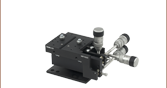
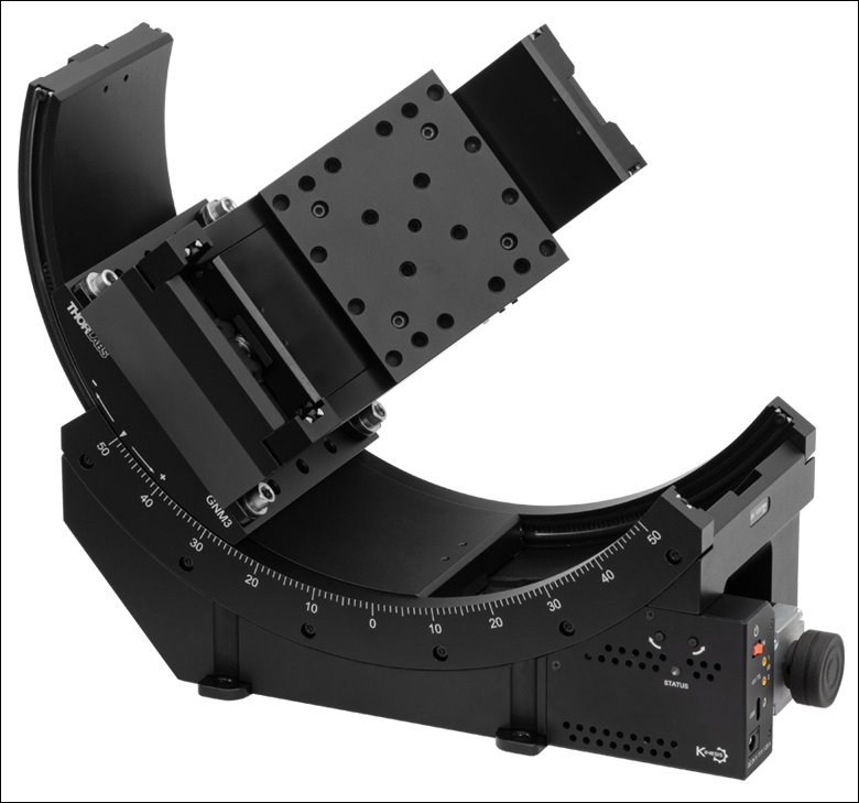
Application Idea
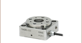
ORIC® PDR1 Rotation Stage Mounted on
GNM1 Stage Shown at -30° Position
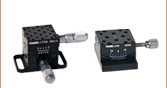
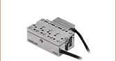
GNM2
Single-Axis Motorized Goniometer,
±50° Travel, 70 mm to Point of Rotation
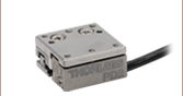
GNM3
Single-Axis Motorized Goniometer,
±50° Travel, 120 mm to Point of Rotation


Please Wait
Click for Details
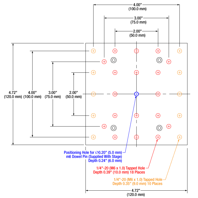
Figure 1.3 GNM3(/M) Moving World Mounting Options

Click for Details
Figure 1.2 GNM2(/M) Moving World Mounting Options
Click for Details
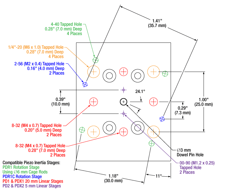
Figure 1.1 GNM1(/M) Moving World Mounting Options
Features
- Pure Rotational Motion About a Fixed Virtual Axis
- Integrated Stepper Motor & Controller
- Remote Control via Kinesis Software & Manual Control Using On-Unit Buttons
- 5 V TTL Input and Output Trigger Ports
- 2° Graduation Markings on Side
- Three Sizes Available with ±30° (Item # GNM1(/M)) or ±50° (Item #s GNM2(/M) and GNM3(/M)) Translation
- Manual and Motorized ±8°/±5° Goniometer Stages Also Available

Click to Enlarge
Figure 1.6 A GNM1 goniometric stage is mounted on the larger GNM2 stage which is mounted on the larger GNM3 stage; this configuration results in a common virtual pivot point between the three stages, providing pure spherical motion. Since the GNM1 stage is parallel to the GNM3 stage and they are separated by 50.0 mm vertically, they share a common axis of rotation and translation in this direction is extended to up to 80°.
Click to Enlarge
Figure 1.5 A GNM2 goniometric stage is mounted on the larger GNM3 stage, resulting in a common pivot point between the two stages and providing pure spherical motion up to 50° in any direction.
The GNMx(/M) series of motorized goniometers offer unobstructed, pure rotational motion about their virtual axes of rotation. They each feature an integrated microstepping motor, optical encoder, and controller designed for remote operation, as well as jog buttons on the side for manual actuation. Input and output triggers enable external triggering using 5 V TTL signals.
The GNM1(/M) goniometer rotates its 40.0 mm x 50.0 mm (1.57" x 1.97") moving platform over a ±30° range, 30 mm above the moving platform surface (see Figure 1.4). The GNM2(/M) and GNM3(/M) goniometers rotate their 86.0 mm x 94.0 mm (3.39" x 3.70") or 120.0 mm x 120.0 mm (4.72" x 4.72") moving platforms, respectively, over a ±50° range, with axis of rotation 70 mm or 120 mm above their moving platform surfaces (see Figure 1.4).
These goniometers are designed to stack while maintaining a common virtual axis of rotation or pivot point. Because the distance from the center of the top mounting surface to the rotation axis on the larger stages matches the distance from the bottom surface to the axis on the next smaller stage, they can be combined to extend travel or enable spherical translation in a perpendicular direction. For example, stacking a GNM2 medium stage on a GNM3 large stage and a GNM1 small stage on the GNM2 medium stage as shown in Figure 1.6 results in up to 80° of travel in one direction and 50° of travel in the perpendicular spherical coordinate.
Click to Enlarge
Figure 1.4 Representative Motorized Goniometer Diagram
These stages are compatible with our Kinesis software package, which can be downloaded here. Please see the Kinesis Software tab for more information. A CABCUL72 locking USB Type-C cable is included for remote connections, as well as two CA3272 MMCX-to-BNC input and output trigger cables, and a KPS201 15 VDC power supply (Item # GNM1(/M)) or 24 VDC power supply (Item #s GNM2(/M) and GNM3(/M)). CA3439 MMCX-to-SMA cables are available separately.
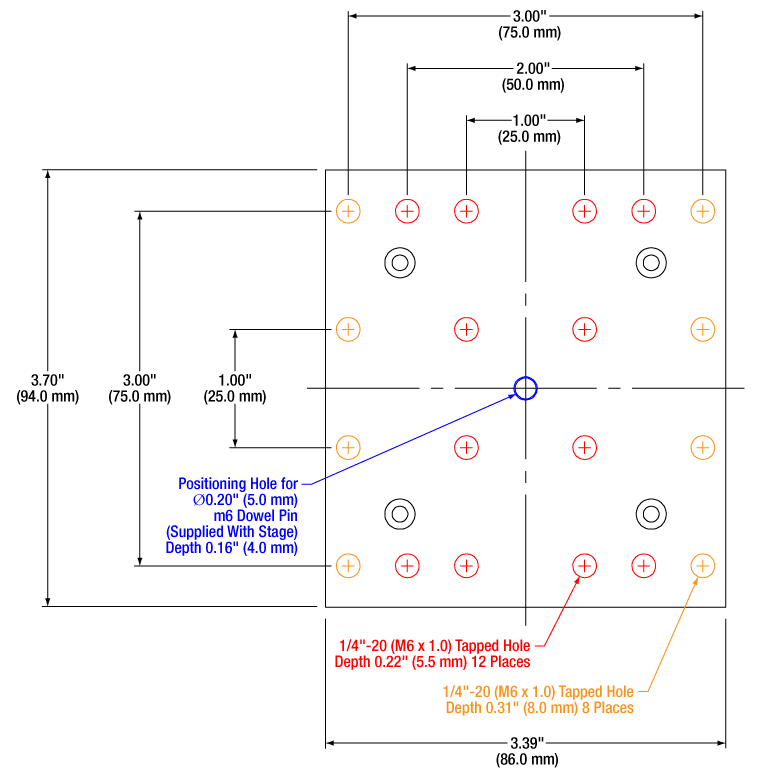
The GNM1(/M) stage provides an array of mounting holes for compatibility with ORIC piezo inertia rotation and translation (5 mm and 20 mm) stages as well as general optomech, while the larger GNM2(/M) and GNM3(/M) stages provide arrays of 1/4"-20 (M6 x 1.0) mounting holes for mounting general optomechancial components and many of our other stages; click Figures 1.1, 1.2, and 1.3 for details. The base of each stage features either three or four 1/4" (M6) mounting bores that are compatible with imperial or metric hole patterns. Dowel pin holes on the moving platform and base of each stage enable precise positioning using the included dowel pins.
An individualized test report is included with each stage to provide an overview of measured performance; click here for a sample report. Testing data can be obtained using the serial number on the stage via the product page links below.
| Item # | GNM1(/M) | GNM2(/M) | GNM3(/M) |
|---|---|---|---|
| Stage Specifications | |||
| Distance from Top Surface to Axis of Rotation (H) |
30.00 mm ± 0.01 mm (1.18" ± 0.0004") |
70.00 mm ± 0.01 mm (2.76" ± 0.0004") |
120.00 mm ± 0.01 mm (4.72" ± 0.0004") |
| Distance from Bottom Surface to Axis of Rotation |
70.00 mm ± 0.01 mm (2.76" ± 0.0004") |
120.00 mm ± 0.01 mm (4.72" ± 0.0004") |
190.00 mm ± 0.01 mm (7.48" ± 0.0004") |
| Platform Size | 40.0 mm x 50.0 mm (1.57" x 1.97") |
86.0 mm x 94.0 mm (3.39" x 3.70") |
120.0 mm x 120.0 mm (4.72" x 4.72") |
| Centered Load Capacity (P) | 20 N / 2.03 kg (4.47 lbs) | 60 N / 6.10 kg (13.45 lbs) | 200 N / 20.40 kg (44.97 lbs) |
| Off-Center Load (Q) | ≤ 20 / (1 + D/40) N (D = Cantilever Dist. in mm) |
≤ 60 / (1 + D/40) N (D = Cantilever Dist. in mm) |
≤ 200 / (1 + D/40) N (D = Cantilever Dist. in mm) |
| Max Torque (My) | 0.5 N•m | 1.18 N•m | 7.8 N•m |
| Travel | ±30° | ±50° | |
| Speed Range | 0.005 - 25 °/s | 0.001 - 50 °/s | |
| Max Acceleration (2 kg Load) | 25 °/s2 | 50 °/s2 | |
| Bidirectional Repeatability | ±50 µrad | ±25 µrad | |
| Home Location Repeatability | ±50 µrad | ±25 µrad | |
| Min Repeatable Incremental Movementa | 90 µrad | 50 µrad | |
| Position Angle Accuracy (A) | ±150 µrad | ±75 µrad | ±50 µrad |
| Yaw Angular Deviationb | 400 µrad | 300 µrad | 200 µrad |
| Roll Angular Deviationc | 400 µrad | 300 µrad | 200 µrad |
| Radius of Confusion (R)d | <40 µm Max | <60 µm Max | |
| Motor Specifications | |||
| Motor Type | Stepper with Microsteps | ||
| Motor Drive Voltage | ±15 V | ±24 V | |
| Max Motor Drive Current | <150 mA | <700 mA | <1 A |
| Motion Control Algorithm | Exponential Approach Algorithm | ||
| Quadrature Encoder Resolution | 0.1 µm | ||
| Velocity Profile | Trapezoidal | ||
| Voltage | 15 V Regulated DC | 24 V Regulated DC | |
| Current | 500 mA (Peak) | 1 A (Peak) | 1.25 A (Peak) |
| General Specifications | |||
| Dimensions (W x D x H) at Mid Travel |
97.0 mm x 82.4 mm x 42.7 mm (3.82" x 3.24" x 1.68") |
242.0 mm x 112.0 mm x 74.9 mm (9.53" x 4.50" x 2.95") |
299.0 mm x 137.0 mm x 110.3 mm (11.77" x 5.46" x 4.34") |
| Mass (Without Cables) | 0.45 kg (0.99 lbs) | 2.37 kg (5.22 lbs) | 5.70 kg (12.57 lbs) |
Specification Details
Centered Load Capacity
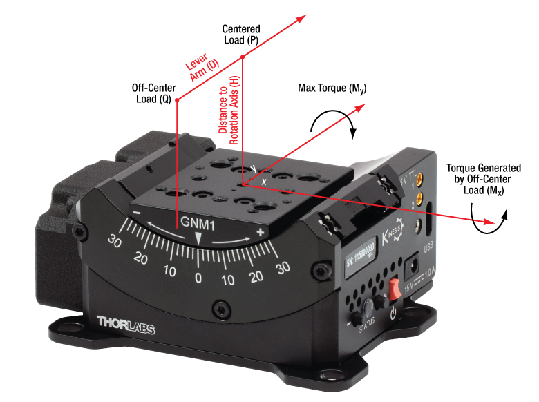
Click to Enlarge
Figure 2.1 Load Capacity Illustration
- Centered Load capacity is specified for a load with a center of mass located on the rotation axis and above the top plate's center (P).
- If the load is displaced along the rotation axis, then it generates Mx torque and should be decreased according to the formula: Q≤P/(1+D/k) (N). P is the max centered load capacity of the stage in N and D is the lever arm distance in mm. The coefficient “k” depends on a number of factors but is equal to 40 mm for each of the GNMx stages; for the GNM1 stage, the load should be less than 20/(1+D/40) Newtons.
- If the load is moved out of the rotation axis, it generates My torque, which is limited by the Max Torque parameter. My torque should not exceed Max Torque during the whole travel range.
Yaw & Roll Deviation
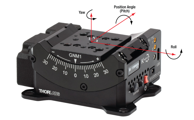
Click to Enlarge
Figure 2.2 Yaw & Roll Deviation Illustration

Click to Enlarge
Figure 2.3 Sample Yaw & Roll Deviation Measurements
- The Z axis is specified as the line through the center of the top plate that is perpendicular to the axis of rotation.
- Yaw is the rotation angle of the top plate around the Z axis, assuming the homing position is zero.
- Roll is the rotation angle of the top plate around the X axis, assuming the homing position is zero.
- The yaw and roll deviations are calculated as the difference between maximum and minimum values.
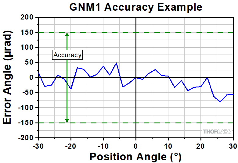
Accuracy
Click to Enlarge
Figure 2.4 Sample Accuracy Measurements
- Accuracy refers to a maximum positioning error.
- The position angle is calculated as the angle between the projections to the XZ plane of the normal vectors to the top plate surface in the current and homed positions.
Radius of Confusion
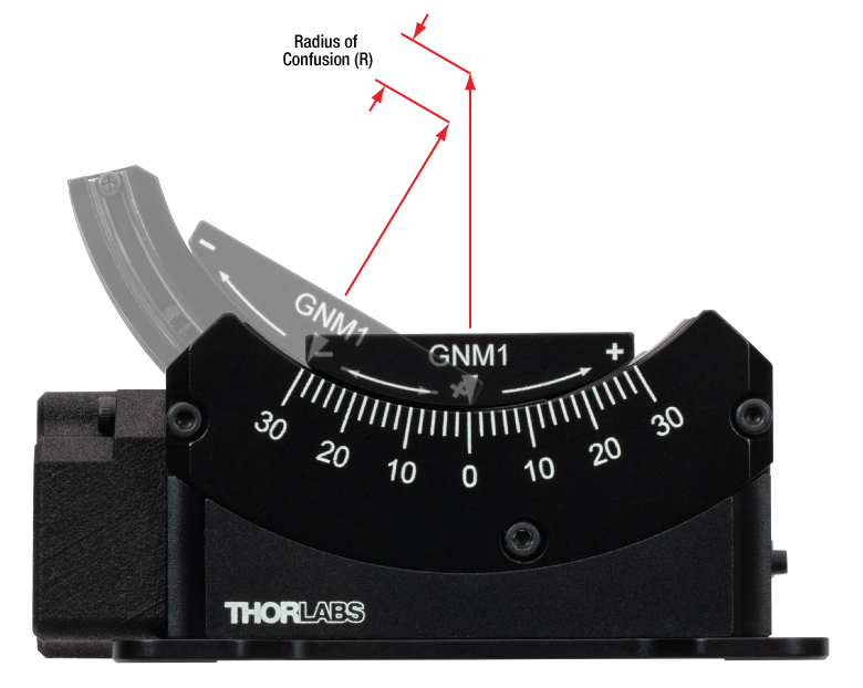
Click to Enlarge
Figure 2.5 Radius of Confusion Illustration
- Radius of confusion refers to the amount of deviation shown by a fixed point that is securely attached to the top plate and positioned along a rotational axis in a central homing position above the center of the top plate.
- It is calculated as the maximum distance between the calculated points during rotation and the one at the homed position.
Click to Enlarge
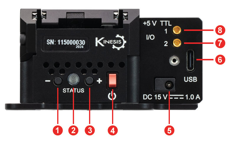
Figure 3.1 GNM1(/M) Side Panel
| Table 3.2 GNM1(/M) Side Panel | |
|---|---|
| Callout | Description |
| 1 | Reverse Jog Button |
| 2 | Status LED |
| 3 | Forward Jog Button |
| 4 | Power Switch |
| 5 | Power Supply Connector |
| 6 | USB Type-C Connectora |
| 7 | Input Connector, MMCX Socket, 5 V TTLb |
| 8 | Output Connector, MMCX Socket, 5 V TTLb |
Click to Enlarge
Figure 3.3 GNM2(/M) Side Panel

Click to Enlarge
Figure 3.4 GNM2(/M) Front Panel
| Table 3.5 GNM2(/M) Side Panel | |
|---|---|
| Callout | Description |
| 1 | Power Switch |
| 2 | Output Connector, MMCX Socket, 5 V TTLa |
| 3 | Input Connector, MMCX Socket, 5 V TTLa |
| 4 | USB Type-C Connectorb |
| 5 | Power Supply Connector |
| 6 | Knob for Manually Moving the Stagec |
| 7 | Reverse Jog Button |
| 8 | Forward Jog Button |
| 9 | Status LED |

Click to Enlarge
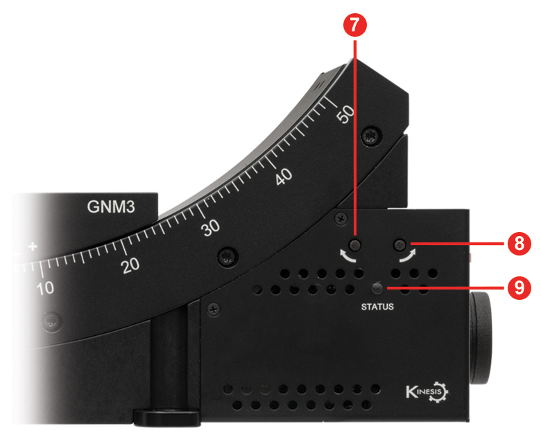
Figure 3.6 GNM3(/M) Side Panel
Click to Enlarge
Figure 3.7 GNM3(/M) Front Panel
| Table 3.8 GNM3(/M) Side Panel | |
|---|---|
| Callout | Description |
| 1 | Power Switch |
| 2 | Output Connector, MMCX Socket, 5 V TTLa |
| 3 | Input Connector, MMCX Socket, 5 V TTLa |
| 4 | USB Type-C Connectorb |
| 5 | Power Supply Connector |
| 6 | Knob for Manually Moving the Stagec |
| 7 | Reverse Jog Button |
| 8 | Forward Jog Button |
| 9 | Status LED |
Click to Enlarge
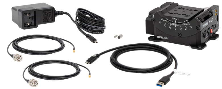
Figure 4.1 GNM1(/M) Stage Contents
GNM1(/M) Shipping List
- Goniometer Stage
- KPS201 Power Supply, 15 VDC, 2.4 A
- Two CA3272 MMCX Male to BNC Male Cables, 72" (1.8 m) Long
- CABCUL72 USB 3.0 Type-A to Type-C Cable with Locking Screw, 72" (1.8 m) Long
- Ø3 mm x 10 mm Dowel Pin, m6 Tolerance, Hardened Steel
- Ø5 mm x 10 mm Dowel Pin, m6 Tolerance, Hardened Steel
- Individualized Test Report
Click to Enlarge
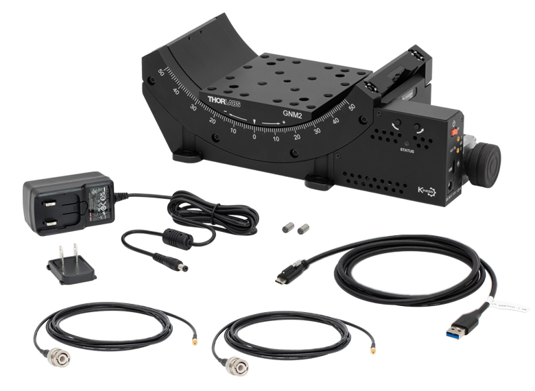
Figure 4.2 GNM2(/M) Stage Contents
GNM2(/M) Shipping List
- Goniometer Stage
- Power Supply, 24 VDC, 1.25 A
- Two CA3272 MMCX Male to BNC Male Cables, 72" (1.8 m) Long
- CABCUL72 USB 3.0 Type-A to Type-C Cable with Locking Screw, 72" (1.8 m) Long
- Two Ø5.0 mm x 10 mm Dowel Pins, m6 Tolerance, Hardened Steel
- Individualized Test Report
Click to Enlarge
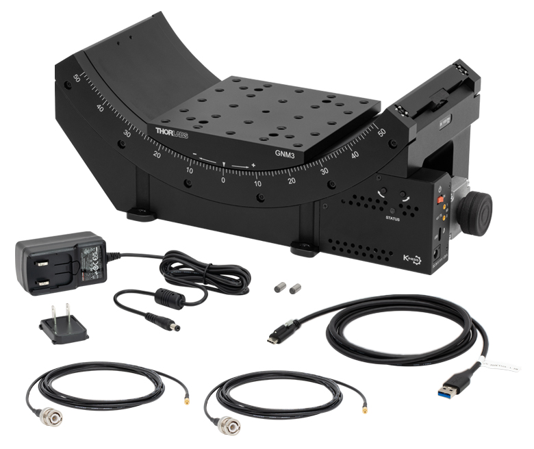
Figure 4.3 GNM3(/M) Stage Contents
GNM3(/M) Shipping List
Software
Kinesis Version 1.14.57
The Kinesis Software Package, which includes a GUI for control of Thorlabs' Kinesis system controllers.
Also Available:
- Firmware Update Utilities
- Communications Protocol
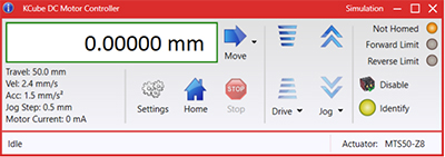
Figure 58A Kinesis GUI Screen
Thorlabs offers the Kinesis software package to drive our wide range of motion controllers. The software can be used to control devices in the Kinesis family, which covers a wide variety of motion controllers ranging from small, low-powered, single-channel drivers (such as the K-Cubes®) to high-power, multi-channel benchtop units and modular 19" rack nanopositioning systems (the MMR60x Rack System).
The Kinesis Software features .NET controls which can be used by 3rd party developers working in the latest C#, Visual Basic, LabVIEW™, or any .NET compatible languages to create custom applications. Low-level DLL libraries are included for applications not expected to use the .NET framework and APIs are included with each install. A Central Sequence Manager supports integration and synchronization of all Thorlabs motion control hardware.
By providing this common software platform, Thorlabs has ensured that users can mix and match any of our motion control devices in a single application, while only having to learn a single set of software tools. In this way, it is perfectly feasible to combine any of the controllers from single-axis to multi-axis systems and control all from a single, PC-based unified software interface.
The software package allows two methods of usage: graphical user interface (GUI) utilities for direct interaction with and control of the controllers 'out of the box', and a set of programming interfaces that allow custom-integrated positioning and alignment solutions to be easily programmed in the development language of choice.
Thorlabs' Kinesis software features new .NET controls which can be used by third-party developers working in the latest C#, Visual Basic, LabVIEW™, or any .NET compatible languages to create custom applications.
C#
This programming language is designed to allow multiple programming paradigms, or languages, to be used, thus allowing for complex problems to be solved in an easy or efficient manner. It encompasses typing, imperative, declarative, functional, generic, object-oriented, and component-oriented programming. By providing functionality with this common software platform, Thorlabs has ensured that users can easily mix and match any of the Kinesis controllers in a single application, while only having to learn a single set of software tools. In this way, it is perfectly feasible to combine any of the controllers from the low-powered, single-axis to the high-powered, multi-axis systems and control all from a single, PC-based unified software interface.
The Kinesis System Software allows two methods of usage: graphical user interface (GUI) utilities for direct interaction and control of the controllers 'out of the box', and a set of programming interfaces that allow custom-integrated positioning and alignment solutions to be easily programmed in the development language of choice.
For a collection of example projects that can be compiled and run to demonstrate the different ways in which developers can build on the Kinesis motion control libraries, click on the links below. Please note that a separate integrated development environment (IDE) (e.g., Microsoft Visual Studio) will be required to execute the Quick Start examples. The C# example projects can be executed using the included .NET controls in the Kinesis software package (see the Kinesis Software tab for details).
 |
Click Here for the Kinesis with C# Quick Start Guide Click Here for C# Example Projects Click Here for Quick Start Device Control Examples |
|
LabVIEW
LabVIEW can be used to communicate with any Kinesis-based controller via .NET controls. In LabVIEW, you build a user interface, known as a front panel, with a set of tools and objects and then add code using graphical representations of functions to control the front panel objects. The LabVIEW tutorial, provided below, provides some information on using the .NET controls to create control GUIs for Kinesis-driven devices within LabVIEW. It includes an overview with basic information about using controllers in LabVIEW and explains the setup procedure that needs to be completed before using a LabVIEW GUI to operate a device.
 |
Click Here to View the LabVIEW Guide Click Here to View the Kinesis with LabVIEW Overview Page |
|
| Posted Comments: | |
| No Comments Posted |
| Item # | Travel | Distance from Bottom Surface to Axis of Rotation |
Platform Size | Platform Mounting Optionsa | Centered Load Capacity | Speed Range |
|---|---|---|---|---|---|---|
| GNM1(/M) | ±30° | 70.0 mm (2.76") | 40.0 mm x 50.0 mm (1.57" x 1.97") |
 |
20 N / 2.03 kg (4.47 lbs) | 0.005 - 25 °/s |
| GNM2(/M) | ±50° | 120.0 mm (4.72") | 86.0 mm x 94.0 mm (3.39" x 3.70") |
 |
60 N / 6.10 kg (13.45 lbs) | 0.001 - 50 °/s |
| GNM3(/M) | 190.0 mm (7.48") | 120.0 mm x 120.0 mm (4.72" x 4.72") |
 |
200 N / 20.40 kg (44.97 lbs) |