 Products Home / Detectors / Amplified Detectors / Fast Thermal Sensor Amplified Detector for Pulsed Lasers
Fast Thermal Sensor Amplified Detector for Pulsed Lasers
- Wavelength Range from 190 nm to 2400 nm
- For Pulsed Lasers with Repetition Rates Up to 1 MHz
- Adjustable Gain Selection (36 dB Range)
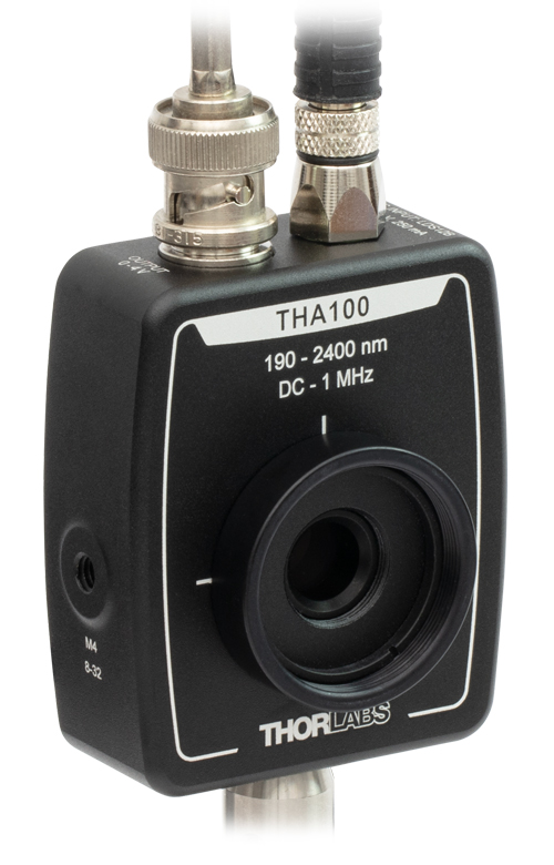
THA100
Switchable-Gain Fast
Thermal Sensor Amplified Detector
Side View
(8 Gain Steps)
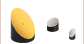
The MPD149-M01 Off-Axis Parabolic Mirror can be used to focus a collimated source in the NIR, making it ideal for use with the THA100 detector.


Please Wait
Click to Enlarge
Figure 1.2 Off-Axis Parabolic Mirrors can be used to focus a collimated source over a wide wavelength range, making them ideal for use with the THA100 detector.

Click to Enlarge
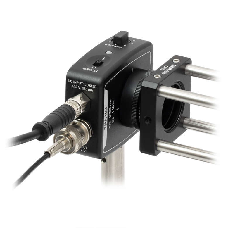
Figure 1.1 Each THA100 detector is shipped with an LDS12B power supply.
Features
- Wavelength Range: 190 - 2400 nm
- Amplification with Switchable Gain
- Optimized for High-Energy Pulsed or Chopped Light Sources
- 10 ns Typical Rise Time and 800 ns Typical Fall Time
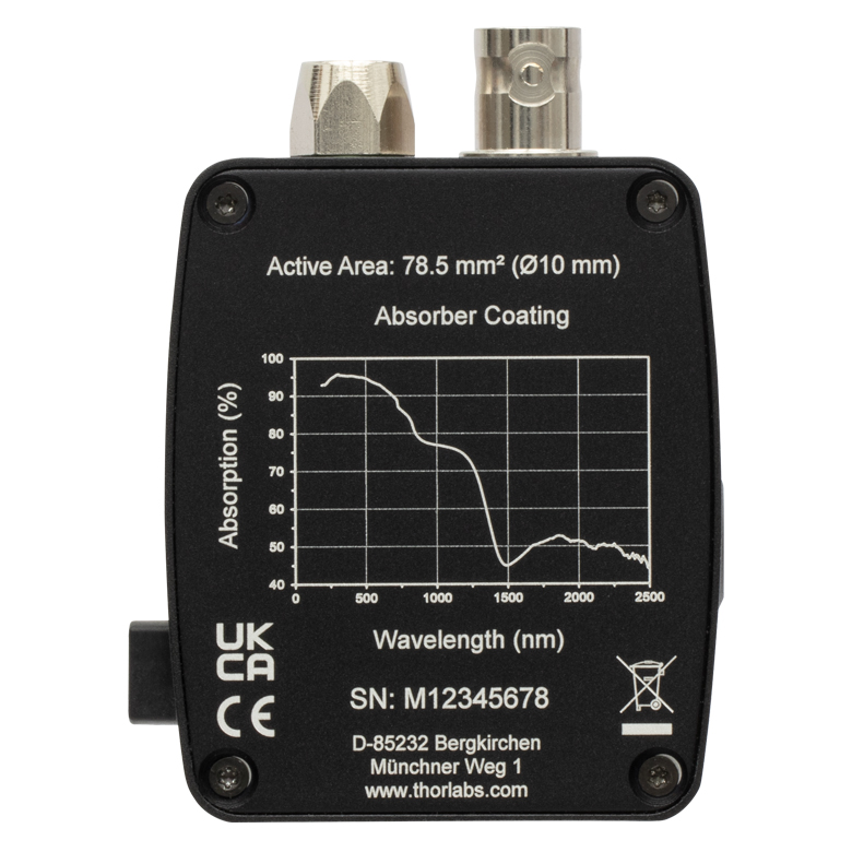
- Detector Active Area: 78.5 mm2 (Ø10 mm)
- External SM1 (1.035"-40) Threads and Internal SM05 (0.535"-40) Threads
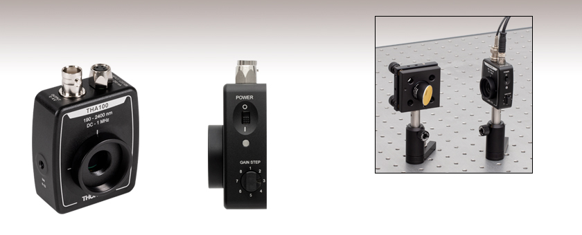
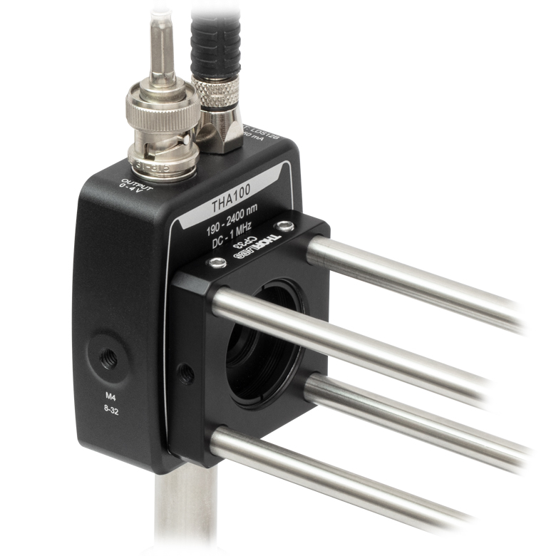
Thorlabs' THA100 Fast Thermal Sensor Amplified Detector is an amplified, switchable-gain, tetrathiotetracene (TTT) based detector for use with pulsed light signals between 190 nm and 2400 nm. While it is designed for short, high-energy laser pulses, it can also be used to measure modulated or pure continuous wave (CW) sources. A rotary switch on the side of the housing allows for the signal amplification to be adjusted in 8 gain steps up to 36 dB. The signal output is provided via a BNC connector and is capable of driving 50 Ω and high impedance loads with a maximum output voltage of 2 V and 4 V, respectively.
Click to Enlarge
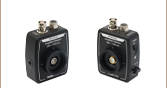
Figure 1.3 The back of the THA100 detector displays a sample absorption spectrum.
The outer surface of the THA100 sensor is a thin copper electrode coating which, in combination with the TTT layer below, efficiently absorbs incident photons. This sensor element is built upon submicron thermopile thick film technology whereby the heat flow generated by photon absorption passes perpendicularly through the material layers. The TTT material exhibits an intrinsic Seebeck effect which then converts this thermal energy into electrical energy, resulting in a typical signal rise time of 10 ns and a typical signal fall time of 800 ns. These response times, combined with high power handling and sensitivity, make the detector ideal for monitoring fast manufacturing processes and detecting instabilities in ultrashort laser pulses with repetition rates up to 1 MHz.
The detector's large active area (78.5 mm2) combined with its ability to handle high peak power densities up to 100 kW/cm2 makes it a great choice for measuring light sources with both broad intensity ranges and high peak pulse energies. At gain setting 1 (0 dB), the detector has a sensitivity of 1500 V/J for pulses shorter than 1 µs and 5 mV/W for CW and quasi-CW (QCW) input.
The THA100 detector has a broad absorption wavelength range, from 190 nm to 2400 nm, making it useful for applications with light from UV into MIR wavelengths. For quick reference, the absorption spectrum of the detector is printed on the back of the housing, as shown in Figure 1.3. For more information on the spectral response of the THA100 detector, please see the performance plots below or in the Specs tab.
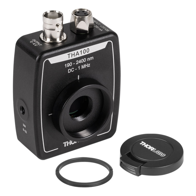
The low-profile housing of this detector enables use in optical paths with space constraints. Each housing features external SM1 (1.035"-40) threading, internal SM05 (0.535"-40) threading, and two universal mounting holes that accept both 8-32 and M4 x 0.7 threads, allowing for either vertical or horizontal post mounting. Additionally, an SM1T1 internally SM1-threaded coupler and SM1RR retaining ring are included with each detector, enabling convenient mounting of SM1-compatible accessories, optics, and cage assembly accessories. The internal SM05 threading is only suitable for mating to an externally SM05-threaded lens tube (components such fiber adapters cannot be threaded onto the SM05 threading). Externally SM1-threaded adapters should be mated to the included SM1T1 coupler, while internally SM1-threaded adapters can be mated directly to the housing. When using fiber adapters or other optics, make sure that the components do not crash into the detector. See the Mounting Options tab for more details.
Thorlabs offers a variety of amplified detectors based on different detector materials that include both free-space and fiber-coupled options. For our full selection of photodetectors, please see the Cross Reference tab.
| Item #a | Housing Featuresb |
Wavelength Range |
Max Pulse Detection Rate | Voltage Output | Sensitivity | Typical Performance Plots |
Active Area | Operating Temperature Range |
Power Supply Included |
|---|---|---|---|---|---|---|---|---|---|
| THA100 |  |
190 - 2400 nm | 1 MHz | 50 Ω: 0 - 2 V Hi-Z: 0 - 4 V |
Pulses <1 µs @ 1064 nm: 1500 V/Jc - 100 000 V/Jd QCWe >2 µs @ 1064 nm: 5 mV/Wc - 300 mV/Wd |
78.5 mm2 (Ø10 mm) | 10 to 40 °C | Yes |
| Table 2.1 Specificationsa | ||
|---|---|---|
| Item # | THA100 | |
| Detector Specifications | ||
| Detector | Tetrathiotetracene (TTT) Thermal Sensor | |
| Wavelength Range | 190 - 2400 nm | |
| Pulse Detection | 100 nJ - 1 mJ | |
| Average Power | 10 mW - 5 W | |
| Energy Density | 5 mJ/cm2 (Max) | |
| Average Power Density | 5 W/cm2 (Max) | |
| Peak Power Density | 100 kW/cm2 (Max) | |
| Max Pulse Detection Rate | 1 MHz | |
| Rise Time | 10 ns (Typ.) | |
| Fall Time | 800 ns (Typ.) | |
| Clear Aperture | Ø9 mm | |
| Detector Active Area | Ø10 mm (78.5 mm2) | |
| Output Voltage | 50 Ω | 0 to 2 V |
| Hi-Z | 0 to 4 V | |
| Sensitivity @ 1064 nm | Pulses <1 μs: 1500 V/Jb - 100 000 V/Jc QCWd >2 μs: 5 mV/Wb - 300 mV/Wc |
|
| Offset | ±10 mV | |
| Gain Adjustment | 8 Steps, 36 dB Dynamic Range (Typ.) | |
| Typical Performance Plotse | ||
| General Specifications | ||
| Electrical Output | BNC (DC Coupled), 50 Ω Impedance | |
| Housing Dimensionse | 2.79" x 2.10" x 0.89" (70.9 mm x 53.4 mm x 22.5 mm) |
|
|
||
| Detector Surface Depthf | 0.20" (5.0 mm) | |
| Weightg | 0.10 kg | |
| Included Accessories | SM1T1 Coupler SM1RR Retaining Ring SM1EC2B Dust Cap LDS12B Power Supply |
|
| Operating Temperature | 10 to 40 °C | |
| Storage Temperature | -25 to 70 °C | |
| Power Supply DC Output | ±12 V @ 250 mA | |
| Power Supply Input Voltage | 100 V / 120 V / 230 VAC, 50 - 60 Hz, Switchable | |
| Power Supply Output Power (Rated) | 6 W (Max) | |
| Table 2.2 Gain Settings | |||
|---|---|---|---|
| Gain Step | Gain (dB) | Gain (V/J) @ 1064 nm | Noise (mVpp) |
| 1 | 0 | 1500 | 1 |
| 2 | 6 | 3000 | 1.5 |
| 3 | 12 | 6000 | 2 |
| 4 | 18 | 12 000 | 4 |
| 5 | 24 | 24 000 | 7.5 |
| 6 | 30 | 48 000 | 12 |
| 7 | 33 | 75 000 | 15 |
| 8 | 36 | 100 000 | 20 |
Click to Enlarge
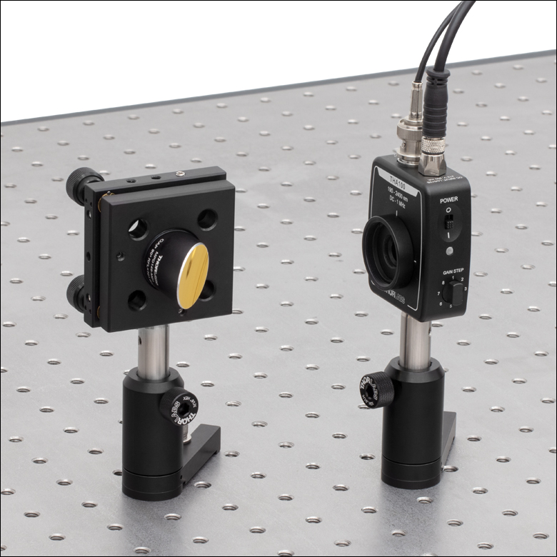
Figure 3.2 The THA100 detector is mounted vertically on a TR series post. In this configuration, the output and power cables are oriented vertically and away from the optic table, facilitating a neater optical setup

Click to Enlarge
Figure 3.1 The THA100 detector is mounted horizontally on a TR series post. In this configuration, the on/off switch and gain selector dial is conveniently oriented on the top of the detector.
Mounting Options for the THA100 Amplified Detector
The THA100 detector is compatible with our SM1- and SM05-threaded lens tubes, TR series posts, and can be integrated into cage systems. Because of the wide range of mounting options, the best method for mounting the housing in a given optical setup is not always obvious. Several common mounting solutions are discussed here.
TR Series Ø1/2" Post System
The THA100 housing can be mounted horizontally (Figure 3.1) or vertically (Figure 3.2) on a TR Series Post using either an 8-32 or M4 x 0.7 threaded screw, as the housing features universal 8-32 / M4 x 0.7 threads.
Lens Tube System
The THA100 housing includes a detachable SM1T1 internally SM1-threaded coupler that allows for mounting additional externally SM1-threaded optical components along the optical axis.
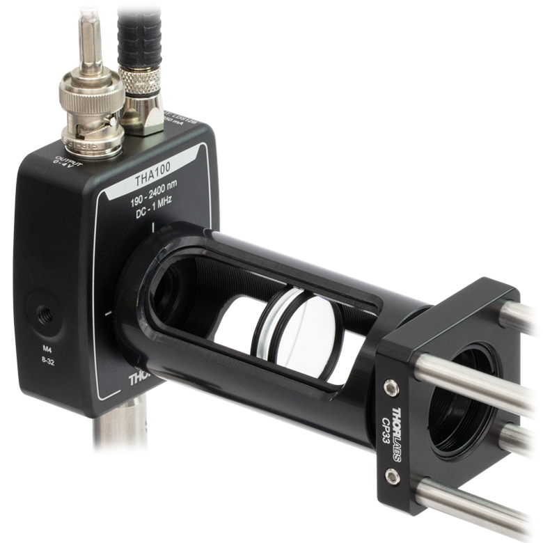
The external SM1 and internal SM05 threads on the detector housing make it compatible with our SM1 lens tube system and accessories, as shown in Figure 3.3. Two particularly useful accessories include the SM-threaded irises and the SM-compatible IR and visible alignment tools. Also available are fiber optic adapters for use with connectorized fibers.
Cage System
The simplest method for attaching the THA100 housing to a cage plate is to remove the SM1T1 coupler attached to the front of the detector housing and use the external SM1 threads. A cage plate, such as the CP33 30 mm cage plate, can be directly attached to the SM1 threads. Then an SM1RR retaining ring, included with the CP33 cage plate, can be threaded into the CP33 cage plate using a spanner wrench to ensure the cage plate is tightened to the desired location and square with the detector housing, as shown in Figure 3.4.
This method for attaching the THA100 detector housing to a cage plate does not allow much freedom in determining the orientation of the detector; however, it has the benefit of not needing an adapter piece, and it allows the diode to be as close as possible to the cage plate, which can be important in setups where the light is divergent.
For more freedom in choosing the orientation of the THA100 housing, an SM1T2 coupler can be threaded into the included SM1T1 adapter allowing a CP33 cage plate to be threaded onto the exposed SM1-threading and secured using one of the two locking rings included with the SM1T2 coupler, as shown in Figure 3.5.
The THA100 detector housing can also be connected to a 16 mm cage system by threading one side of an SM05T2 coupler to the detector housing and the other to an SP02 cage plate.
Click to Enlarge
Figure 3.3 The THA100 detector is mounted onto an SM1L30C Ø1" Slotted Lens Tube, which is housing an LA7656-E4 ZnSe lens. The lens tube is attached to a 30 mm cage system via a CP33 SM1-Threaded 30 mm Cage Plate. This arrangement allows easy access for optic adjustment and signal alignment.
Click to Enlarge
Figure 3.4 This picture shows a THA100 detector attached to a CP33 cage plate after removing the SM1T1. The retaining ring from the SM1T1 was used to make the orientation of the detector square with the cage plate.
Click to Enlarge
Figure 3.5 This picture shows a THA100 detector attached to a CP33 cage plate using an SM1T2 adapter in addition to the SM1T1 coupler that comes with the detector.
Male (Power Cable)
Figure 4.3 Shown above is the pin diagram for the power cable on the LDS12B power supply that is used with the THA100 detector.
Female Power IN (Photodetector)

Figure 4.2 Pin Diagram forTHA100 Power Connector
BNC Female Output (Photodetector)

Figure 4.1 THA100 Signal Output
50 Ω: 0 - 2 V
Hi-Z: 0 - 4 V
Pulsed Laser Emission: Power and Energy Calculations

Determining whether emission from a pulsed laser is compatible with a device or application can require referencing parameters that are not supplied by the laser's manufacturer. When this is the case, the necessary parameters can typically be calculated from the available information. Calculating peak pulse power, average power, pulse energy, and related parameters can be necessary to achieve desired outcomes including:
- Protecting biological samples from harm.
- Measuring the pulsed laser emission without damaging photodetectors and other sensors.
- Exciting fluorescence and non-linear effects in materials.
Pulsed laser radiation parameters are illustrated in Figure 170A and described in Table 170B. For quick reference, a list of equations is provided below. The document available for download provides this information, as well as an introduction to pulsed laser emission, an overview of relationships among the different parameters, and guidance for applying the calculations.
|
Equations: |
||||
 |
and |  |
||
 |
||||
 |
||||
 |
||||
Peak power and average power calculated from each other: |
||||
 |
and |  |
||
| Peak power calculated from average power and duty cycle*: | ||||
 |
*Duty cycle ( ) is the fraction of time during which there is laser pulse emission. ) is the fraction of time during which there is laser pulse emission. |
|||
Click to Enlarge
Figure 170A Parameters used to describe pulsed laser emission are indicated in this plot and described in Table 170B. Pulse energy (E) is the shaded area under the pulse curve. Pulse energy is, equivalently, the area of the diagonally hashed region.
| Table 170B Pulse Parameters | |||||
|---|---|---|---|---|---|
| Parameter | Symbol | Units | Description | ||
| Pulse Energy | E | Joules [J] | A measure of one pulse's total emission, which is the only light emitted by the laser over the entire period. The pulse energy equals the shaded area, which is equivalent to the area covered by diagonal hash marks. | ||
| Period | Δt | Seconds [s] | The amount of time between the start of one pulse and the start of the next. | ||
| Average Power | Pavg | Watts [W] | The height on the optical power axis, if the energy emitted by the pulse were uniformly spread over the entire period. | ||
| Instantaneous Power | P | Watts [W] | The optical power at a single, specific point in time. | ||
| Peak Power | Ppeak | Watts [W] | The maximum instantaneous optical power output by the laser. | ||
| Pulse Width |  |
Seconds [s] | A measure of the time between the beginning and end of the pulse, typically based on the full width half maximum (FWHM) of the pulse shape. Also called pulse duration. | ||
| Repetition Rate | frep | Hertz [Hz] | The frequency with which pulses are emitted. Equal to the reciprocal of the period. | ||
Example Calculation:
Is it safe to use a detector with a specified maximum peak optical input power of 75 mW to measure the following pulsed laser emission?
- Average Power: 1 mW
- Repetition Rate: 85 MHz
- Pulse Width: 10 fs
The energy per pulse:

seems low, but the peak pulse power is:

It is not safe to use the detector to measure this pulsed laser emission, since the peak power of the pulses is >5 orders of magnitude higher than the detector's maximum peak optical input power.
| Posted Comments: | |
user
(posted 2025-06-11 18:36:31.713) Hi,
do you have any data on the absorbtion for longer wavelength? We are interested in the behaviour at 3240 nm.
Best regards jjadvani
(posted 2025-06-13 09:30:01.0) Dear user, this detector is designed to use from 190-2400 nm. I will contact you directly to provide you further information. |
The following table lists Thorlabs' selection of photodiodes, photoconductive, and pyroelectric detectors. Item numbers in the same row contain the same detector element.
| Photodetector Cross Reference | ||||||
|---|---|---|---|---|---|---|
| Wavelength | Material | Unmounted Detectors |
Mounted Photodiode |
Biased Detector |
Amplified Detector |
Amplified Detector, OEM Package |
| 200 - 1100 nm | Si | FDS010 | SM05PD2A SM05PD2B |
DET10A2 | PDA10A2 | PDAPC5 |
| Si | - | SM1PD2A | - | - | - | |
| 240 - 1170 nm | Black Si | FDBS11 | SM05PD9A | - | - | - |
| Black Si | FDBS22 | SM05PD8A | DET20X2 | PDA20X2 | PDAPC10 | |
| Black Si | FDBS25 | - | - | - | - | |
| 320 - 1000 nm | Si | - | - | - | PDA8A2 | - |
| 320 - 1100 nm | Si | FD11A | SM05PD3A | - | PDF10A2 | - |
| Si | -a | - | DET100A2 | PDA100A2 | PDAPC2a | |
| 340 - 1100 nm | Si | FDS10X10 | - | - | - | - |
| 350 - 1100 nm | Si | FDS100 FDS100-CALb |
SM05PD1A SM05PD1B |
DET36A2 | PDA36A2 | PDAPC1 |
| Si | FDS1010 FDS1010-CALb |
SM1PD1A SM1PD1B |
- | - | - | |
| 400 - 1000 nm | Si | - | - | - | PDA015A2 FPD310-FS-VIS FPD310-FC-VIS FPD510-FC-VIS FPD510-FS-VIS FPD610-FC-VIS FPD610-FS-VIS |
- |
| 400 - 1100 nm | Si | FDS015c | - | - | - | - |
| Si | FDS025c FDS02d |
- | DET02AFC(/M) DET025AFC(/M) DET025A(/M) DET025AL(/M) |
- | - | |
| 400 - 1700 nm | Si & InGaAs | DSD2 | - | - | - | - |
| 500 - 1700 nm | InGaAs | - | - | DET10N2 | - | - |
| 0.6 - 16 µm | LiTaO3 | EPD13e | - | - | PDA13L2e | - |
| 750 - 1650 nm | InGaAs | - | - | - | PDA8GS | - |
| 800 - 1700 nm | InGaAs | FGA015 | - | - | PDA015C2 | - |
| InGaAs | FGA21 FGA21-CALb |
SM05PD5A | DET20C2 | PDA20C2 PDA20CS2 |
- | |
| InGaAs | FGA01c FGA01FCd |
- | DET01CFC(/M) | - | - | |
| InGaAs | FDGA05c | - | - | PDA05CF2 | PDAPC6 | |
| InGaAs | - | - | DET08CFC(/M) DET08C(/M) DET08CL(/M) |
- | - | |
| InGaAs | - | - | - | PDF10C2 | - | |
| 800 - 1800 nm | Ge | FDG03 FDG03-CALb |
SM05PD6A | DET30B2 | PDA30B2 | - |
| Ge | FDG50 | - | DET50B2 | PDA50B2 | PDAPC8 | |
| Ge | FDG05 | - | - | - | - | |
| 900 - 1700 nm | InGaAs | FGA10 | SM05PD4A | DET10C2 | PDA10CS2 | - |
| 900 - 2600 nm | InGaAs | FD05D | - | DET05D2 | - | - |
| FD10D | - | DET10D2 | PDA10D2 | PDAPC7 | ||
| 950 - 1650 nm | InGaAs | - | - | - | FPD310-FC-NIR FPD310-FS-NIR FPD510-FC-NIR FPD510-FS-NIR FPD610-FC-NIR FPD610-FS-NIR |
- |
| 1.0 - 5.8 µm | InAsSb | - | - | - | PDA10PT(-EC) | - |
| 2.0 - 8.0 µm | HgCdTe (MCT) | VML8T0f VML8T4f,g |
- | - | PDAVJ8f | - |
| 2.0 - 10.6 µm | HgCdTe (MCT) | VML10T0f VML10T4f,g |
- | - | PDAVJ10f | - |
| 2.7 - 5.0 µm | HgCdTe (MCT) | VL5T0f | - | - | PDAVJ5f | - |
| 2.7 - 5.3 µm | InAsSb | - | - | - | PDA07P2 | PDAPC9 |