 Products Home / Optical Tables, Breadboards, and Supports / Solid Aluminum Optical Breadboards / Large-Area Rotating Breadboards
Large-Area Rotating Breadboards

- Removable Center Allows
Rotation Around Components - Simple, Hand-Operated
Positioning
RBB12A
Position Locking
Screw
Position Locking
Screw
RBBA1
SM1-Threaded Center Insert
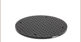
Removable Center Portion
Measuring Ø3.58" (Ø91.0 mm)


Please Wait
Click to Enlarge
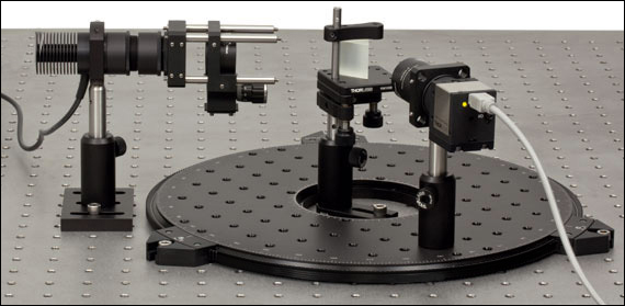
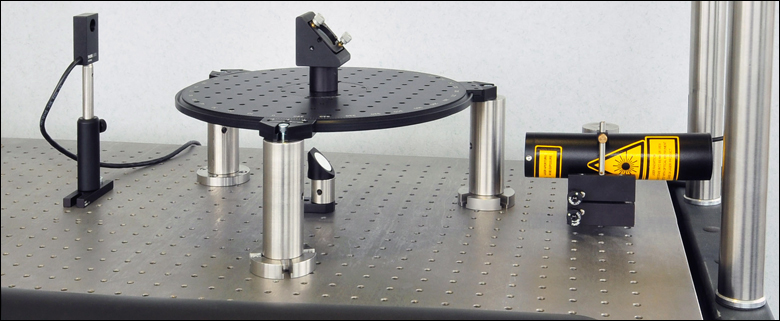
Figure 1.2 Prism Spectroscope Using the RBB12A Rotating Breadboard (See Application Idea Tab for Details)
Click for Details
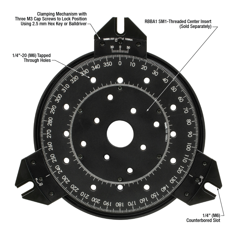
Figure 1.1 RBB6A with Optional RBBA1 SM1-Threaded Center Insert
Click to Enlarge
Figure 1.3 A laser beam is passed through the central aperture of an RBB12A rotating breadboard to a mirror mount secured with an RBBA1
Features
- 360° Continuous, Hand-Operated Rotation
- Ø6" (Ø150 mm), Ø12" (Ø300 mm), or Ø18" (Ø450 mm) Sizes
- Standard 1/4"-20 (1" Pitch) or M6 x 1.0 (25 mm Pitch) Hole Patterns
- 0.50" (12.7 mm) Thickness
- Position-Locking Mechanism
- Black Anodized Aluminum Construction
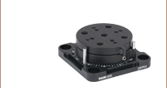
These Large-Area Rotating Breadboards are available in three sizes with standard 1/4"-20 or M6 x 1.0 hole patterns: Ø6" (Ø150 mm), Ø12" (Ø300 mm), or Ø18" (Ø450 mm). The hole patterns feature 1" or 25 mm centers. The breadboard thickness is 0.50" (12.7 mm), which is the same as our standard solid aluminum breadboards. These breadboards are designed for use in applications requiring coarse angular adjustment of optical assemblies. Each breadboard features a removable Ø91.0 mm (Ø3.58") center section, allowing components to be placed at the center while the breadboard rotates around them (see Figure 1.2). A laser-etched scale around the edge of the rotating surface has 1° graduations. Positioning is achieved by rotating the platform by hand.
The breadboard features a dovetailed edge and three lockable kinematic mounts that can be positioned anywhere around the perimeter via the three locking screws using the included 2.5 mm hex key. The mounts also incorporate slotted holes that, together with their adjustable positioning, allow flexibility when the breadboard is secured to an optical table or other work surface. Figure 1.2 shows a prism spectroscope built using the RBB12A; see the Application Idea tab for details about this setup.
The Ø91 mm (Ø3.58") middle section of the breadboard can be replaced with an RBBA1(/M) center insert (sold separately) that features an SM1-threaded (1.035"-40) central aperture. By mounting the rotation breadboard on posts, this insert allows light to be directed upwards from a mirror mounted underneath the breadboard's surface. Optics can then be mounted using the insert for use in a variety of applications, such as the setup in Figure 1.3. In this setup, an RBB12A breadboard rotates around an elliptical optic mount, which was mounted via the RBBA1 insert. Using a mirror mounted underneath the rotation breadboard, a laser beam is deflected through the center of the breadboard and onto a second mirror that directs the beam onto a detector. When the breadboard is post mounted, ensure the clamps are not too tightly assembled. Overtightened screws will prevent the breadboard from rotating. Note that the breadboard will require more torque to rotate with heavier loads mounted on the platform.
| Item # | RBB6A and RBB150A/M | RBB12A and RBB300A/M | RBB18A and RBB450A/M |
|---|---|---|---|
| Travel Range | 360° Continuous | ||
| Working Height | 0.5" (12.7 mm) | ||
| Load Capacity (Max) | 20 kg (44 lbs)a | ||
| Taps | RBB6A, RBB12A and RBB18A: 1/4"-20 on 1" Pitch RBB150A/M, RBB300A/M and RBB450A/M: M6 on 25 mm Pitch |
||
| Max Vertical Run Out Over Full Travel | 25 μm | 50 μm | 75 μm |
| Max Horizontal Run Out Over Full Travel | 25 μm | 50 μm | 75 μm |
| Overall Dimensions (Excluding Clamps) | Ø6.64" (164 mm) | Ø12.4" (314 mm) | Ø18.27" (464 mm) |
| Platform Dimensions | Ø5.91" (150 mm) | Ø11.8" (300 mm) | Ø17.72" (450 mm) |
| Weight | 1.76 lb (0.8 kg) | 5.5 lb (2.5 kg) | 6.6 lb (3.0 kg) |
| Construction | Solid Aluminum | ||
| Finish | Black Anodized | ||
Prism Spectroscope

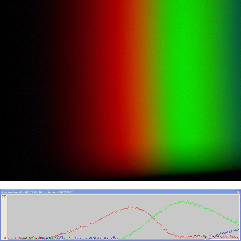
A prism spectroscope is an instrument often used in undergraduate optics labs to measure the wavelength of atomic vapor transitions. In our version of this classic experiment, we image the spectrum of a white light LED using a previous-generation DCU223C color CCD camera. The large mounting surface of the rotating breadboard could easily mount other components, such as additional detectors, which could then be precisely rotated into and out of the beam path. To build a similar set-up, refer to Tables 3.1 and 3.2 corresponding with either the imperial or metric list of parts. Click on the item number to bring up a pop-up window with more information about that component.
Note: The previous-generation DCU223C color CCD camera is not available for individual purchase. For use in your application, please consider our line of 1.6 MP CMOS Compact Scientific Cameras. These cameras are available with either a monochrome or color CMOS sensor, are compatible with a USB 3.0 interface, and are compatible with our 30 mm Cage Systems.
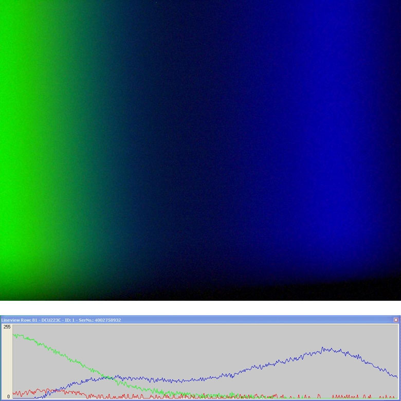
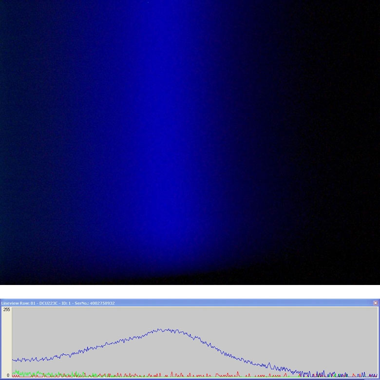
Prism Spectroscope Images
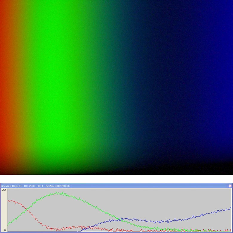
Figures 3.3 through 3.6 show four still images that were taken by rotating the camera on the breadboard. The plots below the graph show the relative red, green, and blue intensity of a horizontal line of pixels within the corresponding CCD image. Please note that the images do overlap each other slightly.
Click to Enlarge
Figure 3.3 LED Spectrum Image 1
Click to Enlarge
Figure 3.4 LED Spectrum Image 2
Click to Enlarge
Figure 3.5 LED Spectrum Image 3
Click to Enlarge
Figure 3.6 LED Spectrum Image 4
Reading a Vernier Scale on a Linear Main Scale
Vernier scales are typically used to add precision to standard, evenly divided scales (such as the scales on Thorlabs' rotation, goniometric, or translation mounts). A vernier scale has found common use in many precision measurement instruments, the most common being calipers and micrometers. The vernier scale uses two scales side-by-side: the main scale and the vernier scale. The direct vernier scale has a slightly smaller spacing between its tick marks owing to the vernier scale having N ticks for every N - 1 ticks on the main scale. Hence, the lines on the main scale will not line up with all the lines on the vernier scale. Only one line from the vernier scale will match well with one line of the main scale, and that is the trick to reading a vernier scale.
Figures 130A through 130C show a linear vernier scale system for three different situations. In each case, the scale on the left is the main scale, while the small scale on the right is the vernier scale. When reading a vernier scale, the main scale is used for the gross number, and the vernier scale gives the precision value. In this manner, a standard ruler or micrometer can become a precision instrument.
The 0 on the vernier scale is the "pointer" (marked by a red arrow in Figures 130A through 130E) and will indicate the main scale reading. In Figure 130A we see the pointer is lined up directly with the 75.6 line. Notice that the only other vernier scale tick mark that lines up well with the main scale is 10. Since the pointer lines up with the main scale’s 75.6, the reading from Figure 130A is 75.60 (in whatever units the instrument measures).
That is essentially all there is to reading a vernier scale. It's a very straightforward way of increasing the precision of a measurement instrument. To expound, let’s look at Figure 130B. Here we see that the pointer is no longer aligned with a line on the main scale, but instead it is slightly above 75.6 and below 75.7; thus, the gross measurement is 75.6. The first vernier line that coincides with a main scale line is the 5, shown with a blue arrow. The vernier scale gives the final digit of precision; since the 5 is aligned to the main scale, the precision measurement for Figure 130B is 75.65.
Since this vernier scale is 10% smaller than the main scale, moving the vernier scale by 1/10 of the main scale will align the next vernier marking. This asks the obvious question: what if the measurement is within the 1/10 precision of the vernier scale? Figure 130C shows just this. Again, the pointer line is in between 75.6 and 75.7, yielding the gross measurement of 75.6. If we look closely, we see that the vernier scale 7 (marked with a blue arrow) is very closely aligned to the main scale, giving a precision measurement of 75.67. However, the vernier scale 7 is very slightly above the main scale mark, and we can see that the vernier scale 8 (directly above 7) is slightly below its corresponding main scale mark. Hence, the scale on Figure 130C could be read as 75.673 ± 0.002. A reading error of about 0.002 would be appropriate for
this instrument.
Click to Enlarge
Figure 130A An example of how to read a vernier scale. The red arrow indicates what is known as the pointer. Since the tick mark labeled 10 on the vernier scale aligns with one of the tick marks on the main scale, this vernier scale is reading 75.60 (in whatever units the instrument measures).

Click to Enlarge
Figure 130B The red arrow indicates the pointer and the blue arrow indicates the vernier line that matches the main scale. This scale reads 75.65.
Click to Enlarge
Figure 130C The red arrow indicates the pointer, and the blue arrow indicates the vernier line that matches the main scale. This scale reads 75.67 but can be accurately read as
75.673 ± 0.002.
Reading a Vernier Scale on a Rotating Main Scale
The vernier scale may also be used on rotating scales where the main scale and vernier scale do not share units. Figures 130D and 130F show a vernier scale system for two different situations where the main scale is given in degrees and the vernier scale has ticks every 5 arcmin (60 arcmin = 1°). In each case, the scale on the top is the main scale, while the small scale on the bottom is the vernier scale.
In Figure 130D we see the pointer is lined up directly with the 341° line. Notice that the only other vernier scale tick marks that line up well with the main scale are ±60 arcmin. Since the pointer lines up with the main scale at 341°, the reading from Figure 130D is 341.00°.
There are two ways to determine the reading if the zero on the vernier scale line is between two lines of the main scale. For the first method, take the line on the left side of the pointer on the vernier scale and subtract that value (in arcmin) from the value on the main scale that is to the right on the main scale. As an example, in Figure 130E the vernier pointer is between 342° and 343°; using the left blue arrow of the vernier scale results in
As we've seen here, vernier scales add precision to a standard scale measurement. While it takes a bit of getting used to, with a little practice, reading these scales is fairly straightforward. Vernier scales, whether they are direct or retrograde*, are read in the same fashion.
*A retrograde vernier scale has a larger spacing between its tick marks with N ticks for every N + 1 ticks on the main scale.
Click to Enlarge
Figure 130D An example of a vernier scale where the main scale and the vernier scale are in different units (degrees and arcmins, respectively). The red arrow indicates the pointer. This scale reads 341.00°.
Click to Enlarge
Figure 130E The red arrow indicates the pointer and the blue arrows give the precision value from the vernier scale.
This scale reads 342.75°.
| Posted Comments: | |
Gabriel Undeutsch
(posted 2022-07-26 15:21:16.75) 1. I have a question regarding adding a fine screw. We have such Large Area Rotation boards and where wondering whether there is the possiblitity to add a fine screw for the roation. Is there any such system avaliable?
2. Is the removable center portion always included when ordering? Is it possible to order it alone? cwright
(posted 2022-07-27 02:54:55.0) Response from Charles at Thorlabs: Thank you for your query. This breadboard does come with the removable centre portion and we can provide it as a separate item as a special upon request. Unfortunately there is not a dedicated way to add fine rotation to this breadboard. You could pottentially use kinematic positioners to achieve this. I will reach out to you to help with this. Stephen McLaughlin
(posted 2019-05-13 10:27:55.657) I have the RBB18A mounted on 4" tall posts (1" diameter). However, it's extremely difficult to turn. Is there some way to improve the needed torque for this? I find that I have to lift the board against the mounts to turn it. (I have 3 mirrors, 2 XYZ position mounts, and a 3 lb weight on it).
I've made sure the locking screws are loose and ready to turn, but nothing has made this thing easier to turn. In my experience with it, it's not much in the way of rotation. (I also expected some sort of bearing setup, not 3 plastic clips and a dovetail connection). bhallewell
(posted 2019-05-14 04:43:56.0) Response from Ben at Thorlabs: Thank you for your feedback. I'll contact you directly to discuss this with you. The first thing to ensure is that the locking screws are not tightened. Additionally, as this is an aluminium dovetail design, the more load which is applied to the breadboard will cause the board to flex when clamped to 1” posts. The location of such posts on the mounting surface will also contribute to the torque required to move the platform. High load will naturally increase the friction between the breadboard & the clamps, increasing the torque required to rotate the platform. Hugo.Diaz
(posted 2018-02-15 08:42:34.073) Large-Area Rotation Stage RBB18A
If I set up the stage in a vertical manner, what will be the maximum wait allowed to mount without damage it.
Thanks,
Hugo bwood
(posted 2018-02-21 04:05:33.0) Response from Ben at Thorlabs: Thank you for your feedback. The mounting clamps of the RBB series rotating breadboard are not designed to carry the full weight of the breadboard, and they will likely be damaged if the breadboard is mounted vertically in any orientation. Thus we advise that the RBB series breadboards should not be mounted vertically, and should only be mounted horizontally. Stephen.Turner
(posted 2017-02-27 07:57:01.383) Is the Large-Area Rotation Stage completely non-magnetic? bhallewell
(posted 2017-03-01 05:06:10.0) Response from Ben at Thorlabs: The breadboard body is anodised aluminium & contains components of delrin & stainless steel (screws). The stainless steel screws are the only magnetic components within the construction of the product. ron.schulze
(posted 2017-02-08 15:26:46.883) Is there a moment loading specification that we need to maintain for the RBB12A product? bhallewell
(posted 2017-02-09 10:07:19.0) Response from Ben at Thorlabs: We spec an on-axis load of 20 kg (44 lbs) however we do not hold a spec for moment load. I will contact you directly to discuss the suitability of the product for your application. tcohen
(posted 2012-10-18 14:28:42.413) Response from Tim at Thorlabs: I apologize that you’re not satisfied with the performance of your unit. We will of course offer a repair if the unit is not performing. We have contacted you directly to provide support. |