 Products Home / Technical Resources / Optical Isolators Technical Publications / Optical Isolator Tutorial
Optical Isolator Tutorial

Please Wait
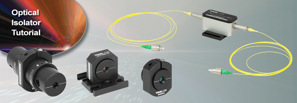
Thorlabs manufactures a wide selection of narrowband and broadband free-space optical isolators (Faraday isolators) that operate in spectral ranges from 365 nm to 4550 nm, including high-power options, as well as fiber isolators designed for wavelength ranges from 650 to 2010 nm for polarization-independent versions and 770 nm to 2010 nm for polarization-dependent versions. For customers whose needs are not met by our stock selection, we offer a custom isolator service that can combine the best features across our entire isolator family.
 Figure 2.1 Fixed Narrowband Isolation
Fixed Narrowband Isolator
The isolator is set for 45° of rotation at the design wavelength. The polarizers are non-adjustable and are set to provide maximum isolation at the design wavelength. As the wavelength changes the isolation will drop; Figure 2.1 shows a representative profile.
- Fixed Rotator Element, Fixed Polarizers
- Polarization Dependent
- Smallest and Least Expensive Isolator Type
- No Tuning
 Figure 2.2 Adjustable Narrowband Isolation
Adjustable Narrowband Isolator
The isolator is set for 45° of rotation at the design wavelength. If the usage wavelength changes, the Faraday rotation will change, thereby decreasing the isolation. To regain maximum isolation, the output polarizer can be rotated to "re-center" the isolation curve. This rotation causes transmission losses in the forward direction that increase as the difference between the usage wavelength and the design wavelength grows.
- Fixed Rotator Element, Adjustable Polarizers
- Polarization Dependent
- General-Purpose Isolator
 Figure 2.3 Adjustable Broadband Isolation
Adjustable Broadband Isolator
The isolator is set for 45° of rotation at the design wavelength. There is a tuning ring on the isolator that adjusts the amount of Faraday rotator material that is inserted into the internal magnet. As your usage wavelength changes, the Faraday rotation will change, thereby decreasing the isolation. To regain maximum isolation, the tuning ring is adjusted to produce the 45° of rotation necessary for maximum isolation.
- Adjustable Rotator Element, Fixed Polarizers
- Polarization Dependent
- Simple Tuning Procedure
- Broader Tuning Range than Adjustable Narrowband Isolators
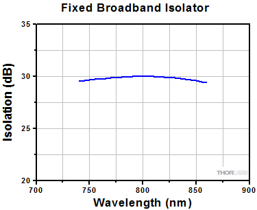 Figure 2.4 Fixed Broadband Isolation
Fixed Broadband Isolator
A 45° Faraday rotator is coupled with a 45° crystal quartz rotator to produce a combined 90° rotation on the output. The wavelength dependences of the two rotator materials work together to produce a flat-top isolation profile. The isolator does not require any tuning or adjustment for operation within the designated design bandwidth.
- Fixed Rotator Element, Fixed Polarizers
- Polarization Dependent
- Largest Isolation Bandwidth
- No Tuning Required
 Figure 2.5 Tandem Isolation
Tandem Isolators
Tandem isolators consist of two Faraday rotators in series, which share one central polarizer. Since the two rotators cancel each other, the net rotation at the output is 0°. Our tandem designs yield narrowband isolators that may be fixed or adjustable.
- Up to 60 dB Isolation
- Polarization Dependent
- Highest Isolation
- Fixed or Adjustable
Optical Isolator Tutorial
Function
An optical isolator is a passive magneto-optic device that only allows light to travel in one direction. Isolators are used to protect a source from back reflections or signals that may occur after the isolator. Back reflections can damage a laser source or cause it to mode hop, amplitude modulate, or frequency shift. In high-power applications, back reflections can cause instabilities and power spikes.
An isolator's function is based on the Faraday Effect. In 1842, Michael Faraday discovered that the plane of polarized light rotates while transmitting through glass (or other materials) that is exposed to a magnetic field. The direction of rotation is dependent on the direction of the magnetic field and not on the direction of light propagation; thus, the rotation is non-reciprocal. The amount of rotation Q equals V x L x H, where V, L, and H are as defined below.

Figure 3.1 Faraday Rotator's Effect on Linearly Polarized Light
Faraday Rotation
Q = V x L x H
V: the Verdet Constant, a property of the optical material, in minutes/Oersted-cm.
L: the path length through the optical material in cm.
H: the magnetic field strength in Oersted.
An optical isolator consists of an input polarizer, a Faraday rotator with magnet, and an output polarizer. The input polarizer works as a filter to allow only linearly polarized light into the Faraday rotator. The Faraday element rotates the input light's polarization by 45°, after which it exits through another linear polarizer. The output light is now rotated by 45° with respect to the input signal. In the reverse direction, the Faraday rotator continues to rotate the light's polarization in the same direction that it did in the forward direction so that the polarization of the light is now rotated 90° with respect to the input signal. This light's polarization is now perpendicular to the transmission axis of the input polarizer, and as a result, the energy is either reflected or absorbed depending on the type of polarizer.
Figure 3.2 A polarization-dependent isolator. Light propagating in the reverse direction is rejected by the input polarizer.
Polarization-Dependent Isolators
The Forward Mode
In this example, we will assume that the input polarizer's axis is vertical (0° in Figure 3.2). Laser light, either polarized or unpolarized, enters the input polarizer and becomes vertically polarized. The Faraday rotator will rotate the plane of polarization (POP) by 45° in the positive direction. Finally, the light exits through the output polarizer which has its axis at 45°. Therefore, the light leaves the isolator with a POP of 45°.
The Reverse Mode
Light traveling backwards through the isolator will first enter the output polarizer, which polarizes the light at 45° with respect to the input polarizer. It then passes through the Faraday rotator rod, and the POP is rotated another 45° in the positive direction. This results in a net rotation of 90° with respect to the input polarizer, and thus, the POP is now perpendicular to the transmission axis of the input polarizer. Hence, the light will either be reflected or absorbed.
 Click for Details
Figure 3.3 A polarization independent isolator. Light is deflected away from the input path and stopped by the housing.
Polarization-Independent Fiber Isolators
The Forward Mode
In a polarization independent fiber isolator, the incoming light is split into two branches by a birefringent crystal (see Figure 3.3). A Faraday rotator and a half-wave plate rotate the polarization of each branch before they encounter a second birefringent crystal aligned to recombine the two beams.
The Reverse Mode
Back-reflected light will encounter the second birefringent crystal and be split into two beams with their polarizations aligned with the forward mode light. The faraday rotator is a non-reciprocal rotator, so it will cancel out the rotation introduced by the half wave plate for the reverse mode light. When the light encounters the input birefringent beam displacer, it will be deflected away from the collimating lens and into the walls of the isolator housing, preventing the reverse mode from entering the input fiber.
General Information
Damage Threshold
With 25 years of experience and 5 U.S. patents, our isolators typically have higher transmission and isolation than other isolators, and are smaller than other units of equivalent aperture. For visible to YAG laser Isolators, Thorlabs' Faraday Rotator crystal of choice is TGG (terbium-gallium-garnet), which is unsurpassed in terms of optical quality, Verdet constant, and resistance to high laser power. Thorlabs' TGG Isolator rods have been damage tested to 22.5 J/cm2 at 1064 nm in 15 ns pulses (1.5 GW/cm2), and to 20 kW/cm2 CW. However, Thorlabs does not bear responsibility for laser power damage that is attributed to hot spots in the beam.
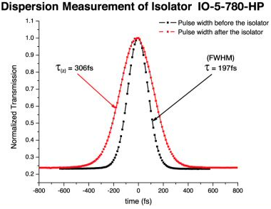
Figure 3.4 Pulse Dispersion Measurements Before and After an
Magnet
The magnet is a major factor in determining the size and performance of an isolator. The ultimate size of the magnet is not simply determined by magnetic field strength but is also influenced by the mechanical design. Many Thorlabs magnets are not simple one piece magnets but are complex assemblies. Thorlabs' modeling systems allow optimization of the many parameters that affect size, optical path length, total rotation, and field uniformity. Thorlabs' US Patent 4,856,878 describes one such design that is used in several of the larger aperture isolators for YAG lasers. Thorlabs emphasizes that a powerful magnetic field exists around these Isolators, and thus, steel or magnetic objects should not be brought closer than 5 cm.
Temperature
The magnets and the Faraday rotator materials both exhibit a temperature dependence. Both the magnetic field strength and the Verdet Constant decrease with increased temperature. For operation greater than ±10 °C beyond room temperature, please contact Technical Support.
Pulse Dispersion
Pulse broadening occurs anytime a pulse propagates through a material with an index of refraction greater than 1. This dispersion increases inversely with the pulse width and therefore can become significant in ultrafast lasers.
τ: Pulse Width Before Isolator
τ(z): Pulse Width After Isolator
Example:
t = 197 fs results in t(z) = 306 fs (pictured in Figure 3.4)
t = 120 fs results in t(z) = 186 fs
| Posted Comments: | |
Jim Zhang
(posted 2025-02-27 16:31:32.07) For your optical isolator products, what is their operation temperature effect? For example, for any of your isolator if I operate it at 50C base temperature instead of room temperature (20 - 25 C), what is its transmission and isolation change? cdolbashian
(posted 2025-03-19 12:16:49.0) Thank you for reaching out to us with this request. The transmission should not change much, but you will likely see a reduction in the Faraday rotation through the magneto-optic material and thus reduced efficacy of the isolation function. That being said, it is possible that we can tune the device at a higher temperature here as a custom such that it has optimal performance at your expected operating temp. I have contacted you directly to discuss this option. |