 Products Home / Optical Fiber & Fiber Patch Cables / Single Mode Fiber Optic Patch Cables / High-Power, End-Capped Single Mode Fiber Optic Patch Cables
High-Power, End-Capped Single Mode Fiber Optic Patch Cables
- Coreless End Cap for High-Power Applications
- One FC/PC Connector with End Cap, AR Coated for 1030 - 1120 nm
- One Uncoated FC/APC Connector or Scissor-Cut End
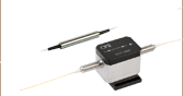
P9-1064HE-2
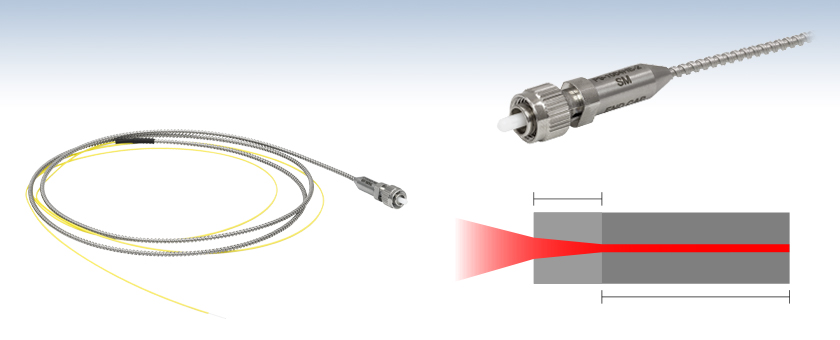
AR-Coated, End-Capped FC/PC Connector to Scissor-Cut End
FC/PC-Terminated End has AR Coating and Coreless End Cap
Coreless End Cap
Standard Optical Fiber


Please Wait
| Stock Single Mode Patch Cables Selection Guide | |
|---|---|
| Standard Cables | FC/PC to FC/PC |
| FC/APC to FC/APC | |
| Hybrid | |
| AR-Coated Patch Cables | |
| HR-Coated Patch Cables | |
| Beamsplitter-Coated Patch Cables | |
| High-Power, End-Capped Patch Cables | |
| MIR Fluoride Fiber Patch Cables | |
Operation Notes
The AR-coated, FC/PC connector is meant for free-space applications only and will be damaged if it comes into contact with another connector tip.The FC/APC connector
Features
- Coreless End Cap Reduces Intensity at Air-to-Glass Interface
- One FC/PC Connector with End Cap and AR V-Coating for 1064 nm
- One Uncoated FC/APC or Scissor-Cut End
- Fiber Type: SM980-5.8-125 Single Mode Fiber
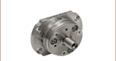
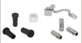
- Stainless Steel Tubing, Extra Metal Caps Included
- See Handling Tab for Guidelines for High-Power Applications
Thorlabs offers patch cables with a coreless end cap and an antireflection-coated FC/PC connector on one end. The AR coating provides <0.25% reflectance in the 1030 - 1120 nm range and minimizes reflections when launching out of the fiber into free space. The end cap reduces the power density to a level below the damage threshold, making the FC/PC connectors on these patch cables capable of handling CW powers of up to 15 W.
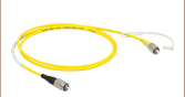
Item # P5-1064HE-2 has one FC/PC connector with an end cap and an AR coating, and one uncoated FC/APC connector.
Note: the FC/APC connector does not contain a coreless end cap and should not be used at powers above 1 W if mated to another FC/APC connector, or above 300 mW in fiber-to-free space coupling.
Item # P9-1064HE-2 has one FC/PC connector with an end cap and an AR coating, and one scissor-cut end. For fiber splicing supplies, see our fiber cleavers, termination tools, and fiber splicers.
When coupling or collimating light with these patch cables, we advise starting with the beam at very low power. After ensuring the beam is properly aligned and the coupling efficiency is optimal, slowly increase the power to the desired level. Please see the Handling tab and the Damage Threshold tab for other special guidelines for handling high-power fiber optic cables.
Fiber-to-Free Space Coupling
When coupling from a fiber into free space, such as when using one of our adjustable fiber collimators or FiberPort collimators/couplers, the return loss will be higher than comparable values for fiber-to-fiber coupling. However, the end cap on the fiber end face improves the return loss of the FC/PC connectors by 21 dB at 1064 nm. The AR V-coating further improve the return loss to 47 dB over the range of 1030 - 1120 nm, and to approximately 55 dB at 1064 nm.
Note: The AR-coated end is meant for free-space applications (e.g., collimation) and will be damaged if it comes into contact with another connector tip.
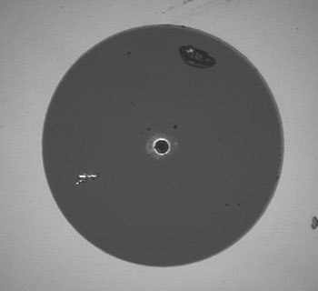
Click to Enlarge
Figure 1.2 Cross Section of Standard Fiber vs. Coreless Fiber
Prevent Laser-Induced Damage
These patch cables are end-capped with a coreless termination fiber to protect them from laser-induced damage. Without an end cap, the beam diameter of light entering or exiting the fiber must match the core size. This can create a high power density at the air-to-glass interface and cause damage when the intensity is beyond the damage threshold. However, the end cap contains no waveguide. Thus, the light path is not confined and can enter or exit the end cap with a larger beam diameter, as shown in Figure 1.1. This reduces the optical power density at the air-to-glass interface and helps to prevent damage.
Custom end-capped patch cables are also available; contact Tech Support for details. Thorlabs can also manufacture these cables in custom lengths and with certain custom fibers. Please contact your local Tech Support office for assistance in ordering these items.
Handling
IMPORTANT NOTE: Before using these fibers with your equipment, make sure that you are familiar with all operating and safety instructions provided with your light source. Carefully read the below information; proper operation and handling of these devices is imperative to prevent damage to fiber and related equipment.
1. Before attaching the provided fibers to your system, inspect both the input and output connector ends. The end faces should be clean and as free from contamination as possible. If not, clean the ends as outlined in the cleaning section below. Check the fiber ends both before connecting the fiber and also after disconnecting the fiber. It is very easy for contaminants to be transferred from one connector to another if proper care is not taken.
2. To avoid damage to the fibers being used, turn the source off, or reduce the power level to less than 50 mW before attaching the fiber. If any optics have to be aligned, then perform the initial alignment at low power (<50 mW). Only after the optics are fully aligned and locked should the laser power be increased.
3. It is recommended that the laser power be increased by only 250 mW every few minutes, and that the output power from the fiber should be monitored, to ensure that the coupling efficiency is not changing with power.
4. The beam must be free from hot spots (localized energy spikes). If hot spots are present in the beam then the energy density must be calculated for that localized area to ensure it doesn't exceed the damage threshold of the fiber.
5. The energy must be well within the MFD of the fiber. For example, if the MFD is 6.0 ± 0.5 µm, then the input beam should be ≤5.1 µm (i.e. 10% below the minimum possible MFD).
6. Do not use any index matching gel, thread locking fluid, or any lubricants with the connector. Do not use in the presence of chemical fumes or oils.
7. Products must be used in a clean environment in order to ensure spotless end faces. Any speck of dust adhering to the end face can easily lead to the degradation or destruction of the fiber.
Mating
The AR-coated, FC/PC connectors are not designed to be mated with other patch cables and should not be used in mating sleeves or fixed attenuators. The coating will be damaged if it comes into contact with another connector tip. The uncoated, FC/APC connector on the P5-1064HE-2 can be mated to another FC/APC connector with a mating sleeve.
Cleaning
Use filtered compressed air to blow any dust or dirt off the ferrule when finished. Do not use any type of cleaning solution such as isopropyl alcohol to clean fiber end face. Carefully inspect the tip of the fiber with fiber scope. The tip should be free of all contaminants. Continually clean the caps and the fiber tip before and after each use to help prevent contamination. See our fiber optic cleaning products for cleaning supplies.
When not in use, the ends of the fiber and the connector receptacles should be covered with the supplied caps. This will help protect the connectors from dirt and contamination. It is only recommended to use the dust caps supplied with the cables. Only the Thorlabs caps supplied with the cable are approved for use in sterilization procedures. Any other caps often are contaminated with mold release agents, which can get onto the fiber ends. This contamination is extremely difficult to see, and resists cleaning.
| Quick Links |
|---|
| Damage at the Air / Glass Interface |
| Intrinsic Damage Threshold |
| Preparation and Handling of Optical Fibers |
Laser-Induced Damage in Silica Optical Fibers
The following tutorial details damage mechanisms relevant to unterminated (bare) fiber, terminated optical fiber, and other fiber components from laser light sources. These mechanisms include damage that occurs at the air / glass interface (when free-space coupling or when using connectors) and in the optical fiber itself. A fiber component, such as a bare fiber, patch cable, or fused coupler, may have multiple potential avenues for damage (e.g., connectors, fiber end faces, and the device itself). The maximum power that a fiber can handle will always be limited by the lowest limit of any of these damage mechanisms.
While the damage threshold can be estimated using scaling relations and general rules, absolute damage thresholds in optical fibers are very application dependent and user specific. Users can use this guide to estimate a safe power level that minimizes the risk of damage. Following all appropriate preparation and handling guidelines, users should be able to operate a fiber component up to the specified maximum power level; if no maximum is specified for a component, users should abide by the "practical safe level" described below for safe operation of the component. Factors that can reduce power handling and cause damage to a fiber component include, but are not limited to, misalignment during fiber coupling, contamination of the fiber end face, or imperfections in the fiber itself. For further discussion about an optical fiber’s power handling abilities for a specific application, please contact Thorlabs’ Tech Support.

Damage at the Air / Glass Interface
There are several potential damage mechanisms that can occur at the air / glass interface. Light is incident on this interface when free-space coupling or when two fibers are mated using optical connectors. High-intensity light can damage the end face leading to reduced power handling and permanent damage to the fiber. For fibers terminated with optical connectors where the connectors are fixed to the fiber ends using epoxy, the heat generated by high-intensity light can burn the epoxy and leave residues on the fiber facet directly in the beam path.
| Table 36C Estimated Optical Power Densities on Air / Glass Interfacea | ||
|---|---|---|
| Type | Theoretical Damage Thresholdb | Practical Safe Levelc |
| CW (Average Power) |
~1 MW/cm2 | ~250 kW/cm2 |
| 10 ns Pulsed (Peak Power) |
~5 GW/cm2 | ~1 GW/cm2 |
Damage Mechanisms on the Bare Fiber End Face
Damage mechanisms on a fiber end face can be modeled similarly to bulk optics, and industry-standard damage thresholds for UV Fused Silica substrates can be applied to silica-based fiber. However, unlike bulk optics, the relevant surface areas and beam diameters involved at the air / glass interface of an optical fiber are very small, particularly for coupling into single mode (SM) fiber. therefore, for a given power density, the power incident on the fiber needs to be lower for a smaller beam diameter.
Table 36C lists two thresholds for optical power densities: a theoretical damage threshold and a "practical safe level". In general, the theoretical damage threshold represents the estimated maximum power density that can be incident on the fiber end face without risking damage with very good fiber end face and coupling conditions. The "practical safe level" power density represents minimal risk of fiber damage. Operating a fiber or component beyond the practical safe level is possible, but users must follow the appropriate handling instructions and verify performance at low powers prior to use.
Calculating the Effective Area for Single Mode Fibers
The effective area for single mode (SM) fiber is defined by the mode field diameter (MFD), which is the cross-sectional area through which light propagates in the fiber; this area includes the fiber core and also a portion of the cladding. To achieve good efficiency when coupling into a single mode fiber, the diameter of the input beam must match the MFD of the fiber.
As an example, SM400 single mode fiber has a mode field diameter (MFD) of ~Ø3 µm operating at 400 nm, while the MFD for SMF-28 Ultra single mode fiber operating at 1550 nm is Ø10.5 µm. The effective area for these fibers can be calculated as follows:
SM400 Fiber: Area = Pi x (MFD/2)2 = Pi x (1.5 µm)2 = 7.07 µm2 = 7.07 x 10⁻⁸ cm2
SMF-28 Ultra Fiber: Area = Pi x (MFD/2)2 = Pi x (5.25 µm)2 = 86.6 µm2 = 8.66 x 10⁻⁷ cm2
To estimate the power level that a fiber facet can handle, the power density is multiplied by the effective area. Please note that this calculation assumes a uniform intensity profile, but most laser beams exhibit a Gaussian-like shape within single mode fiber, resulting in a higher power density at the center of the beam compared to the edges. Therefore, these calculations will slightly overestimate the power corresponding to the damage threshold or the practical safe level. Using the estimated power densities assuming a CW light source, we can determine the corresponding power levels as:
SM400 Fiber: 7.07 x 10⁻⁸ cm2 x 1 MW/cm2 = 7.1 x 10⁻⁸ MW = 71 mW (Theoretical Damage Threshold)
7.07 x 10⁻⁸ cm2 x 250 kW/cm2 = 1.8 x 10⁻⁵ kW = 18 mW (Practical Safe Level)
SMF-28 Ultra Fiber: 8.66 x 10⁻⁷ cm2 x 1 MW/cm2 = 8.7 x 10⁻⁷ MW = 870 mW (Theoretical Damage Threshold)
8.66 x 10⁻⁷ cm2 x 250 kW/cm2 = 2.1 x 10⁻⁴ kW = 210 mW (Practical Safe Level)
Effective Area of Multimode Fibers
The effective area of a multimode (MM) fiber is defined by the core diameter, which is typically far larger than the MFD of an SM fiber. For optimal coupling, Thorlabs recommends focusing a beam to a spot roughly 70 - 80% of the core diameter. The larger effective area of MM fibers lowers the power density on the fiber end face, allowing higher optical powers (typically on the order of kilowatts) to be coupled into multimode fiber without damage.
Damage Mechanisms Related to Ferrule / Connector Termination
 Click to Enlarge
Figure 36D Plot showing approximate input power that can be incident on a single mode silica optical fiber with a termination. Each line shows the estimated power level due to a specific damage mechanism. The maximum power handling is limited by the lowest power level from all relevant damage mechanisms (indicated by a solid line).
Fibers terminated with optical connectors have additional power handling considerations. Fiber is typically terminated using epoxy to bond the fiber to a ceramic or steel ferrule. When light is coupled into the fiber through a connector, light that does not enter the core and propagate down the fiber is scattered into the outer layers of the fiber, into the ferrule, and the epoxy used to hold the fiber in the ferrule. If the light is intense enough, it can burn the epoxy, causing it to vaporize and deposit a residue on the face of the connector. This results in localized absorption sites on the fiber end face that reduce coupling efficiency and increase scattering, causing further damage.
For several reasons, epoxy-related damage is dependent on the wavelength. In general, light scatters more strongly at short wavelengths than at longer wavelengths. Misalignment when coupling is also more likely due to the small MFD of short-wavelength SM fiber that also produces more scattered light.
To minimize the risk of burning the epoxy, fiber connectors can be constructed to have an epoxy-free air gap between the optical fiber and ferrule near the fiber end face. Our high-power multimode fiber patch cables use connectors with this design feature.
Determining Power Handling with Multiple Damage Mechanisms
When fiber cables or components have multiple avenues for damage (e.g., fiber patch cables), the maximum power handling is always limited by the lowest damage threshold that is relevant to the fiber component. In general, this represents the highest input power that can be incident on the patch cable end face and not the coupled output power.
As an illustrative example, Figure 36D shows an estimate of the power handling limitations of a single mode fiber patch cable due to damage to the fiber end face and damage via an optical connector. The total input power handling of a terminated fiber at a given wavelength is limited by the lower of the two limitations at any given wavelength (indicated by the solid lines). A single mode fiber operating at around 488 nm is primarily limited by damage to the fiber end face (blue solid line), but fibers operating at 1550 nm are limited by damage to the optical connector (red solid line).
In the case of a multimode fiber, the effective mode area is defined by the core diameter, which is larger than the effective mode area for SM fiber. This results in a lower power density on the fiber end face and allows higher optical powers (on the order of kilowatts) to be coupled into the fiber without damage (not shown in graph). However, the damage limit of the ferrule / connector termination remains unchanged and as a result, the maximum power handling for a multimode fiber is limited by the ferrule and connector termination.
Please note that these are rough estimates of power levels where damage is very unlikely with proper handling and alignment procedures. It is worth noting that optical fibers are frequently used at power levels above those described here. However, these applications typically require expert users and testing at lower powers first to minimize risk of damage. Even still, optical fiber components should be considered a consumable lab supply if used at high power levels.
Intrinsic Damage Threshold
In addition to damage mechanisms at the air / glass interface, optical fibers also display power handling limitations due to damage mechanisms within the optical fiber itself. These limitations will affect all fiber components as they are intrinsic to the fiber itself. Two categories of damage within the fiber are damage from bend losses and damage from photodarkening.
Bend Losses
Bend losses occur when a fiber is bent to a point where light traveling in the core is incident on the core/cladding interface at an angle higher than the critical angle, making total internal reflection impossible. Under these circumstances, light escapes the fiber, often in a localized area. The light escaping the fiber typically has a high power density, which burns the fiber coating as well as any surrounding furcation tubing.
A special category of optical fiber, called double-clad fiber, can reduce the risk of bend-loss damage by allowing the fiber’s cladding (2nd layer) to also function as a waveguide in addition to the core. By making the critical angle of the cladding/coating interface higher than the critical angle of the core/clad interface, light that escapes the core is loosely confined within the cladding. It will then leak out over a distance of centimeters or meters instead of at one localized spot within the fiber, minimizing the risk of damage. Thorlabs manufactures and sells 0.22 NA double-clad multimode fiber, which boasts very high, megawatt range power handling.
Photodarkening
A second damage mechanism, called photodarkening or solarization, can occur in fibers used with ultraviolet or short-wavelength visible light, particularly those with germanium-doped cores. Fibers used at these wavelengths will experience increased attenuation over time. The mechanism that causes photodarkening is largely unknown, but several fiber designs have been developed to mitigate it. For example, fibers with a very low hydroxyl ion (OH) content have been found to resist photodarkening and using other dopants, such as fluorine, can also reduce photodarkening.
Even with the above strategies in place, all fibers eventually experience photodarkening when used with UV or short-wavelength light, and thus, fibers used at these wavelengths should be considered consumables.
Preparation and Handling of Optical Fibers
General Cleaning and Operation Guidelines
These general cleaning and operation guidelines are recommended for all fiber optic products. Users should still follow specific guidelines for an individual product as outlined in the support documentation or manual. Damage threshold calculations only apply when all appropriate cleaning and handling procedures are followed.
-
All light sources should be turned off prior to installing or integrating optical fibers (terminated or bare). This ensures that focused beams of light are not incident on fragile parts of the connector or fiber, which can possibly cause damage.
-
The power-handling capability of an optical fiber is directly linked to the quality of the fiber/connector end face. Always inspect the fiber end prior to connecting the fiber to an optical system. The fiber end face should be clean and clear of dirt and other contaminants that can cause scattering of coupled light. Bare fiber should be cleaved prior to use and users should inspect the fiber end to ensure a good quality cleave is achieved.
-
If an optical fiber is to be spliced into the optical system, users should first verify that the splice is of good quality at a low optical power prior to high-power use. Poor splice quality may increase light scattering at the splice interface, which can be a source of fiber damage.
-
Users should use low power when aligning the system and optimizing coupling; this minimizes exposure of other parts of the fiber (other than the core) to light. Damage from scattered light can occur if a high power beam is focused on the cladding, coating, or connector.
Tips for Using Fiber at Higher Optical Power
Optical fibers and fiber components should generally be operated within safe power level limits, but under ideal conditions (very good optical alignment and very clean optical end faces), the power handling of a fiber component may be increased. Users must verify the performance and stability of a fiber component within their system prior to increasing input or output power and follow all necessary safety and operation instructions. The tips below are useful suggestions when considering increasing optical power in an optical fiber or component.
-
Splicing a fiber component into a system using a fiber splicer can increase power handling as it minimizes possibility of air/fiber interface damage. Users should follow all appropriate guidelines to prepare and make a high-quality fiber splice. Poor splices can lead to scattering or regions of highly localized heat at the splice interface that can damage the fiber.
-
After connecting the fiber or component, the system should be tested and aligned using a light source at low power. The system power can be ramped up slowly to the desired output power while periodically verifying all components are properly aligned and that coupling efficiency is not changing with respect to optical launch power.
-
Bend losses that result from sharply bending a fiber can cause light to leak from the fiber in the stressed area. When operating at high power, the localized heating that can occur when a large amount of light escapes a small localized area (the stressed region) can damage the fiber. Avoid disturbing or accidently bending fibers during operation to minimize bend losses.
-
Users should always choose the appropriate optical fiber for a given application. For example, large-mode-area fibers are a good alternative to standard single mode fibers in high-power applications as they provide good beam quality with a larger MFD, decreasing the power density on the air/fiber interface.
-
Step-index silica single mode fibers are normally not used for ultraviolet light or high-peak-power pulsed applications due to the high spatial power densities associated with these applications.
| Posted Comments: | |
Zhihao Deng
(posted 2025-05-20 11:08:13.05) Hello. I am thinking of using this fiber for nonlinear process purpose with high average power. I am planning on using 8 cm of this fiber only. Is it possible to remove the metal protective boot? EGies
(posted 2025-05-21 01:08:15.0) Thank you for contacting Thorlabs. We would not be able to remove just the protective boot from an existing cable. I have reached out to you directly regarding potential solutions for your particular application. Arnold Harpin
(posted 2023-09-06 09:22:58.77) When the end cap is fitted does it add to the length of the fibre stub after the connector? I'm concerned that if use it with a Thorlabs adjustable collimator it won't able to focus as the lens will not get close enough to the fibre? jpolaris
(posted 2023-09-08 11:24:51.0) Thank you for contacting Thorlabs. The end-cap would not impact the distance the ferrule protrudes from the FC/PC connector. This distance is set by an IEC Manufacturing Standard for FC/PC connectors. However, the end-cap would create additional space between the core of the fiber and the end-face of the fiber. This additional space needs to be considered when attempting to collimate the output from one of these end-capped patch cables. Using C40FC-C as an example, which is one of our Adjustable-Focus Large-Beam Achromatic Fiber Collimators, the output from one of these end-capped patch cables could not be collimated by C40FC-C because it was not aligned with the additional space caused by the end-cap in mind. However, we may be able to offer a custom-aligned version of our adjustable collimators. To inquire about our custom capabilities, feel free to reach out to us at techsupport@thorlabs.com Robert Carlson
(posted 2021-11-30 15:31:18.963) I am interested in a coreless expanded beam endcap, AR coated for 1550nm, on a PM1550 fiber in a FC/PC connector. This seems very similar to this 1064nm product.
My application is an AR-coated expanded beam fiber for 2W into a Thor Labs F810FC-1550 collimator.
Can you provide this FC connectorized PM1550 expanded beam fiber with 1550 ARC, perhaps with a NRE charge? YLohia
(posted 2021-12-01 09:36:20.0) Hello, custom fiber patch cables and end-capped fibers can be requested by emailing techsales@thorlabs.com. We will discuss the possibility of offering this directly. Marcin Syperek
(posted 2021-04-27 10:16:38.417) Is it possible to custom-design a high-power input single-mode fibre patch (like P5-1064HE-2) but 10 m long? If yes, how much does it cost and how to order it?
Regards, Marcin Syperek YLohia
(posted 2021-04-29 01:42:10.0) Hello Marcin, this can be configured and ordered using our online customer fiber patch cable ordering tool: https://www.thorlabs.com/newgrouppage9.cfm?objectgroup_id=2410 Salah Awel
(posted 2020-02-06 07:50:23.98) Is it possible to purchase similar product for 532 nm laser?
Thanks,
Salah YLohia
(posted 2020-02-06 11:53:02.0) Hello Salah, for custom item requests, please contact your local Thorlabs Tech Support group (in your case europe@thorlabs.com). We will reach out to you directly. user
(posted 2019-12-25 18:28:28.277) hello
can i design the custom end-capped patch cable for wavelength 488 - 633 nm?
i want to design that both sides are fc/apc connector. YLohia
(posted 2019-12-26 09:16:27.0) Hello, I had already reached out to you regarding this at the time of your previous post. Please check your spam folder in your email to see if there is a response from techsupport@thorlabs.com. user
(posted 2019-12-22 21:18:43.763) Hello, can i design the this optical fiber for wavelength 488 - 633 nm ? YLohia
(posted 2019-12-23 09:58:47.0) Hello, custom end-capped patch cables can be requested by emailing techsupport@thorlabs.com. We will reach out to you directly. user
(posted 2019-01-02 14:45:47.823) Can you please consider offering a version with an AR-coated FC/APC end cap? YLohia
(posted 2019-01-03 09:27:32.0) Hello, thank you for your feedback. I have posted your suggestion for a new product on our internal engineering forum for further consideration. mailto:christopher.werner
(posted 2018-01-17 10:02:33.773) Hello,
I couldn't find any inofmation to the minimum bending radius of the fibers. Can you help me?
Thank you
Christopher Werner tfrisch
(posted 2018-01-17 10:47:21.0) Hello, thank you for contacting Thorlabs. The P5-1064HE-2 uses the SM980-5.8-125 fiber which has a shot term bend radius of ≥5mm and long term bend radius of ≥25mm. However the the tubing, FT023SS, has a minimum bend radius of 23mm, so effectively, that would be the short term bend radius of the cable. I will reach out to you directly to pass on these details. gkatsop
(posted 2017-10-27 13:46:44.867) Does the AR-coated end HAVE TO be at 1064? We'd be interested in a 1315nm AR coating end cap. Would that be possible? nbayconich
(posted 2017-11-01 04:43:32.0) Thank you for contacting Thorlabs. We can provide this as a custom. I will reach out to you directly about our custom capabilities. eric.lim
(posted 2017-10-26 14:12:06.887) Are the P5-1064HE-2 the P9-1064HE-2 type of cables available with a custom fiber, such as Nufern BD-G25/250-11FA?
Thank you,
Eric Lim
Coherent | Nufern
860-408-5005 tfrisch
(posted 2017-10-30 10:47:27.0) Hello, thank you for contacting Thorlabs. I will reach out to you directly about the specs you would need us to quote. |
| Item # | Fiber Type | Operating Wavelength |
MFDa | Damage Threshold (CW) | AR Coatingb | Max Attenuationc |
NAd | Cladding/ Coating Diameter |
Connectors | End Cap Length | M2 | Jacket |
|---|---|---|---|---|---|---|---|---|---|---|---|---|
| 73 - 91 µmf | 1 W or 300 mWg | Ravg < 0.25% |
≤2.0 dB/km | 0.13 - 0.15 | 125 ± 1 µm / 245 ± 15 µm |
FC/PC (End Cap) to FC/APC |
410 ± 30 µm | ≤1.05 | FT023SS | |||
| P9-1064HE-2 | 15 W | FC/PC (End Cap) to Scissor-Cut |
FT023SS and FT900Y |