 Products Home / Optical Elements / Optical Filters / Neutral Density Filters / Variable ND Filters / Rectangular, Continuously Variable, Metallic Neutral Density Filters
Rectangular, Continuously Variable, Metallic Neutral Density Filters
- Ideal for Use in Building a Variable Attenuator
- Optical Densities: 0.04 - 2.0 and 0.04 - 4.0
- Two Sizes Available
NDL-25C-2
25 mm x 100 mm ND Filter
OD: 0.04 to 2.0
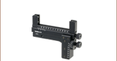
Application Idea
NDL-10C-4 Variable ND Filter Held
in an XYF1 Translating Filter Mount
(XYF1 Maximum Filter Width: 76.2 mm)

Please Wait
| Variable ND Selection Guide | ||||||
|---|---|---|---|---|---|---|
| Image |  |
 |
 |
 |
 |
 |
| ND Filter Type |
Round Step | Round Continuous |
Cage Compatible |
Rectangular Step |
Rectangular Continuous |
Variable Absorptive ND Filter |
Features
- Provides Continuously Variable Attenuation
- OD Ranges from 0.04 - 2.0 or 0.04 - 4.0
- Two Size Options
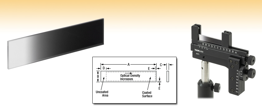
These rectangular, continuously variable reflective neutral density filters provide linear, adjustable attenuation within the coated region via translation. Offered in 10 mm x 50 mm and 25 mm x 100 mm sizes (H x W), these rectangular neutral density filters are available with OD ranges of either 0.04 - 2.0 or 0.04 - 4.0. Please refer to the Specs tab for more information. They are composed of a UV fused silica glass substrate and a metallic Inconel coating. The UV fused silica substrate used in these filters exhibits high transmission and virtually no laser-induced fluorescence (as measured at 193 nm), making it an ideal choice for applications from the UV to the near IR. While the spectral range's lower limit of 240 nm is limited by the absorption of the light by the substrate, UV fused silica provides good transmission up to 2.1 µm, and thus the upper limit of 1200 nm is dependent on the increased opacity of the Inconel coating. The optical density (OD) for each filter is specified at the design wavelength of 633 nm; some variation in the OD will occur over the usable range. The OD increases linearly from the start of the coating.
Optical density (OD) indicates the attenuation factor provided by an optical filter, i.e. how much it reduces the optical power of an incident beam. OD is related to the transmission, T, by the equation
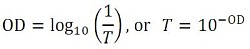
where T is a value between 0 and 1. Choosing an ND filter with a higher optical density will translate to lower transmission and greater reflection of the incident light. For higher transmission and less reflection, a lower optical density would be appropriate. As an example, if a filter with an OD of 2 results in a transmission value of 0.01, this means the filter attenuates the beam to 1% of the incident power. Please note that the transmission data for our neutral density filters is provided in percent (%). See the Graph tab for a plot of transmission as a function of distance when using one of our continuously variable filters.
Inconel is a metallic alloy that ensures flat spectral response from the UV to the near IR. Unprotected metal coatings like this should only be cleaned by blown air, never touched, as contact may cause scratching to the unprotected surface. Although these are reflective ND filters, the Inconel coating does absorb some of the incident light, which limits the use of these filters to low-power applications. Inconel is resistant to aging under normal conditions; however, it will oxidize at elevated temperatures. To prevent oxidation, Thorlabs recommends using these ND filters at temperatures below 100°C. To achieve the best performance light should be incident on the side with the Inconel coating.
For mounting options, the NDL-10C-2 and NDL-10C-4 can be mounted using the XYF1(/M) XY translation filter mount. Please note that a portion of the filter's edges will be covered when held between the two mounting arms.
These filters are not intended to serve as laser safety equipment. For lab safety, Thorlabs offers an extensive line of safety and blackout products that significantly reduces exposure to stray or reflected light.
| Common Specifications | |
|---|---|
| Substrate Material | UV Fused Silicaa |
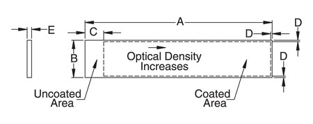
| Length Tolerance (A & B) | +0.00 / -0.25 mm |
| Coating Tolerance (C & D) | ±0.25 mm |
| Coating | Front: Inconel (NiCrFe) Back: Uncoated |
| Spectral Range | 240 - 1200 nm |
| Surface Flatness (@633 nm) | 1λ per 25 mm |
| Surface Quality | 60-40 Scratch-Dig |
| Wedge | <3 arcmin |
Item Specifications
| Item # | Optical Density Rangea | A | B | C | D | E |
|---|---|---|---|---|---|---|
| NDL-10C-2 | 0.04 - 2.0 | 50 mm | 10 mm | 2 mm | 5 mm | 1 mm |
| NDL-10C-4 | 0.04 - 4.0 | 50 mm | 10 mm | 2 mm | 5 mm | 1 mm |
| NDL-25C-2 | 0.04 - 2.0 | 100 mm | 25 mm | 2 mm | 10 mm | 2 mm |
| NDL-25C-4 | 0.04 - 4.0 | 100 mm | 25 mm | 2 mm | 10 mm | 2 mm |
The plot indicates the optical density and transmission as a function of distance from the end of the neutral density filter (i.e., length A as indicated in the diagram). Optical density and transmission are specified at 635 nm. Click here to download the raw OD and transmission data, which is theoretically calculated.
| Posted Comments: | |
user
(posted 2025-11-06 11:43:37.81) How does the OD vary at a wavelength of 365 nm (UV)? tdevkota
(posted 2025-11-07 09:47:45.0) Thank you for contacting Thorlabs. The OD increases linearly from the start of the coating. I have reached out to you directly to share the relevant data we have on hand. Ben Urban
(posted 2025-05-07 11:35:22.57) Does the incident light not transmitted get absorbed or reflected? jdelia
(posted 2025-05-07 01:22:40.0) Thank you for contacting Thorlabs. The NDL-10C-2 is a reflective neutral density filter. That said, the Inconel coating will still absorb some of the incident light. Eva Roche
(posted 2024-09-06 10:55:46.527) Good morning
I am Eva Roche, a researcher at the University of Zaragoza. I am interested in Continuously Variable Density Filters to work with a continuous 500mW laser (DPL) with a diameter of about 700um. We would like to know if you have any filters that are not damaged by this amount of mW.
Thank you for your attention
Best regards jpolaris
(posted 2024-09-06 07:06:35.0) Thank you for contacting Thorlabs. At this time we do not have comprehensive LIDT data for these continuously variable reflective ND filters. However, as a guideline, we found it best to keep the CW irradiance under 25 W/cm^2 for a Ø1 mm beam at 532 nm. You can calculate an LIDT adjusted to your wavelength by taking (LIDT Power)*((Your Wavelength)/(LIDT Wavelength)). In this case, LIDT Power would be 25 W/cm^2, and LIDT Wavelength would be 532 nm. I calculate your irradiance to be ~130 W/cm^2, which would be too powerful for these continuously variable reflective ND filters. Possibly somewhat counterintuitively, absorptive ND filters generally will have higher LIDT than reflective ND filters. For CW sources, we present LIDT in terms of linear power density [W/cm]. I calculate your uniform linear power density to be ~7.2 W/cm, and your Gaussian linear power density to be ~14.3 W/cm. We do have some absorptive ND filters that can withstand your source. The following link will take you to our selection of absorptive ND filters. If you require a variable absorptive ND filter, search the part number NEV0830M. https://www.thorlabs.com/newgrouppage9.cfm?objectgroup_id=5011 Madhavi Thakre
(posted 2024-04-09 17:40:17.957) Kindly provide the OD data and reflectance data also over a wavelength range of 240 - 1200 nm, other than the design wavelength (633 nm). jdelia
(posted 2024-04-11 02:21:55.0) Thank you for contacting Thorlabs. I have reached out to you directly to discuss your application and share the relevant data we have on hand. Thomas Dreischer
(posted 2023-02-21 13:52:14.78) We would need such a variable ND filter, but in the 1550 nm band (“C band”)
Could this be done?
Kind regards,
Thomas Dreischer cdolbashian
(posted 2023-04-03 01:56:29.0) Thank you for reaching out to us with this inquiry! These variable filters use nominally the same coating as the line of single OD reflective ND filters. Although we don't have data for the continuous change for the whole range of this ND filter, likely you can interpolate the data from each singular Reflective ND filter from the main filter page. Luca Bau
(posted 2022-07-06 15:04:03.54) It is specified that the OD will vary over the usable range. Do you happen to have data for wavelengths, other than the design wavelength (633 nm), such that I could estimate the variation for my setup, as I use different wavelengths? ksosnowski
(posted 2022-07-08 03:29:46.0) Hello Luca, thanks for reaching out to Thorlabs. We have OD data for the filter at various wavelengths. We were unable to send an email to the address which you provided. If you wish to have a direct discussion with us, please reach out to your local tech support team at Europe@thorlabs.de Melanie Saayman
(posted 2022-03-02 02:13:38.49) I realize these filters are specified up to 1200 nm, but do you have some performance data up to 1700 nm? cdolbashian
(posted 2022-03-08 11:49:15.0) Thank you for reaching out to us Melanie. While we do not have data for all the values of the continuously varying OD that is a feature of this filter, I have sent you extended performance data for OD values of 0.1,0.2,0.3,0.4,0.6,1,1.3,2,3,4. Hopefully this data will be helpful to your application. Martha Salazar-Romero
(posted 2021-03-04 05:24:34.67) Which is the power damage threshold for the variable neutral density filter? YLohia
(posted 2021-03-12 04:03:00.0) Thank you for contacting Thorlabs. Unfortunately, we have not yet performed intensive damage threshold tests on these filters to be able to characterize this parameter. The variable filters used in these filter wheels are similar to the NDC series UVFS variable filters located here. https://www.thorlabs.com/newgrouppage9.cfm?objectgroup_id=1393&pn=NDC-100C-2#1389. The damage thresholds recorded on this webpage will be mostly applicable for the NDL series filter wheels. felipe.hall
(posted 2018-12-28 13:50:48.883) The NDL-25C-2 has no simple way to mount it consistently to a motorized stage such as the MTS50-Z8. Using spring clips simply won't meet our application. Any plans on making something to meet this need? YLohia
(posted 2019-01-02 09:27:24.0) Hello, you may use the FP02 to mount the NDL-25C-2 to your MTS50-Z8. That being said, I have posted your request for a longer version of the XYF1 on our internal engineering forum. rbjaculbia
(posted 2018-07-01 22:53:00.11) Hi,
Which fixed mount do you recommend for these filters? Thanks! YLohia
(posted 2018-07-03 10:03:29.0) Thank you for contacting Thorlabs. We recommend the XYFM1 and many of the mounts on this page https://www.thorlabs.com/newgrouppage9.cfm?objectgroup_id=1446 dhseo
(posted 2017-08-24 08:15:04.917) I bought this filter to use my test. But it has a lot of reflection, so beam quality is lower. Can you add some extra AR coating at this filter? (I use 532 nm laser. So 532 nm AR coating is needed!!) I don't care it's price, if AR coating is possible. Please answer to my e-mail. Thnaks. tfrisch
(posted 2017-09-07 03:14:46.0) Hello, thank you for contacting Thorlabs. I will reach out to you to discuss a quote for the AR coated version. neil.troy
(posted 2014-07-30 16:12:00.063) Can you investigate creating a linear, in transmission, ND filter? The exponential transmission of these doesn't work well with our application. jlow
(posted 2014-08-07 03:04:48.0) Response from Jeremy at Thorlabs: Thank you for the suggestion. We are looking into carrying this in the future. We should be able to do a custom job for this at the moment. We will contact you directly to discuss about this. huarui.sun
(posted 2014-07-28 19:49:57.07) What's the thickness of the coating on NDL-25C-2? besembeson
(posted 2014-08-18 01:39:45.0) Response from Bweh at Thorlabs USA: This is a continuously variable neutral density filter hence the coating thickness varies across the structure to give the variable optical density (OD) or transmission. The coating is approximately 550 angstrom in the region with OD of 2. briggs1
(posted 2013-05-20 11:32:09.607) This product is almost perfect for what we're doing. I do have a question however. We're working with a Xenon flash lamp system and my advisor is worried about the grading degrading over time as we're operating at high energies (up to 20 J/cm2). How much of an issue do you see with the degradation of the inconel coating on the NDL-25C-4 graded NDF? cdaly
(posted 2013-05-22 16:34:00.0) Response from Chris at Thorlabs: Thank you for using our feedback tool. The damage threshold we specify for our ND filters is 0.025J/cm^2. I'm afraid you would be well over this limit. antoine.monmayrant
(posted 2013-03-05 09:40:51.0) Could you also give us the reflectivity for these densities? jlow
(posted 2013-03-07 11:29:00.0) Response from Jeremy at Thorlabs: You can find the reflectivity plots for the various OD at http://www.thorlabs.com/newgrouppage9.cfm?objectgroup_id=5022 since this is the same type of coating. The graphs and data are located under the "Graphs" tab. mgrabowski
(posted 2013-02-11 10:49:01.303) I need the back of the substrate AR coated for 457 nm. Can these be provided with a coating on the back side? jlow
(posted 2013-02-14 14:45:00.0) Response from Jeremy at Thorlabs: We could possibly put the -A ARC on the back. I will e-mail you directly to start the quoting process. tcohen
(posted 2012-10-18 12:03:00.0) Response from Tim at Thorlabs: Although we do not yet have tested LIDT on this item, testing on similar coatings have shown that <25 W/cm^2 (1mm BD, 532nm) are recommended to prevent damage. However, because of the damage mechanism, power density does not perfectly scale with beam diameter. The power density can be higher for smaller beam diameters and I would like to discuss your setup in more depth. As the damage threshold is largely thermal, keeping below 100C is recommended. jvesel
(posted 2012-10-11 15:41:30.32) can these nd filter withstand input intensities of 3 to 4 watts/cm^2 from a broad band source such as a xenon lamp?
if necessary,cooling could be used to keep temperature down below 100 C bdada
(posted 2012-04-12 16:30:00.0) Response from Buki at Thorlabs:
Thank you for your feedback. These ND filters are designed for a spectral range of 240 to 1200nm. We will contact you to discuss other options. g9622513
(posted 2012-04-12 06:37:39.0) We require a linear variable Neutral-Density Filter for 2100 nm. Does this Continuously Variable Metallic Neutral Density Filter be used for 2100 nm? |