 Products Home
High-Power UV Curing LED System
- Customizable Exposure Times and Intensities
- User Calibration for Reproducible Exposure
- 4 Wavelength Options Available
- 5 Operation Modes
Source Stand
Included
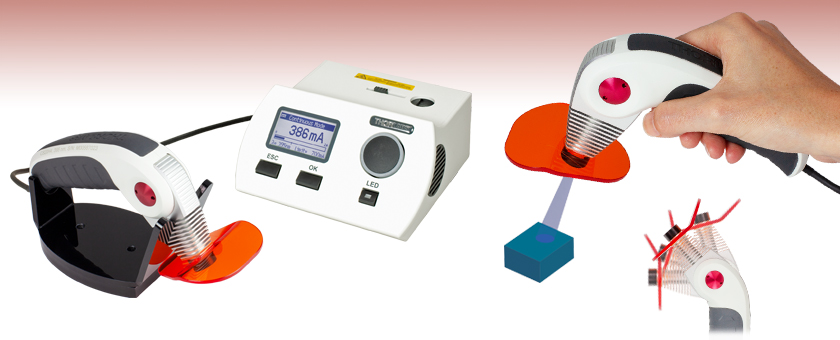
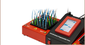
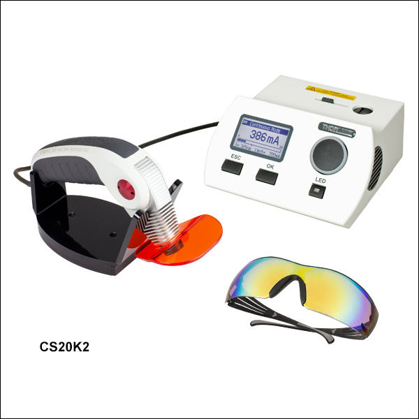
CS20K2
365 nm UV Curing System
with Driver Unit and
Handheld Light Source
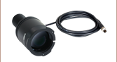
The Swiveling Mounted
Handheld LED Source
Includes a Removeable
UV Ray-Shield


Please Wait
 Click to Enlarge
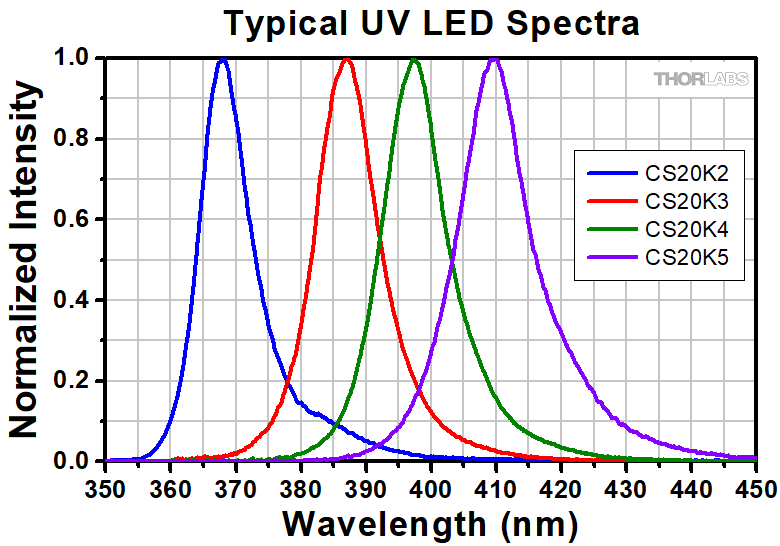
Figure 1.1 Typical Emission Spectra of the UV Curing LED Systems
Features
- ≥12 W/cm² LED Power Density at Center Wavelength*
- 365 nm, 385 nm, 395 nm, and 405 nm Systems Available
- Options for Adjusting Beam Spot Size and Shape
- Ø32 mm Beam at 20 mm Distance Without Optics
- Ø9 mm Collimated Beam Using Included CS20A2 Collimation Adapter
- Ø1 mm Focused Beam Using CS20A3 Focus Adapter (Sold Separately Below)
- User Calibration with Included Power Density Detector
- Operation Modes: Timer, Continuous, Configuration, Slope, or Irradiance
- 10 Configurable Measurement Profiles
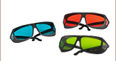
- Safety Glasses Included
- USB Port for PC Control
- Acoustic Time Signal
- Trigger Operation via Controller, Foot Switch, or Hand Trigger
Thorlabs' advanced UV Curing LED Systems are designed to cure adhesives that need to be exposed to reproducible high-intensity light at UV wavelengths. Complete systems are available with center wavelengths of 365 nm, 385 nm, 395 nm, and 405 nm. Five operation modes allow fine control of the duration and intensity of emission. Up to 10 different settings for intensity and exposure time can be stored in configuration profiles. The integrated power density detector enables calibration of the emission time based on the current power density of the LED.
Five Operation Modes
- Continuous Mode: The intensity of the emitted light can be continuously adjusted up to the user-set maximum current limit (by default, the absolute maximum of the chip). The intensity scale can be displayed as current in mA, % of maximum current, or the output irradiance (in mW/cm²).
- Timer Mode: This mode allows the user to limit the exposure time for a selected intensity.
- Slope Mode: This mode allows the user to gradually increase or decrease the intensity over a chosen time interval. Simply choose the initial and final intensities and the intensity will vary in a linear fashion during the chosen time period.
- Configuration Mode: 10 different user-defined timer mode profiles can be stored.
- Irradiance Mode: Use this mode to recalibrate all settings or to measure the irradiance of the LED source.
The integrated power density detector enables calibration of the emission time based on the current power density of the LED source. An acoustic signal can also be activated to generate beeps at determined time intervals. The output of the curing system is SM05-threaded; optics can be easily interchanged to produce different beam spot sizes and shapes.
Compared to conventional arc-lamp UV systems, these LED systems offer many advantages, such as an intense, uniform UV radiation profile and a long lifetime of 10 000+ hours. It requires much less energy, needs no warm-up time, and exhibits low IR heat emission. The system has no moving parts (passive, fan-less cooling) and is maintenance free. Additionally, the source contains no mercury and generates no ozone during the curing process.
Optical Accessories
See below for optical accessories for the UV Curing LED Systems. The beam diameter can be changed to 9 mm or 1 mm with the CS20A2 Collimation Adapter or CS20A3 Focus Adapter, respectively. One CS20A2 Collimation Adapter is included with each UV curing LED system. While the LED system can be used without an optic, the output light will diverge to 32 mm diameter measured 20 mm from the output.
Electrical Accessories
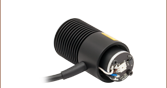
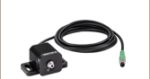
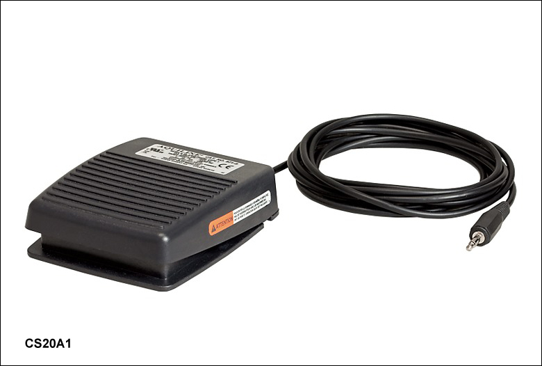
See below for electrical accessories for the UV Curing LED Systems. The CS20A1 Foot Switch is designed as an alternative means for turning the LED on and off without having to use the controller or software. The CAB-CS20 adapter cable allows the driver in any of our UV curing LED systems to be used to drive our mounted LEDs or fiber-coupled LEDs.
Safety Glasses
Safety glasses are recommended when using our UV Curing LED Systems. One pair is included with the purchase of a UV Curing LED system. In addition, Thorlabs offers several pairs of glasses that are appropriate for use with these systems. Please visit our Laser Safety Glasses page for detailed information about each of these items. Since the correct choice of laser safety eyewear depends upon many local factors that cannot be evaluated remotely, including the beam path, light source parameters, and lab environment, we recommend that you discuss your needs with your organization's laser safety officer to determine the best option.
*Calculated power density using CS20A3 Focus Adapter (sold separately below). The calculation is done using the minimum LED power. See the Specs tab for more information.
All specifications are valid at 23 ± 5 °C and 45 ± 15% relative humidity (non-condensing) unless otherwise noted.
| Common Specifications | |
|---|---|
| Operating Modes | |
| Continuous Mode | Power: 0% - 100% |
| Timer Mode | Power: 0% - 100% Time: 1 s - 2 h 46 min 39 s |
| Config Mode | 10 Configurations in Timer Mode |
| Slope Mode | Time: 1 s - 2 h 46 min 39 s Start Power: 0% - 100% Stop Power: 0% - 100% |
| LED | |
| LED Chip | 2.5 mm x 2.5 mm |
| Risk Groupa | RG2 |
| Beam Diameter | |
| Collimated using CS20A2b | 9 mm |
| Focused using CS20A3c | 1 mm |
| Divergent without Optics (Distance: 20 mm) |
32 mm |
| General | |
| Operating Temperature Ranged | 0 to 40 °C |
| Storage Temperature Range | -40 to 70 °C |
| Main Unit Dimensions (W x H x D) |
157 mm x 80 mm x 158 mm (6.2" x 3.2" x 6.2") |
| Hand Held Unit Dimensions (W x H x D) |
95 mm x 180 mm x 32 mm (3.6" x 7.1" x 1.3") |
| Warm Up Time for Rated Accuracy | <10 min |
| Weight | <1 kg |
| Item # | CS20K2 | CS20K3 | CS20K4 | CS20K5 |
|---|---|---|---|---|
| Optical Properties | ||||
| Wavelength | 365 nm | 385 nm | 395 nm | 405 nm |
| UV LED Power | 880 mW (Min) 1290 mW (Typical) |
1240 mW (Min) 1780 mW (Typical) |
1130 mW (Min) 1630 mW (Typical) |
748 mW (Min) 1082 mW (Typical) |
| Irradiance | ||||
| Collimated using CS20A2a | 178 mW/cm2 (Min) | 194 mW/cm2 (Min) | 185 mW/cm2 (Min) | 164 mW/cm2 (Min) |
| Focused using CS20A3b | 13 W/cm2 (Min) | 14 W/cm2 (Min) | 13 W/cm2 (Min) | 12 W/cm2 (Min) |
| Divergent without Optics (20 mm from LED Chip) |
56 mW/cm2 (Min) | 76 mW/cm2 (Min) | 72 mW/cm2 (Min) | 61 mW/cm2 (Min) |
 Click to Enlarge
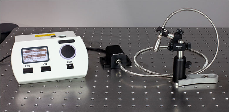 Click to Enlarge
| Driver Unit Operating Specifications | |
|---|---|
| Maximum Voltage | 20 V |
| Maximum Current | 2 A |
The CAB-CS20 adapter cable (sold separately below), allows the driver unit of Thorlabs UV curing systems to drive any Thorlabs mounted LED or fiber-coupled LED. This flexibility enables our UV curing systems to be adapted for use in more stable or space-constrained setups using our complete families of optomechanical components, fiber patch cables, and fiber optomechanics. We also offer a much broader wavelength selection from deep UV to NIR for both our mounted LEDs and our fiber-coupled LEDs, down to as low as 265 nm and 285 nm, respectively.
Using Driver Unit with Thorlabs Mounted LEDs
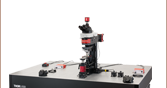
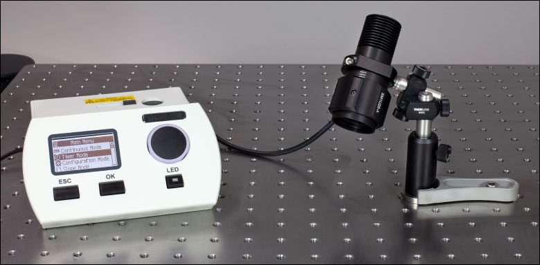
For applications that require high power and stability, any Thorlabs mounted LED can be connected using the CAB-CS20 adapter cable to the driver unit of the CS20K2, CS20K3, CS20K4, or CS20K5. The LED can be mounted using standard optomechanical components as shown in Figure 3.1. The parts list is given as an example and can easily be adapted for the space and stability constraints of any particular setup. Please contact Tech Support for help on selecting the appropriate items for a specific application.
Using Driver Unit with Thorlabs Fiber-Coupled LEDs
For curing applications with space constraints, a fiber-coupled LED can be connected using the CAB-CS20 adapter cable to the driver unit of the CS20K2, CS20K3, CS20K4, or CS20K5. The LED can be mounted using standard optomechanical components as shown in Figure 3.2. We also offer a wide range of fiber collimators to ensure the output is suitable for curing applications. The parts list is given as an example and can easily be adapted for the space and stability constraints of any particular setup. Please contact Tech Support for help on selecting the appropriate items for a specific application.
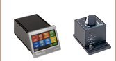
Software for High-Power UV Curing LED Systems
Software
Version 1.0
Standard full software application packages and graphical user interfaces.
| Posted Comments: | |
Robert Quinton
(posted 2025-03-14 10:52:48.95) We have a few of your CS20K2 guns and need to know how to do a PM or CAL and frequency of that and is there equipment/tools to verify their operation and functionality? jjadvani
(posted 2025-03-17 08:20:34.0) Dear Robert, Thank you for contacting Thorlabs. If you look at the manual by clicking on the following link (https://www.thorlabs.com/_sd.cfm?fileName=MTN021873-D02.pdf&partNumber=CS20K2 ), on page 9 you will discover the process for recalibration. I'll contact you directly to provide more details. M H
(posted 2024-01-18 08:53:38.117) Hello,
I have a question regarding the UV Curing LED System with 365 nm wavelength (product name: CS20K2). Is it possible to purchase only the driver unit of this UV Curing LED System (meaning without the handheld light source)? If it is possible, what would be price for only the driver unit and how long would be the lead time and the shipping costs to Germany? fmortaheb
(posted 2024-01-18 09:27:57.0) Thank you very much for your inquiry. We can offer you the driver, separately. I'll reach out to you directly to provide you with further information. Tero Kumpulainen
(posted 2022-10-03 16:11:15.527) Hi,
Are you planning to add different wavelenght available in the future? We are looking for a 450nm curing system. fmortaheb
(posted 2022-10-05 07:58:01.0) Thank you very much for contacting us. Currently, there is no plan to add new wavelengths for this product in the near future. I'll contact you directly to discuss your application. f beh
(posted 2019-06-18 11:25:55.42) Hi,
Is it possible to use other LED with wavelenght of 390 nm ? MKiess
(posted 2019-06-19 06:33:48.0) This is a response from Michael at Thorlabs. Thank you very much for your inquiry. We may be able to offer such a custom version of the CS2010. I will contact you directly to discuss your requirements. William Lowry
(posted 2019-05-09 14:06:20.453) Both the housing and the power adapter for the DC2100 look identical to the housing and power adapter for the CS2010, however, if the adapter for the DC2100 is plugged into the CS2010, it will overload and destroy the circuit card assembly. If possible, perhaps a different interface could be used in order to avoid the wrong power cable from being plugged in. dpossin
(posted 2019-06-06 09:46:24.0) Hello, thank you for your feedback. As we take concerns like this very serious, I checked the number of RMAs created by wrong plugged power supplies and just found one case. Due to this and the fact that the DC2100 is already obsolete we do not think that there is high potential of failure. rpompano
(posted 2018-12-18 23:13:45.28) Hello, is it possible to obtain this unit with a 395 or 405 nm LED instead of a 365 nm LED? That would be useful for use with certain biomaterials. Thank you. wskopalik
(posted 2018-12-20 11:21:52.0) This is a response from Wolfgang at Thorlabs. Thank you very much for your inquiry.
We are possibly able to offer such a custom version of the CS2010. I will contact you directly to discuss your requirements. aseerboss
(posted 2018-07-24 18:47:44.7) Hello,
I would like to know if the intensity of the light is constant across the entire exposure area.
For the application that I want, the exposure has to be uniform, so I would like to know if there would be any variations across the exposed area.
Thanks ^^ swick
(posted 2018-08-08 04:46:32.0) This is a response from Sebastian at Thorlabs. Thank you for the inquiry.
The UV light from the CS2010 is generated by a LED followed by an optical diffuser for homogenization.
The spatial power distribution is non-constant over the entire beam diameter.
The intensity decrease to the sides of the beam thus the most constant irradiance will be in the center. I contacted you directly for discussion. matandudaie
(posted 2018-07-09 00:22:43.657) hi, i want to use your product with less power, so i want to put it at a bigger distance. i just couldn't figure which. the manual says at a distance of 20mm the power gets down from 27 W/cm^2 to 25mW/cm^2. but i could not calculate it from the data (the divergance of 30mm is not clear enough)
what is the angle of divergance?
* i want it to be around 0.7mW/cm^2
thanks swick
(posted 2018-07-20 03:59:21.0) This is a response from Sebastian at Thorlabs. Thank you for the inquiry.
We specify the beam diameter (divergent without optics) at distance 20 mm to be 30 mm. The dimension of the LED chip is 1 mm x 1 mm. The resulting divergence is approx 36 ° (half-angle). lebouquj
(posted 2018-07-02 11:02:47.137) Hi, do you have the manual for the (now discontinued) Thorlabs 560 UV75 40mW ? Many thanks, Jean-Baptiste wskopalik
(posted 2018-07-04 10:40:49.0) This is a response from Wolfgang at Thorlabs. Thank you very much for your feedback!
This UV curing system was discontinued more than 10 years ago, but I will check if we still have a file or a copy of this manual.
I will contact you directly. dvance
(posted 2018-06-18 15:44:56.157) We set our CS2010 for 150mW/cm^2 but after a week's use it will no longer adjust above 142mW. Is this normal? swick
(posted 2018-07-11 05:38:53.0) This is a response from Sebastian at Thorlabs. Thank you for the inquiry.
The power density displayed on the CS2010 corresponds to the irradiance in an 8mm distance from the LED without optics (equal to 5mm from the front of the handset). This value is different to the optical parameters we specify. In case the optical power degrades further in the next weeks we would like to inspect the device. I contacted you directly for further assistance. jv
(posted 2018-04-18 12:52:46.53) Just a note that the listed spec of 27W/cm^2 is a little misleading since that power density is not what the user gets. Would be more helpful to highlight the actual power density the user would get at a particular distance from the lens. This would be closer to the 150mW/cm^2 value... but at what distance? Distance with a lens is not in the specs.
JV swick
(posted 2018-05-04 04:17:51.0) This is a response from Sebastian at Thorlabs. Thank you for the feedback.
When using CS20A3 the power density 10 W/cm² (Min) is specified at the working distance which is 6.1 mm from the lens. The power density of 150 mW/cm² (Min) is stated for the collimated beam of 12 mm when using CS20A2. cpinyan
(posted 2017-06-21 10:49:02.627) it beeps every 10 seconds while running. It would be nice if the "time is up" beep was longer or different in some way. I have 3 running at different starting points, nice to know that one is done. wskopalik
(posted 2017-06-22 05:43:29.0) This is a response from Wolfgang at Thorlabs. Thank you very much for your feedback!
I have forwarded it to our R&D department so they can consider it the next time changes are made on the firmware.
I will also contact you directly to discuss this in further detail. acable
(posted 2017-01-15 14:11:37.23) How do I mount the head within my setup. You provide a drawing of the driver but no details are given on the head. wskopalik
(posted 2017-01-16 05:29:54.0) This is a response from Wolfgang at Thorlabs. Thank you for your feedback!
The head of the CS2010 is primarily designed as a handheld device. It is however possible to mount the head by using the SM05 threading at the output.
When the head is used with the collimation adapter CS20A2 or without an adapter, the SM05 threading can be used directly to attach the head to a mount. When the focus adapter CS20A3 is installed on the head, the threading isn't accessable any more. In this case you can e.g. use a lens tube slip ring SM05RC to mount the head.
I have contacted you directly to discuss this in further detail. rpscott
(posted 2013-06-06 14:15:48.297) Your webpage says, "the beam diameter can be changed to 12 mm or 1 mm with the CS20A2 Collimation and CS20A3 Focus Adapter, respectively. The latter is included with the purchase of the UV curing system." However, pg. 30 of the manual says that the CS20A3 is NOT included in the base system. Can you please confirm which is correct? tschalk
(posted 2013-06-10 05:18:00.0) This is a response from Thomas at Thorlabs. Thank you very much for your inquiry. The focus adapter CS203A is not included in the CS2010. It is an additional part which can be purchased separately. You can find a part list in the manual (http://www.thorlabs.de/Thorcat/22100/CS2010-Manual.pdf, 2.1 Parts List), there you can see that only the collimation adapter CS20A2 is included. sayapple11
(posted 2013-01-18 12:54:05.867) We use this product useful. So we always satisfied it.
The one thing I wonder is whether wavelength is 365nm or 360nm.
Spces are indicated that wavelength is 360nm. However name of products are indicated that wavelength is 365nm. So I want to know what wavelength is exact.
wait your response.
Thank you. jvigroux
(posted 2013-01-18 08:16:00.0) A response from Julien at Thorlabs: Thank you for your feedback! I am glad you are satisfied with this product. Concerning the wavelength in the specification table, this is a mistake. The central wavelength of the LED is 365nm. We will correct this error immediately. |

 Zoom
Zoom| Key Specificationsa | |||||
|---|---|---|---|---|---|
| Item # | Wavelength | Power | Irradiance (without Optics)b | Beam Diameter (without Optics)b | Risk Groupc |
| CS20K2 | 365 nm | 880 mW (Min) | 56 mW/cm2 (Min) | 32 mm | RG2 |
| CS20K3 | 385 nm | 1240 mW (Min) | 76 mW/cm2 (Min) | ||
| CS20K4 | 395 nm | 1130 mW (Min) | 72 mW/cm2 (Min) | ||
| CS20K5 | 405 nm | 748 mW (Min) | 61 mW/cm2 (Min) | ||
| Item # | CS20A2a,b | CS20A3b |
|---|---|---|
| Click on the Image to Enlarge |
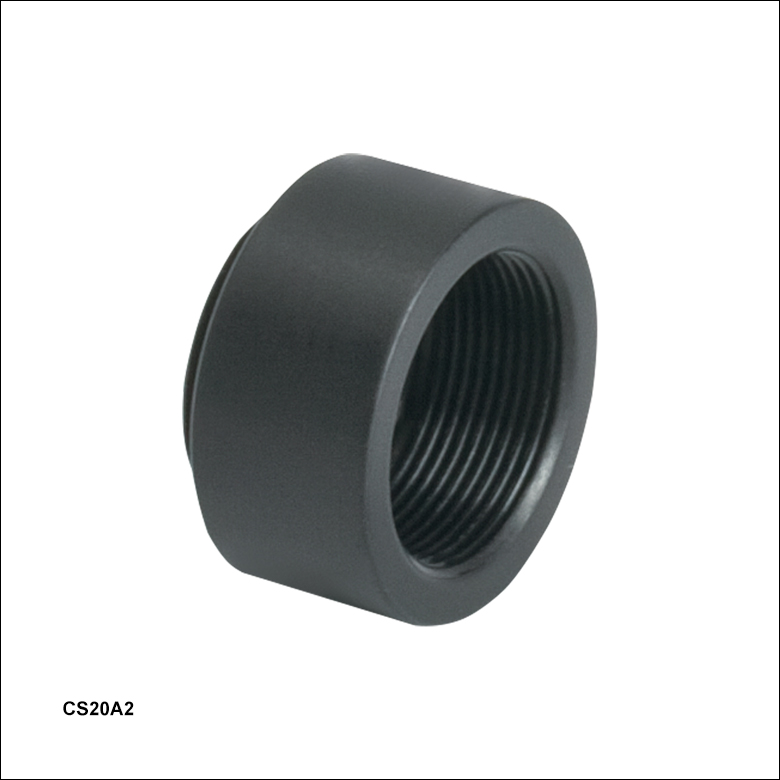 |
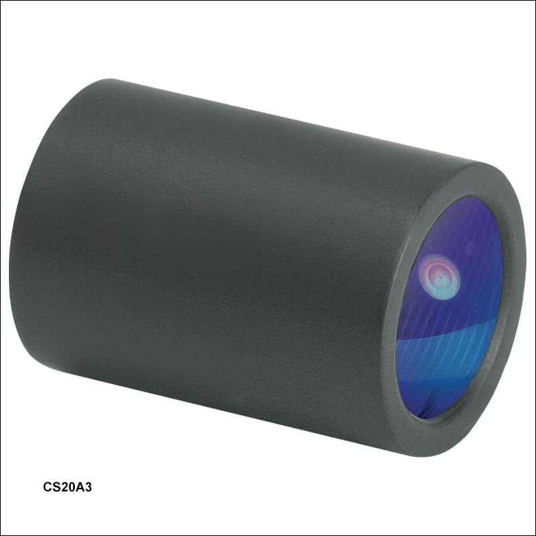 |
| Description | Collimation Adapter | Focus Adapter |
| Beam Diameter of UV Curing System with Optic | 9 mm | 1 mm |
| Irradiance Output of UV Curing Systems with Optical Accessories | ||
| CS20K2 | 178 mW/cm2 (Min) | 13 W/cm2 (Min) |
| CS20K3 | 194 mW/cm2 (Min) | 14 W/cm2 (Min) |
| CS20K4 | 185 mW/cm2 (Min) | 13 W/cm2 (Min) |
| CS20K5 | 164 mW/cm2 (Min) | 12 W/cm2 (Min) |
| Item # | CS20A1a | CAB-CS20 |
|---|---|---|
| Click on the Image to Enlarge |
 |
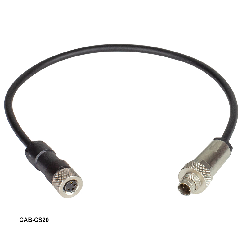 |
| Description | Foot Switch | Adapter Cable for Mounted and Fiber-Coupled LEDsb |
| Cable Length | 2 m | 250 mm ± 10 mm |
| Connector Type(s) | 3.5 mm Phono Jack | 7-Pin and 4-Pin (See Table G3.1) |
| Table G3.1 CAB-CS20 Connector Pin-Out | ||
|---|---|---|
| Driver Unit Side Pin # | Description | LED Side Pin # |
| 1 | GND | 3 |
| 2 | I/O EEPROM | 4 |
| 3 | Not Connected | N/A |
| 4 | Not Connected | N/A |
| 5 | Not Connected | N/A |
| 6 | LED - | 2 |
| 7 | LED + | 1 |