 Products Home / Polarization Optics / Polarizers / Crystal Polarizers / alpha-BBO Glan-Laser Polarizers
alpha-BBO Glan-Laser Polarizers
- Designed for High-Power Laser Applications
- Extinction Ratio: 100,000:1
- Laser Quality α-BBO Crystal
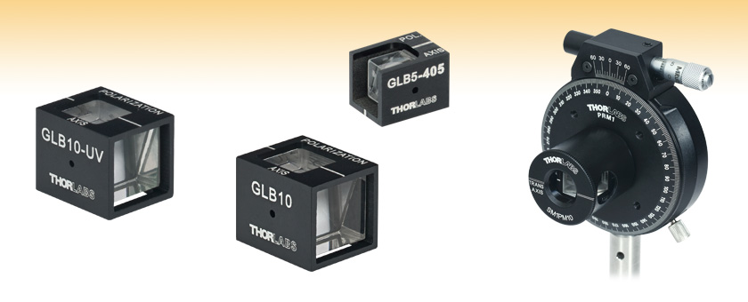
GLB10-UV
GLB10
GLB5-405
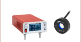
GLB10 Polarizer and
SM1PM10 Mount on a
PRM1 Rotation Mount


Please Wait
Alpha-BBO Glan-Laser Polarizers Divert Ordinary Rays, Leaving Highly Polarized Extraordinary Rays (Aligned with the "Polarization Axis" Mark on the Housing) Passing Through the Polarizer

Features
- Extinction Ratio for Output Beam: 100,000:1
- Fabricated from the Highest-Grade, Laser-Quality α-BBO
- Three Available Coatings
- 210 - 450 nm (centered at 266 nm), Ravg < 1.5%
- 220 - 370 nm, Ravg < 0.5%
- VAR for 405 nm, Ravg < 0.25%
- High Damage Threshold: 5 J/cm2 (10 ns pulse, 10 Hz, Ø0.347 mm Spot Size, @ 355 nm)
- Low Scatter
- Wavefront Distortion ≤ λ/8 Over Clear Aperture (Excluding Side Ports)
- Surface Quality
- 20-10 Scratch-Dig on AR-Coated Input and Exit Faces
- 40-20 Scratch-Dig on Uncoated Side Ports
- Glan-Taylor Design (Air-Spaced Birefringent Crystal Prisms)
Our Glan-Laser α-BBO Polarizers are specifically designed to deal with high-energy, short-wavelength laser light. Like our Glan-Taylor and Glan-Laser Calcite Polarizers, these polarizers are ideal for applications requiring extremely high polarization purity (100,000:1), high damage threshold (5 J/cm2, 10 ns pulse, 10 Hz, 0.347 mm Spot Size, @ 355 nm), and transmisison in the UV (210 - 450 nm). A significant amount of reflected light escapes the polarizers through the side port, including all of the ordinary ray and some of the extraordinary ray. As such, the escape beam is not fully polarized, and only the transmitted extraordinary ray should be used for applications that require a high-quality, polarized beam.
The input and output faces of these polarizers are polished to a laser quality 20-10 scratch-dig surface finish to minimize scattering of the transmitted extraordinary polarization component of the incident laser beam or light field. The ordinary polarization component is reflected and exits the polarizer at a 61° angle (wavelength dependent) through one of the two uncoated side ports, which are provided to allow bidirectional use of the polarizer. The escape ray is not fully polarized and the side escape ports have a lower surface quality of 40-20 scratch-dig. In addition, the hygroscopic nature of α-BBO may cause these uncoated side faces may become hazy over time as the crystal absorbs water from the air, further decreasing the beam quality of the escape ray.
The polarizers are available with three antireflection coatings: a single-layer MgF2 antireflection coating (SLAR-MgF2), a UV AR coating, or a V Coating optimized for 405 nm. The SLAR coating features good broadband UV performance with low reflectance (<1.5%) from 210 to 450 nm while the UV AR coating provides exceptionally low reflectance (<0.5%) from 220 to 370 nm. The 405 nm V coating provides even less reflectance (<0.25%) than the UV coating at 405 nm. These coatings also serve as a protective layer that prevents the hygroscopic α-BBO substrate from interacting with moisture in the environment. Please see the Graphs tab for more information about the reflectance of these coatings.
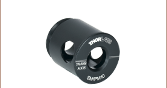
For compatibility with Thorlabs' selection of rotation mounts and other optomechanics, these polarizers can be mounted in our Polarizing Prism Mounts, which are available for both 5 mm (SM05PM5) and 10 mm polarizers (SM1PM10). Thorlabs also provides Glan-Taylor polarizers.
| Item # | GLB5 | GLB10 |
|---|---|---|
| Extinction Ratioa | 100,000:1 | |
| Substrate | Laser Quality α-BBOb (Low Scatter) |
|
| Design | High Laser Damage Threshold Air-Spaced Design |
|
| Transmission Range | 210 - 450 nm | |
| Available AR Coatingsc | SLAR MgF2 (210 - 450 nm), Ravg< 1.5% UV (220 - 370 nm), Ravg< 0.5% V-Coat (405 nm), Ravg< 0.25% |
|
| Damage Thresholdd | 5 J/cm2 (10 Hz, Ø0.347 mm Spot Size, 10 ns Pulses @ 355 nm) | |
| Wavefront Distortion | ≤ λ/8 Over Clear Aperture | |
| Surface Quality (Input and Output Faces) | 20/10 Scratch/Dig | |
| Surface Quality (Side Ports) | 40/20 Scratch/Dig | |
| Clear Apertured | 5 mm x 5 mm | 10 mm x 10 mm |
| Prism Dimensions (W x L) | 6.5 mm x 7.5 mm | 12 mm x 13.7 mm |
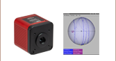
Field of View Angle Orientation
A significant amount of scattered unpolarized light escapes the polarizers. As a result, the escape ray (o-ray) is not purely polarized and should not be used for polarization dependent applications.
The typical transmission and reflectivity of the α-BBO Glan-Laser polarizers are shown in the graphs below. The blue shading indicates the region for which the AR coating is optimized (see Specs tab for more information). The reflectivity plots represent the performance of the coating only, not including internal losses of the polarizer. The transmission plots include both both reflectivity and transmission through the polarizer (including any internal losses).
The plots below apply to the GLB10 and GLB5 α-BBO Glan-Laser polarizers.
The plots below apply to the GLB10-UV and GLB5-UV α-BBO Glan-Laser polarizers.

The plots below apply to the GLB10-405 and GLB5-405 α-BBO Glan-Laser polarizers.
Note: Short wavelength cutoff is due to the cut angle of the α-BBO prism, not the reflectivity or transmission of the material.
Glan Laser Specifications
| Item # | GLB5 | GLB10 |
|---|---|---|
| W | 6.5 mm | 12 mm |
| La | 7.5 mm | 13.7 mm |
| A | 9.5 mm | 16 mm |
| B | 12.7 mm | 19.2 mm |
Polarization-Dependent Refraction - Glan Laser α-BBO Polarizer
General
Thorlabs' α-BBO polarizers are all based on high-grade, birefringent α-BBO crystals. Due to the birefringent nature of α-BBO, waves polarized in the direction of the optical axis propagate with a different index of refraction than waves polarized orthogonally to the optical axis. In our Glan-Laser polarizers, this birefringence causes the ordinary polarization component of an incident beam to undergo total internal reflection at an internal glass-to-air interface. The light transmitted through the polarizer then consists of only the remaining extraordinary polarization component. While these transmitted extraordinary rays are highly polarized, the reflected ordinary rays are only partially polarized.
Our Glan-Laser and Glan-Taylor polarizer are designed as polarizer elements that remove the reflected ordinary polarization component of a beam. These polarizers are built out of two prisms, as shown in the drawing to the right. They are only designed to work with well collimated light beams; converging and diverging input beams will not exhibit proper polarization and incidence angle at the internal interface. Since α-BBO is a soft crystal that is easily damaged, all of our α-BBO polarizers are offered in metal housings. With convenient threadings and adapters, these housings can easily be mounted into our opto-mechanical products.
Field of View
α-BBO polarizers feature a field of view (FOV) that varies with both wavelength and entrance orientation. The FOV of these prisms must be considered during alignment and collimation procedures. The side of the polarizer with the escape window has an FOV that decreases with increasing wavelength (FOV 1). The opposite side has an FOV that increases at longer wavelengths (FOV 2).
Field of View Angle Orientation
Transmission
Thorlabs uses only the highest quality synthetic α-BBO in our polarizing prisms. The transmission curves of the α-BBO polarizers are shown on the Overview tab. These curves also represent the transmission of the GLB5, GLB5-UV, and GLB5-405. Variations during the manufacturing of the α-BBO crystal affect the transmission curve and the damage threshold rating.
| Damage Threshold Specifications | |
|---|---|
| Item # | Damage Threshold |
| GLB5- GLB10- |
5 J/cm2 (10 Hz, Ø0.347 mm Spot Size, 10 ns Pulses @ 355 nm) |
Damage Threshold Data for Thorlabs' α-BBO Glan-Laser Polarizers
The specifications to the right are measured data for the coatings used in Thorlabs' α-BBO Glan-Laser polarizers.
Care should be taken to ensure that the polarizer's clear aperture is large enough for your beam, and that the polarizer is well aligned. While each polarizer is air-spaced within the clear aperture, the prisms composing the polarizer are separated by an epoxied photo-etched spacer that is not designed to withstand high laser powers. Using these parts outside of the clear aperture can result in catastrophic damage and failure.
Laser Induced Damage Threshold Tutorial
The following is a general overview of how laser induced damage thresholds are measured and how the values may be utilized in determining the appropriateness of an optic for a given application. When choosing optics, it is important to understand the Laser Induced Damage Threshold (LIDT) of the optics being used. The LIDT for an optic greatly depends on the type of laser you are using. Continuous wave (CW) lasers typically cause damage from thermal effects (absorption either in the coating or in the substrate). Pulsed lasers, on the other hand, often strip electrons from the lattice structure of an optic before causing thermal damage. Note that the guideline presented here assumes room temperature operation and optics in new condition (i.e., within scratch-dig spec, surface free of contamination, etc.). Because dust or other particles on the surface of an optic can cause damage at lower thresholds, we recommend keeping surfaces clean and free of debris. For more information on cleaning optics, please see our Optics Cleaning tutorial.
Testing Method
Thorlabs' LIDT testing is done in compliance with ISO/DIS 11254 and ISO 21254 specifications.
First, a low-power/energy beam is directed to the optic under test. The optic is exposed in 10 locations to this laser beam for 30 seconds (CW) or for a number of pulses (pulse repetition frequency specified). After exposure, the optic is examined by a microscope (~100X magnification) for any visible damage. The number of locations that are damaged at a particular power/energy level is recorded. Next, the power/energy is either increased or decreased and the optic is exposed at 10 new locations. This process is repeated until damage is observed. The damage threshold is then assigned to be the highest power/energy that the optic can withstand without causing damage. A histogram such as that below represents the testing of one BB1-E02 mirror.
The photograph above is a protected aluminum-coated mirror after LIDT testing. In this particular test, it handled 0.43 J/cm2 (1064 nm, 10 ns pulse, 10 Hz, Ø1.000 mm) before damage.
| Example Test Data | |||
|---|---|---|---|
| Fluence | # of Tested Locations | Locations with Damage | Locations Without Damage |
| 1.50 J/cm2 | 10 | 0 | 10 |
| 1.75 J/cm2 | 10 | 0 | 10 |
| 2.00 J/cm2 | 10 | 0 | 10 |
| 2.25 J/cm2 | 10 | 1 | 9 |
| 3.00 J/cm2 | 10 | 1 | 9 |
| 5.00 J/cm2 | 10 | 9 | 1 |
According to the test, the damage threshold of the mirror was 2.00 J/cm2 (532 nm, 10 ns pulse, 10 Hz, Ø0.803 mm). Please keep in mind that these tests are performed on clean optics, as dirt and contamination can significantly lower the damage threshold of a component. While the test results are only representative of one coating run, Thorlabs specifies damage threshold values that account for coating variances.
Continuous Wave and Long-Pulse Lasers
When an optic is damaged by a continuous wave (CW) laser, it is usually due to the melting of the surface as a result of absorbing the laser's energy or damage to the optical coating (antireflection) [1]. Pulsed lasers with pulse lengths longer than 1 µs can be treated as CW lasers for LIDT discussions.
When pulse lengths are between 1 ns and 1 µs, laser-induced damage can occur either because of absorption or a dielectric breakdown (therefore, a user must check both CW and pulsed LIDT). Absorption is either due to an intrinsic property of the optic or due to surface irregularities; thus LIDT values are only valid for optics meeting or exceeding the surface quality specifications given by a manufacturer. While many optics can handle high power CW lasers, cemented (e.g., achromatic doublets) or highly absorptive (e.g., ND filters) optics tend to have lower CW damage thresholds. These lower thresholds are due to absorption or scattering in the cement or metal coating.
LIDT in linear power density vs. pulse length and spot size. For long pulses to CW, linear power density becomes a constant with spot size. This graph was obtained from [1].
Pulsed lasers with high pulse repetition frequencies (PRF) may behave similarly to CW beams. Unfortunately, this is highly dependent on factors such as absorption and thermal diffusivity, so there is no reliable method for determining when a high PRF laser will damage an optic due to thermal effects. For beams with a high PRF both the average and peak powers must be compared to the equivalent CW power. Additionally, for highly transparent materials, there is little to no drop in the LIDT with increasing PRF.
In order to use the specified CW damage threshold of an optic, it is necessary to know the following:
- Wavelength of your laser
- Beam diameter of your beam (1/e2)
- Approximate intensity profile of your beam (e.g., Gaussian)
- Linear power density of your beam (total power divided by 1/e2 beam diameter)
Thorlabs expresses LIDT for CW lasers as a linear power density measured in W/cm. In this regime, the LIDT given as a linear power density can be applied to any beam diameter; one does not need to compute an adjusted LIDT to adjust for changes in spot size, as demonstrated by the graph to the right. Average linear power density can be calculated using the equation below.
The calculation above assumes a uniform beam intensity profile. You must now consider hotspots in the beam or other non-uniform intensity profiles and roughly calculate a maximum power density. For reference, a Gaussian beam typically has a maximum power density that is twice that of the uniform beam (see lower right).
Now compare the maximum power density to that which is specified as the LIDT for the optic. If the optic was tested at a wavelength other than your operating wavelength, the damage threshold must be scaled appropriately. A good rule of thumb is that the damage threshold has a linear relationship with wavelength such that as you move to shorter wavelengths, the damage threshold decreases (i.e., a LIDT of 10 W/cm at 1310 nm scales to 5 W/cm at 655 nm):
While this rule of thumb provides a general trend, it is not a quantitative analysis of LIDT vs wavelength. In CW applications, for instance, damage scales more strongly with absorption in the coating and substrate, which does not necessarily scale well with wavelength. While the above procedure provides a good rule of thumb for LIDT values, please contact Tech Support if your wavelength is different from the specified LIDT wavelength. If your power density is less than the adjusted LIDT of the optic, then the optic should work for your application.
Please note that we have a buffer built in between the specified damage thresholds online and the tests which we have done, which accommodates variation between batches. Upon request, we can provide individual test information and a testing certificate. The damage analysis will be carried out on a similar optic (customer's optic will not be damaged). Testing may result in additional costs or lead times. Contact Tech Support for more information.
Pulsed Lasers
As previously stated, pulsed lasers typically induce a different type of damage to the optic than CW lasers. Pulsed lasers often do not heat the optic enough to damage it; instead, pulsed lasers produce strong electric fields capable of inducing dielectric breakdown in the material. Unfortunately, it can be very difficult to compare the LIDT specification of an optic to your laser. There are multiple regimes in which a pulsed laser can damage an optic and this is based on the laser's pulse length. The highlighted columns in the table below outline the relevant pulse lengths for our specified LIDT values.
Pulses shorter than 10-9 s cannot be compared to our specified LIDT values with much reliability. In this ultra-short-pulse regime various mechanics, such as multiphoton-avalanche ionization, take over as the predominate damage mechanism [2]. In contrast, pulses between 10-7 s and 10-4 s may cause damage to an optic either because of dielectric breakdown or thermal effects. This means that both CW and pulsed damage thresholds must be compared to the laser beam to determine whether the optic is suitable for your application.
| Pulse Duration | t < 10-9 s | 10-9 < t < 10-7 s | 10-7 < t < 10-4 s | t > 10-4 s |
|---|---|---|---|---|
| Damage Mechanism | Avalanche Ionization | Dielectric Breakdown | Dielectric Breakdown or Thermal | Thermal |
| Relevant Damage Specification | No Comparison (See Above) | Pulsed | Pulsed and CW | CW |
When comparing an LIDT specified for a pulsed laser to your laser, it is essential to know the following:
LIDT in energy density vs. pulse length and spot size. For short pulses, energy density becomes a constant with spot size. This graph was obtained from [1].
- Wavelength of your laser
- Energy density of your beam (total energy divided by 1/e2 area)
- Pulse length of your laser
- Pulse repetition frequency (prf) of your laser
- Beam diameter of your laser (1/e2 )
- Approximate intensity profile of your beam (e.g., Gaussian)
The energy density of your beam should be calculated in terms of J/cm2. The graph to the right shows why expressing the LIDT as an energy density provides the best metric for short pulse sources. In this regime, the LIDT given as an energy density can be applied to any beam diameter; one does not need to compute an adjusted LIDT to adjust for changes in spot size. This calculation assumes a uniform beam intensity profile. You must now adjust this energy density to account for hotspots or other nonuniform intensity profiles and roughly calculate a maximum energy density. For reference a Gaussian beam typically has a maximum energy density that is twice that of the 1/e2 beam.
Now compare the maximum energy density to that which is specified as the LIDT for the optic. If the optic was tested at a wavelength other than your operating wavelength, the damage threshold must be scaled appropriately [3]. A good rule of thumb is that the damage threshold has an inverse square root relationship with wavelength such that as you move to shorter wavelengths, the damage threshold decreases (i.e., a LIDT of 1 J/cm2 at 1064 nm scales to 0.7 J/cm2 at 532 nm):
You now have a wavelength-adjusted energy density, which you will use in the following step.
Beam diameter is also important to know when comparing damage thresholds. While the LIDT, when expressed in units of J/cm², scales independently of spot size; large beam sizes are more likely to illuminate a larger number of defects which can lead to greater variances in the LIDT [4]. For data presented here, a <1 mm beam size was used to measure the LIDT. For beams sizes greater than 5 mm, the LIDT (J/cm2) will not scale independently of beam diameter due to the larger size beam exposing more defects.
The pulse length must now be compensated for. The longer the pulse duration, the more energy the optic can handle. For pulse widths between 1 - 100 ns, an approximation is as follows:
Use this formula to calculate the Adjusted LIDT for an optic based on your pulse length. If your maximum energy density is less than this adjusted LIDT maximum energy density, then the optic should be suitable for your application. Keep in mind that this calculation is only used for pulses between 10-9 s and 10-7 s. For pulses between 10-7 s and 10-4 s, the CW LIDT must also be checked before deeming the optic appropriate for your application.
Please note that we have a buffer built in between the specified damage thresholds online and the tests which we have done, which accommodates variation between batches. Upon request, we can provide individual test information and a testing certificate. Contact Tech Support for more information.
[1] R. M. Wood, Optics and Laser Tech. 29, 517 (1998).
[2] Roger M. Wood, Laser-Induced Damage of Optical Materials (Institute of Physics Publishing, Philadelphia, PA, 2003).
[3] C. W. Carr et al., Phys. Rev. Lett. 91, 127402 (2003).
[4] N. Bloembergen, Appl. Opt. 12, 661 (1973).
| Posted Comments: | |
Jaya Sagar
(posted 2023-08-24 13:09:50.667) Hi, what's the size of the circular mask on these crystals?
Cheers,
Jaya jpolaris
(posted 2023-09-01 04:04:39.0) Thank you for contacting Thorlabs. The clear aperture on these Glan-Laser polarizers is a square area with a side length of either 5.0 mm or 10.0 mm, centered on the input window. The input window will be slightly larger than the clear aperture. For instance, the input window on GLB5 has a side length of 6.4 mm, but the clear aperture is slightly smaller at 5.0 mm x 5.0 mm. I have reached out to you directly to discuss this further. Jaya Sagar
(posted 2023-07-24 14:08:37.1) Hi, can you provide the GLB5, for 265nm unmounted? cdolbashian
(posted 2023-07-25 08:58:45.0) Thank you for reaching out to us Jaya. This is likely something we can do for you as a custom! I have contacted you directly to discuss any specific requirements you might have for such a custom. George Swadling
(posted 2022-10-21 04:05:27.317) We purchased a couple of these (GLB10 Glan-Laser alpha-BBO Polarizer, 10.0 mm CA, EA
SLAR MgF2 (210 - 450 nm) ) to use as power control polarizers for a 210nm laser. Both optics have eventually become detached from their aluminium housings, leading them to "rattle" as they are rotated in their SM1PM10 / PRM1 rotation mounts. One crystal has been damaged (chipped) - perhaps due to this rattling. The other introduces unwanted variations in the beam as it is rotated and "moves". Perhaps the cement used to mount these optics is susceptible to damage from scattered 210nm light? This seems undesirable given the quoted range of wavelength of operation - thus the comment!
Our purchase order number for this was U2031796. Optics were purchased in 2017 but have only been used more recently. cdolbashian
(posted 2022-12-02 04:19:36.0) Thank you for reaching out to us George. This is definitely not supposed to happen, nor have we had this particular failure reported for these in the past. Having it happen to one optic is strange, but to both is quite puzzling. I have reached out to you to discuss your laser parameters and application. Spencer Hall
(posted 2022-07-03 20:56:47.837) Hi,
I'm attempting to build a variation of the delayed choice experiment as shown in this diagram, https://images.app.goo.gl/wsPs2H3sPHd1dxLD9
It calls for a BBO Glan Thompson prism. Do you know if this is the same prism?
Thank you,
Spencer Hall cdolbashian
(posted 2022-07-06 11:33:33.0) Thank you for reaching out to us with this application inquiry. I have reached out to you to discuss this experimental design. For future application inquiries, please feel free to reach out to us at techsupport@thorlabs.com. user
(posted 2022-03-22 02:53:44.227) What is the polarization axis angular tolerance vs. axis engraved on front side metal housing ? cdolbashian
(posted 2022-04-13 11:20:26.0) Thank you for reaching out to us at Thorlabs! Unfortunately we do not have a spec for this. I have reached out to you directly to inquire over your experimental requirements which may require a device with a clearly-indicative polarization axis. user
(posted 2020-10-04 22:27:04.31) I would like to clean the polarization of my lasers and then rotate the polarization to vertical. I have 4 lasers: 244 nm / 488 nm of an Ar ion ; 633 of a HeNe ; and 532 nm diode. The key is that the optics should not interfere with the beam alignment when inserted/removed from the path. Would these polarizers + a Thor Labs laser specific zero order half wave plate do the trick? Advice on building an appropriate solution is mucch appreciated. all lasers are CW class IIIb. YLohia
(posted 2020-10-19 03:13:26.0) Thank you for contacting Thorlabs. Glan-Laser type polarizers are not expected to introduce a significant beam deviation in your path when used correctly. That being said, since it is bulk crystal with a relatively long length, a slight AOI deviation from 0 degrees can cause noticeable deviation in the beam path due to Snell's law. For that reason, unless you're able to control the AOI with a high degree of accuracy, the mounted versions of our linear nanoparticle film polarizers may be better suited for your application: https://www.thorlabs.com/newgrouppage9.cfm?objectgroup_id=752 Markus Schmidt
(posted 2019-10-10 07:52:39.45) The crystal inside the housing got loose, the glue is not working anymore. I bought the polarizer half a year ago. Is this expected?
Which adhesive can I use to attach the crystal to the housing? nbayconich
(posted 2019-10-14 09:36:05.0) Thank you for contacting Thorlabs, we use Norland's NOA61 optical adhesive to secure these prisms in their optical mounts. I will reach out to you to directly. user
(posted 2019-06-20 18:01:24.933) I would like to know transmission and extinction ratio of GLB10 up to 550 nm. Thank you. YLohia
(posted 2019-06-21 12:31:37.0) Hello, I have reached out to you with an extended transmission plot. Please note that in the 450nm - 550nm (and beyond), both polarizations will start leaking through and this part will no longer perform as a polarizer. Jean Besbas
(posted 2019-05-08 14:06:04.23) I bought a GLB5-405 last year and just discover that the outputs are different for the angle 0 deg and 180 deg. I use a 80MHz femtosecond laser @390-400nm and average power of about 1 mW. Could you tell me what the problem is. YLohia
(posted 2019-05-20 10:29:10.0) Hello, thank you for contacting Thorlabs. When you say 0 deg or 180 deg -- is that in regards to the entrance face of the crystal switching? Is your input beam polarized? In what way is the output different? How are you ensuring exactly 0 degrees angle of incidence on the front face of it? These type of polarizers are quite sensitive to the angle of the incident beam, so even a slight difference can affect this. These polarizers have different field of views (FOV) based on the orientation of the crystal. In some cases, depending on the mounting of the polarizer with respect to the incoming beam, rotating the polarizer by 180 degrees can kick the incoming beam out of the FOV. I have reached out to you directly to troubleshoot further. mojtaba.moshkani
(posted 2017-03-10 00:30:52.223) I am using a recently purchased GLB10 to polarize a 266nm beam. When adding the polarizer to the system, I can observe parallel lines added into my beam (other than interference patterns that are sometimes present). I wonder if this is normal or my polarizer is faulty? tfrisch
(posted 2017-03-13 07:23:31.0) Hello, thank you for contacting Thorlabs. I will reach out to you directly about your application. It would be good to see the parallel lines, and I have a few questions about your UV detector. stepanenko
(posted 2017-03-08 04:02:09.0) S polarized broadband femtosecond pulses will gain an angular chirp after being transmitted through the side window of the GLB polarizers. The tilted output window acts like a prism.It might be useful for the ultrafast science to have both output walls of the polarizer perpendicular to the beam. Something like shown in here:http://www.foctek.net/upfiles/image/13733467490.jpg tfrisch
(posted 2017-03-13 07:01:53.0) Hello, thank you for your feedback. I have posted this in our internal engineering forum, however, the reflected beam will have an extinction ratio much worse than the transmitted beam. I will reach out to you directly to discuss your application. sinerkim
(posted 2016-06-17 16:45:20.063) I would like to know the damage threshold at 266 nm. besembeson
(posted 2016-06-21 04:14:52.0) Response from Bweh at Thorlabs USA: At 266nm, with the same beam conditions we used at 355nm (10 ns pulse, 10 Hz, 0.347 mm Spot Size), the adjusted laser induced damage threshold will be under 4.3J/cm^2. The details on this estimate can be found at the following link, under the "Damage Threshold" tab: http://www.thorlabs.hk/newgrouppage9.cfm?objectgroup_id=9025 s.obyrne
(posted 2015-10-13 03:11:45.39) Looking at the GLB10 and GLB10-UV, it seems that although the reflectivity of the GLB10-UV optic is much lower, the transmission is actually poorer at lower wavelengths than the GLB10. If the interior material is the same in both cases, I'd expect transmission to be better too. Is there some interference in the GLV10-UV that makes the transmission worse? besembeson
(posted 2015-10-16 11:08:11.0) Response from Bweh at Thorlabs USA: We are reviewing this and I will followup with you please. hsynvnvural
(posted 2015-07-08 13:16:27.733) Can you manufacture Glan Laser prisms with larger aperture? (i.e. >20 mm?) besembeson
(posted 2015-09-23 09:58:11.0) Response from Bweh at Thorlabs USA: I will be contacting you regarding providing this as a special. van.rudd
(posted 2014-12-09 12:51:59.21) I bought the GLB10 to act as a variable beamsplitter based on the specifications on your "overview" page. Once I received them I found out the "100,000:1" extinction only applies for the straight through port and the side port has awful polarization purity. Please make this clear on the "overview" page and don't bury that information as a footnote on one of the specification graphs.
I expect better than this from Thorlabs.
Thanks. myanakas
(posted 2014-12-09 03:46:00.0) Response from Mike at Thorlabs: Thank you for you feedback. I apologize for any confusion that the presentation caused. Based on your feedback we have updated the presentation to make the extinction ratio spec more clear. rudolph
(posted 2013-05-31 05:41:53.29) Können Sie 3 Stück a-BBO Glan-Laser Polarisatoren mit freier Apertur 5mm ohne Beschichtung anbieten? jlow
(posted 2013-05-31 10:36:00.0) The coating serves as protection to the alpha-BBO. We will contact you to discuss this further along with other possible solutions. |
Polarizer Selection Guide
Thorlabs offers a diverse range of polarizers, including wire grid, film, calcite, alpha-BBO, rutile, and beamsplitting polarizers. Collectively, our line of wire grid polarizers offers coverage from the visible range to the beginning of the Far-IR range. Our nanoparticle linear film polarizers provide extinction ratios as high as 100 000:1. Alternatively, our other film polarizers offer an affordable solution for polarizing light from the visible to the Near-IR. Next, our beamsplitting polarizers allow for use of the reflected beam, as well as the more completely polarized transmitted beam. Finally, our alpha-BBO (UV), calcite (visible to Near-IR), rutile (Near-IR to Mid-IR), and yttrium orthovanadate (YVO4) (Near-IR to Mid-IR) polarizers each offer an exceptional extinction ratio of 100 000:1 within their respective wavelength ranges.
To explore the available types, wavelength ranges, extinction ratios, transmission, and available sizes for each polarizer category, click More [+] in the appropriate row below.
| Wire Grid Polarizers |
|---|
| Film Polarizers |
|---|

| Beamsplitting Polarizers |
|---|
| Polarizer Type | Wavelength Range | Extinction Ratio | Transmissiona | Available Sizes |
| Polarizing Plate Beamsplitters | 405 nm | >10 000:1 | Ø1" and 25 mm x 36 mm | |
| 532 nm | ||||
| 633 nm | ||||
| 780 nm | ||||
| 808 nm | ||||
| 1030 nm | ||||
| 1064 nm | ||||
| 1310 nm | ||||
| 1550 nm | ||||
| Polarizing Bandpass Filters | 355 nm +6 nm / -9 nm | 1 000 000:1 | 25.2 mm x 35.6 mm | |
| Broadband Polarizing Beamsplitter Cubes (Unmounted, 16 mm Cage Cube, or 30 mm Cage Cube) |
420 nm - 680 nm | 1000:1e |  |
5 mm, 10 mm, 1/2", 20 mmf, 1"f, and 2" |
| 620 nm - 1000 nm |  |
|||
| 700 nm - 1300 nm |  |
|||
| 900 nm - 1300 nm |  |
|||
| 1200 nm - 1600 nm |  |
|||
| Wire Grid Polarizing Beamsplitter Cubes (Unmounted or 30 mm Cage Cube) |
400 nm - 700 nm | >1 000:1 (AOI: 0° - 5°) >100:1 (AOI: 0° - 25°) |
 P-Pol. S-Pol. |
1"f |
| Laser-Line Polarizing Beamsplitter Cubes (Unmounted or 30 mm Cage Cube) |
532 nm | 3000:1 |  |
10 mm, 1/2", 1"f |
| 633 nm |  |
|||
| 780 nm |  |
|||
| 980 nm |  |
1"f | ||
| 1064 nm |  |
10 mm, 1/2", 1"f | ||
| 1550 nm |  |
|||
| High-Power Laser-Line Polarizing Beamsplitter Cubes (Unmounted or 30 mm Cage Cube) | 355 nm | 2000:1 | 1/2" and 1"f | |
| 405 nm |  |
|||
| 532 nm | ||||
| 633 nm | ||||
| 780 - 808 nm |  |
|||
| 1064 nm | ||||
| High-Power, Broadband, High Extinction Ratio Polarizers | 700 nm - 1100 nm | > 1000:1 (700 - 1100 nm) > 5000:1 (750 - 1000 nm) > 10 000:1 (800 - 900 nm) |
12.7 mm (Input/Output Face, Square) |
|
| 900 nm - 1300 nm | >1000:1 (900 - 1300 nm) >10 000:1 (900 - 1250 nm) >100 000:1 (980 - 1080 nm) |
10 mm and 5 mm (Input/Output Face, Square) |
||
| Calcite Beam Displacers | 350 nmg - 2.3 µm (Uncoated) | - | 10 mmb (Clear Aperture, Square) |
|
| Yttrium Orthovanadate (YVO4) Beam Displacers | 488 nm - 3.4 µm (Uncoated) | - | >3 mm x 5 mm Ellipseh (Clear Aperture) |
|
| 2000 nm (V Coated) |
| alpha-BBO Polarizers |
|---|
| Calcite Polarizers |
|---|
| Quartz Polarizers |
|---|
| Magnesium Fluoride Polarizers |
|---|
| Yttrium Orthovanadate (YVO4) Polarizers |
|---|
| Rutile Polarizers |
|---|