 Products Home / Optical Elements / Optical Filters / Neutral Density Filters / Neutral Density Filters: Absorptive/Reflective / ND Filters: Unmounted, AR Coated for 650 - 1050 nm
ND Filters: Unmounted, AR Coated for 650 - 1050 nm

- Ø1/2" and Ø25 mm Versions Available
- AR Coated for 650 to 1050 nm
- Optical Densities at 633 nm Prior to Coating: 0.1 to 6.0
- Ideal for Low-Power Applications (<1 W)
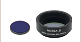
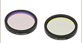
NE20B-B
(Ø25 mm)
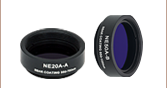
NE550B-B
(Ø1/2")
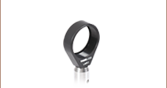
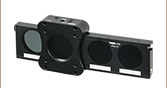
Application Idea
NE505B-B Mounted in LMR05


Please Wait
| Table 1.2 Neutral Density Filter Selection Guide | |
|---|---|
| Absorptive | |
| Uncoated (400 - 650 nm) |
Mounted |
| Unmounted | |
| Uncoated (1000 - 2600 nm) |
Mounted |
| Unmounted | |
| AR Coated (350 - 700 nm) |
Mounted |
| Unmounted | |
| AR Coated (650 - 1050 nm) |
Mounted |
| Unmounted | |
| AR Coated (1050 - 1700 nm) |
Mounted |
| Unmounted | |
| Variable | |
| Reflective | |
| UV Fused Silica (200 - 1200 nm) |
Mounted |
| Unmounted | |
| N-BK7 (350 - 1100 nm) |
Mounted |
| Unmounted | |
| ZnSe (2 - 16 µm) |
Mounted |
| Unmounted | |
| Wedged UVFS (200 - 1200 nm) | |
| Wedged N-BK7 (350 - 1100 nm) | |
| Wedged ZnSe (2 - 16 µm) | |
| Variable | |
| Neutral Density Filter Kits | |

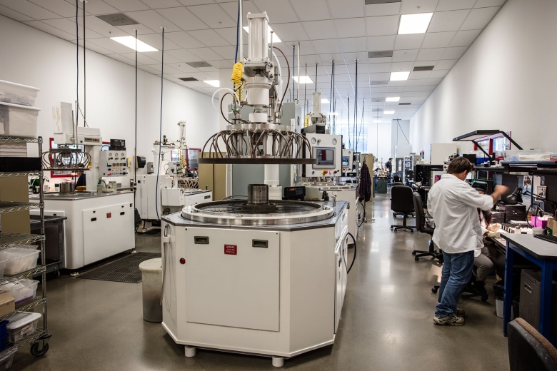
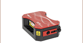
Click to Enlarge
Figure 1.1 One of Our Grinding Machines That is Used to Manufacture ND Filters
Features
- Attenuate Light in the Near IR (650 - 1050 nm AR Coating)
- Optical Densities at 633 nm Prior to Coating: 0.1 to 6.0
- Unmounted Ø1/2" and Ø25 mm Versions
- AR Coated to Reduce Back Reflections in an Optical System
- Ideal for Low-Power Applications (<1 Watt)
Thorlabs is pleased to offer its most popular unmounted absorptive neutral density filters with a broadband antireflection coating for the 650 - 1050 nm range deposited on both surfaces. These filters are also available in mounted versions or with a broadband AR coating for the 350 - 700 nm range. Please see Table 1.2 for more information.
The high-performance, multilayer broadband B coating deposited on each filter is designed to minimize surface reflections within the 650 - 1050 nm range, thereby reducing the amount of stray light present. These coatings provide an average reflectance that is less than 0.5% per surface over the specified wavelength range when light is normally incident on the filter surface. Typical transmission data is available by clicking on the blue info icons (![]() ) in Tables G1.1 through G2.2.
) in Tables G1.1 through G2.2.
Unlike metallic neutral density filters, each absorptive ND filter is fabricated from one member of a family of Schott glasses (see the Specs tab for more information). Each Schott glass has a spectrally flat absorption coefficient. By varying the type of glass used and the thickness of that glass, we are able to produce our entire line of absorptive ND filters from just four types of Schott glass. See Tables G1.1 through G2.2 for detailed information about the average transmission obtained with each of our AR-coated absorptive neutral density filters.
Optical Density and Transmission
Optical density (OD) indicates the attenuation factor provided by an optical filter, i.e. how much it reduces the optical power of an incident beam. OD is related to the transmission, T, by the equation
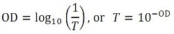
where T is a value between 0 and 1. Choosing an ND filter with a higher optical density will translate to lower transmission and greater absorption of the incident light. For higher transmission and less absorption, a lower optical density would be appropriate. As an example, if a filter with an OD of 2 results in a transmission value of 0.01, this means the filter attenuates the beam to 1% of the incident power. Please note that the transmission data for our neutral density filters is provided in percent (%).
Please note that these products are not designed for use as laser safety equipment. For lab safety, Thorlabs offers an extensive line of safety and blackout products, including beam blocks, that significantly reduce exposure to stray light.
Click to Enlarge
Figure 1.3 Transmission and Optical Density of -B Coated ND Filters with ODs from 0.1 to 1.5. The values in the legend are the typical optical densities at 633 nm for each optic prior to coating. The blue shaded region indicates the wavelength range for which the AR coating performance is specified.
Click to Enlarge
Figure 1.4 Transmission and Optical Density of -B Coated ND Filters with ODs from 2.0 to 6.0. The values in the legend are the typical optical densities at 633 nm for each optic prior to coating. The blue shaded region indicates the wavelength range for which the AR coating performance is specified.
| Optical Density (OD)a |
OD Tolerancea |
Substrate | Substrate Thicknessb |
Ø1/2" Item # |
Ø25 mm Item # |
|---|---|---|---|---|---|
| 0.1 | ±0.01 | NG11 | 0.6 mm | NE501B-B | NE01B-B |
| 0.2 | ±0.01 | NG11 | 1.4 mm | NE502B-B | NE02B-B |
| 0.3 | ±0.015 | NG11 | 2.3 mm | NE503B-B | NE03B-B |
| 0.4 | ±0.02 | NG4 | 0.7 mm | NE504B-B | NE04B-B |
| 0.5 | ±0.025 | NG4 | 0.9 mm | NE505B-B | NE05B-B |
| 0.6 | ±0.03 | NG4 | 1.1 mm | NE506B-B | NE06B-B |
| 0.7 | ±0.04 | NG4 | 1.3 mm | NE507B-B | NE07B-B |
| 0.8 | ±0.05 | NG4 | 1.5 mm | NE508B-B | NE08B-B |
| 0.9 | ±0.05 | NG4 | 1.7 mm | NE509B-B | NE09B-B |
| 1.0 | ±0.05 | NG4 | 1.9 mm | NE510B-B | NE10B-B |
| 1.3 | ±0.065 | NG4 | 2.5 mm | NE513B-B | NE13B-B |
| 1.5 | ±0.08 | NG4 | 2.9 mm | NE515B-B | NE15B-B |
| 2.0 | ±0.1 | NG9 | 1.4 mm | NE520B-B | NE20B-B |
| 3.0 | ±0.15 | NG9 | 2.1 mm | NE530B-B | NE30B-B |
| 4.0 | ±0.2 | NG9 | 2.8 mm | NE540B-B | NE40B-B |
| 5.0 | ±0.25 | NG9 | 3.6 mm | NE550B-B | NE50B-B |
| 6.0 | ±0.3 | NG1 | 1.5 mm | NE560B-B | NE60B-B |
| General Specifications | ||
|---|---|---|
| Diameter | 12.7 mm | 25.0 mm |
| Diameter Tolerance | +0.00 / -0.25 mm | |
| Clear Aperture | >Ø11.43 mm | >Ø20.0 mm |
| AR Coating Range | 650 - 1050 nm | |
| Reflectance (Average) | <0.5% per Surfacea | |
| Surface Quality | 60-40 Scratch-Dig | |
| Parallelism | <10 arcsec | |
| For OD < 1.3 | ||
| Transmitted Wavefront Error (TWE) | <λ/4 (@ 633 nm) | <λ/4 (@ 633 nm) |
| For OD ≥ 1.3 | ||
| Surface Flatness | <λ/4 (@ 633 nm) | - |
| Transmitted Wavefront Error (TWE) | - | <λ/4 (@ 633 nm) |
Click to Enlarge
Click Here for Raw Data
Figure 2.1 The blue shaded region indicates the 650 - 1050 nm wavelength range over which the AR coating provides <0.5% average reflectance per surface.
| Posted Comments: | |
Francis Guay
(posted 2024-08-21 06:21:45.41) What the uncertainty on OD at 1030nm for this filter.
is it in the range OD1.3 +/- 0.1 cdolbashian
(posted 2024-10-28 11:43:47.0) Thank you for reaching out to us with this inquiry. Although we aim to have such a tolerance, the design of these is ultimately "best effort" across the full AR coating range. You can see the expected performance from the graph on the product page. If you need a specific performance at a specific wavelength (such as 1030nm), we are happy to pre-screen your filters as a service to ensure that they fall within your required tolerances. Guodong Peng
(posted 2023-08-17 09:55:22.78) The anti-reflection ND filters are very useful in machine vision, reducing the amount of stray light and enhancing image quality. But there are too few size options, only providing Ø1/2" and Ø25 mm. In industry applications, the clear aperture of lens are usually 30~40 mm. Is there any possibility that you provide anti-reflection ND filters with a diamter of 33 mm? jpolaris
(posted 2023-08-17 05:43:01.0) Thank you for contacting Thorlabs. Requests for customizations such as larger-diameter versions of our optics can be made by emailing us at techsupport@thorlabs.com. I have reached out to you directly to discuss the feasibility of this request. Shadia Chowdhury
(posted 2023-02-16 10:25:43.867) Dear Sir/Madam,
Is there any polarization-dependent loss of these filters? If yes can you please specify it? Because the purpose I bought these filters is polarization sensitive, that is why I need to know exactly how much the polarization changes during the transmission of the laser beam.
Thanks cdolbashian
(posted 2023-02-17 11:08:00.0) Thank you for reaching out to us with this inquiry. These absorptive filters are made from isotropic NG4 glass. Besides the expected effects derived from the Fresnel equations, you should not expect to see any phase/polarization-related effects. I have reached out to you directly to discuss your concerns and application. Bob Wang
(posted 2022-09-30 08:33:29.56) Following up on the comment about the damage thresholds below, we are planning on using an even higher power laser. The average power can reach 1.5 W and the peak power 180 kW. The pulse width is 100 fs and repetition is 80 MHz. We are planning to use these filters to reduce the power output immediately upon laser output, where the beam diameter is 2 mm. Can this product withstand fluences that high? If not, can you recommend one of your products that can? Thanks! cdolbashian
(posted 2022-10-31 01:08:21.0) Thank you for reaching out to us with this inquiry Bob! Unfortunately though, we have not tested our optics under high speed pulses such as these. At this time, we cannot really say for sure whether or not our filters would be damaged by such a source. Alternatively, perhaps you would consider our wedged beamsplitter, which produces multiple refracted beams of different fractional amounts of the source beam, and is designed for higher-power lasers. (https://www.thorlabs.com/newgrouppage9.cfm?objectgroup_ID=6249) Cristina Amaya
(posted 2022-06-21 16:20:10.673) Dear Thorlabs team,
can you recommend me which lens mount to use to mount the NE20B-B filter (25 mm in diameter)? Can I use for example a 1" mount and retaining rings to fix it?
Best regards, jdelia
(posted 2022-06-22 12:56:52.0) Thank you for contacting Thorlabs. The NE20B-B can be mounted in the LMR1(/M) and held in place using the included SM1RR retaining ring. Giuseppe Napolano
(posted 2022-03-08 09:50:03.3) I noticed that damage thresholds are not available for these ND filters. Are the filters suitable for high frequency lasers, e.g. 50kHz? I was considering a 905nm laser, with 2.5ns pulse length, 28W peak power, 3.5 mW average power, 85umx10um spot. jdelia
(posted 2022-03-09 03:53:43.0) Thank you for contacting Thorlabs. Based on the information you have provided, it should be fine to use your laser with these filters. Jindřich Vondruška
(posted 2021-10-01 03:51:37.59) The RoHS certificate is not available! Pleas repair it. YLohia
(posted 2021-10-11 02:51:04.0) Thank you for contacting Thorlabs. The RoHS certificate has been repaired and reuploaded. Linas Svilainis
(posted 2021-05-28 10:13:14.517) Damage threshold for NE510B-B ...NE530B-B series is not given. Does it means that there is no LIDT for these ND filters? YLohia
(posted 2021-06-09 02:26:59.0) Thank you for contacting Thorlabs. That's correct, we currently do not have LIDT for these filters. While we don't have formal damage thresholds for these, given the low average power, we would expect these filters to be fine for your input specs of 905 nm, 120 W peak, 100 ns, 10 Hz, 220 um x 10 um spot jochen.philippi
(posted 2014-09-24 16:05:02.983) Where can i find the refraction index of NE60B-B near 1000um wavelength ?
Thanks !
Jochen jlow
(posted 2014-09-25 09:09:50.0) Response from Jeremy at Thorlabs: The glass used in the filter is NG1 from Schott. I will contact you directly for this info. |
| Table G1.2 Key Specifications | |||
|---|---|---|---|
| Item # | Transmission Dataa | OD at 633 nmb | Thicknessc |
| NE510B-B | 1.0 ± 0.05 | 1.9 mm | |
| NE513B-B | 1.3 ± 0.065 | 2.5 mm | |
| NE515B-B | 1.5 ± 0.08 | 2.9 mm | |
| NE520B-B | 2.0 ± 0.1 | 1.4 mm | |
| NE530B-B | 3.0 ± 0.15 | 2.1 mm | |
| NE540B-B | 4.0 ± 0.2 | 2.8 mm | |
| NE550B-B | 5.0 ± 0.25 | 3.6 mm | |
| NE560B-B | 6.0 ± 0.3 | 1.5 mm | |
| Table G1.1 Key Specifications | |||
|---|---|---|---|
| Item # | Transmission Dataa | OD at 633 nmb | Thicknessc |
| NE501B-B | 0.1 ± 0.01 | 0.6 mm | |
| NE502B-B | 0.2 ± 0.01 | 1.4 mm | |
| NE503B-B | 0.3 ± 0.015 | 2.3 mm | |
| NE504B-B | 0.4 ± 0.02 | 0.7 mm | |
| NE505B-B | 0.5 ± 0.025 | 0.9 mm | |
| NE506B-B | 0.6 ± 0.03 | 1.1 mm | |
| NE507B-B | 0.7 ± 0.04 | 1.3 mm | |
| NE508B-B | 0.8 ± 0.05 | 1.5 mm | |
| NE509B-B | 0.9 ± 0.05 | 1.7 mm | |
| Table G2.2 Key Specifications | |||
|---|---|---|---|
| Item # | Transmission Dataa | OD at 633 nmb | Thicknessc |
| NE10B-B | 1.0 ± 0.05 | 1.9 mm | |
| NE13B-B | 1.3 ± 0.065 | 2.5 mm | |
| NE15B-B | 1.5 ± 0.08 | 2.9 mm | |
| NE20B-B | 2.0 ± 0.1 | 1.4 mm | |
| NE30B-B | 3.0 ± 0.15 | 2.1 mm | |
| NE40B-B | 4.0 ± 0.2 | 2.8 mm | |
| NE50B-B | 5.0 ± 0.25 | 3.6 mm | |
| NE60B-B | 6.0 ± 0.3 | 1.5 mm | |
| Table G2.1 Key Specifications | |||
|---|---|---|---|
| Item # | Transmission Dataa | OD at 633 nmb | Thicknessc |
| NE01B-B | 0.1 ± 0.01 | 0.6 mm | |
| NE02B-B | 0.2 ± 0.01 | 1.4 mm | |
| NE03B-B | 0.3 ± 0.015 | 2.3 mm | |
| NE04B-B | 0.4 ± 0.02 | 0.7 mm | |
| NE05B-B | 0.5 ± 0.025 | 0.9 mm | |
| NE06B-B | 0.6 ± 0.03 | 1.1 mm | |
| NE07B-B | 0.7 ± 0.04 | 1.3 mm | |
| NE08B-B | 0.8 ± 0.05 | 1.5 mm | |
| NE09B-B | 0.9 ± 0.05 | 1.7 mm | |