 Products Home / Active Optical Devices / Electro-Optic Modulators / Automatic Bias Controllers for Lithium Niobate (LiNbO3) Modulators
Automatic Bias Controllers for Lithium Niobate (LiNbO3) Modulators
- Quadrature, Peak, and Null Automated Modes
- Ditherless and Constant Bias Modes
- Built-In VOA for Power Control
- Three Models for Wavelengths from 770 nm to 1610 nm
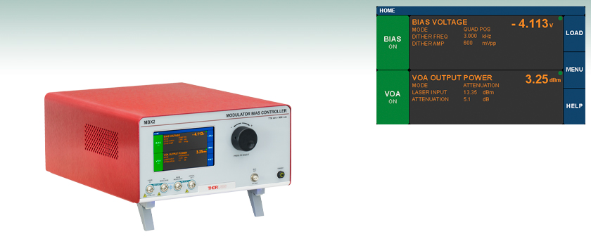
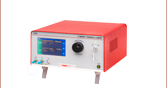
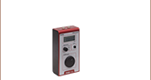
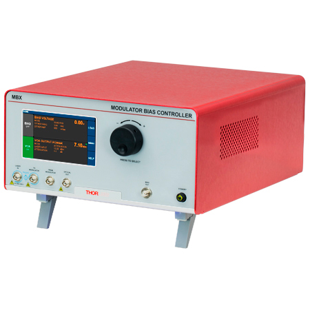
Touchscreen interface shown with external laser source
and fiber-coupled EO modulator connected to the bias controller.
MBX2
Bias and Power Controller for External Modulators,
770 - 980 nm Wavelength Range


Please Wait
Click to Enlarge
Figure 1.1 Block Diagram of the Internal Setup of MBX Series Modulator Bias Controllers
See the Operation tab for details.
Got Questions?
Our engineers and expertise are here for you!

Adam Knapp
Ultrafast Optoelectronics
General Manager
If you are not sure whether our catalog items meet your needs, we invite you to contact us. Or ask about a loan, so you can try them out for yourself, in your own lab. We can also support custom or OEM requirements you may have.
Just press the button, and we'll get back to you within the next business day.

Features
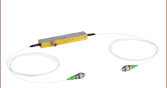
- Designed for Fiber-Coupled LiNbO3 Intensity Modulators
- Three Versions for Different Wavelength Ranges:
- MBX2 Controller: 770 - 980 nm
- MBX3 Controller: 980 - 1310 nm
- MBX Controller: 1250 - 1610 nm
- Fully Automated or Fixed-Voltage Bias Control for Intensity Modulators
- Dithered Operation in Automated Quadrature, Peak, and Null Set Point Modes
- Ditherless Operation in Automated Constant Ratio Mode
- Ditherless Operation in Fixed-Voltage (Constant Bias) Mode
- Built-In Variable Optical Attenuator (VOA) for Automatic or Manual Power Control
- Three Calibration Wavelengths per Controller:
- MBX2 Controller: 785 nm, 852 nm, and 940 nm
- MBX3 Controller: 980 nm, 1064 nm, and 1310 nm
- MBX Controller: 1310 nm, 1550 nm, and 1590 nm
- Control via Intuitive Touchscreen Interface or Remotely using USB or RS-232 Connections
Thorlabs' MBX Series Bias Controllers provide complete and precise control of DC bias and optical output power for fiber-coupled lithium niobate (LiNbO3) electro-optic intensity modulators, regardless of signal speed. Three models are available with three different wavelength ranges spanning 770 nm to 1610 nm. Each model has three selectable power calibration points (See the Features tab or Specs tab for more details). Whether operated in an R&D laboratory or manufacturing environment, these fully-featured modulator bias controllers are ideal for use within a customized setup that uses an external laser, LiNbO3 intensity modulator, signal source, and RF amplifier.
Several operation modes are provided. Automated bias control operation continuously adjusts the DC bias voltage to maintain the correct set point, and there are dithered and ditherless options. When operating in a dithered control mode, an adjustable dither tone with a user-selectable frequency between 1 and 10 kHz is used as a pilot tone. Each automated dithered mode biases the modulator at a different operating point (Peak, Null, or Quadrature); all operating points are referenced to the modulator transmission function described in the Operation tab. If the application requires automated, but ditherless, bias control of the modulator, Constant Ratio mode may be chosen. It is also possible to operate each controller in the fixed-voltage and ditherless Constant Bias mode, in which a user-selected DC bias voltage is applied to the modulator. This mode can be useful for brief measurements, but its inability to track modulator drift renders it impractical for measurements longer than a few minutes.
MBX series controllers can be controlled in two ways. The simplest method is using the intuitive touchscreen interface, which gives the user complete control over all instrument functionality. These instruments can also be operated remotely via the RS-232 or USB ports on the back panel. The Operation tab describes graphical user interface (GUI) and user-customizable features, and we provide a remote control user guide and a remote control software tool (see the Software tab) for download.
Closely Related Items
These controllers are part of a range of fiber-coupled LiNbO3 electro-optic modulator driver and control instruments developed by Thorlabs to meet a variety of application requirements. The key features of each instrument in the range are listed in the Selection Guide tab. Please contact the Ultrafast Optoelectronics Team if your application requires a driver or controller with additional customization. We also offer a full range of LiNbO3 modulators for use with these instruments.
| General System Specificationsa | |||
|---|---|---|---|
| Item # | MBX2 | MBX3 | MBX |
| System | |||
| Optical Input Power (from External Laser) |
20 dBm (Maximum) 22 dBm (Absolute Maximum) |
||
| Wavelength Range | 770 - 980 nm | 980 - 1310 nm | 1250 - 1610 nm |
| Power Calibration Wavelengths |
785 nm, 852 nm, and 940 nm | 980 nm, 1064 nm, and 1310 nm | 1310 nm, 1550 nm, and 1590 nm |
| Bias Voltage Range | ±10 V | ||
| Bias Modes | Quadrature (Positive and Negative Slope) Peak Null Manual (Constant Ratio and Constant Bias) |
||
| Dither Frequency Rangeb | 1 to 10 kHz | ||
| Dither Amplitude Rangeb | 20 mV to 2 V | ||
| Internal Optical Fiber | PM780-HP | PM980-XP | PM Ports: PM1300-XP SM Ports: SMF-28c |
| Internal Controld | |||
| Power Monitor Accuracye | ±0.5 dBm | ||
| Power Monitor Resolutione | 0.01 dBm | ||
| Power Monitor Insertion Lossf | 0.15 dB | 0.1 dB | |
| VOA Insertion Loss | 0.75 dB | 0.4 dB | |
| VOA Response Time | 1 s | ||
| Connectors | |||
| Fiber Connectors | FC/APC, 2.0 mm Narrow Key | FC/APC, 2.0 mm Narrow Key | FC/PC, 2.0 mm Narrow Key |
| Bias Out | SMA Female | ||
| I/O | HD-DB15 | ||
| RS-232 | DB9 | ||
| Mechanical | |||
| Dimensions | 322.3 mm x 250.0 mm x 134.8 mm (12.69" x 9.84" x 5.31") |
||
| Weight | 3.8 kg (8.4 lbs) | ||
| Power and Environmental Specifications | ||
|---|---|---|
| Parameter | Min | Max |
| Main AC Voltage | 100 VAC | 250 VAC |
| Power Consumption | - | 60 VA |
| Line Frequency | 50 Hz | 60 Hz |
| Operating Temperature | 10 °C | 40 °C |
| Storage Temperature | 0 °C | 50 °C |
| Humiditya | 5% Relative Humidity | 85% Relative Humidity |
Click to Enlarge
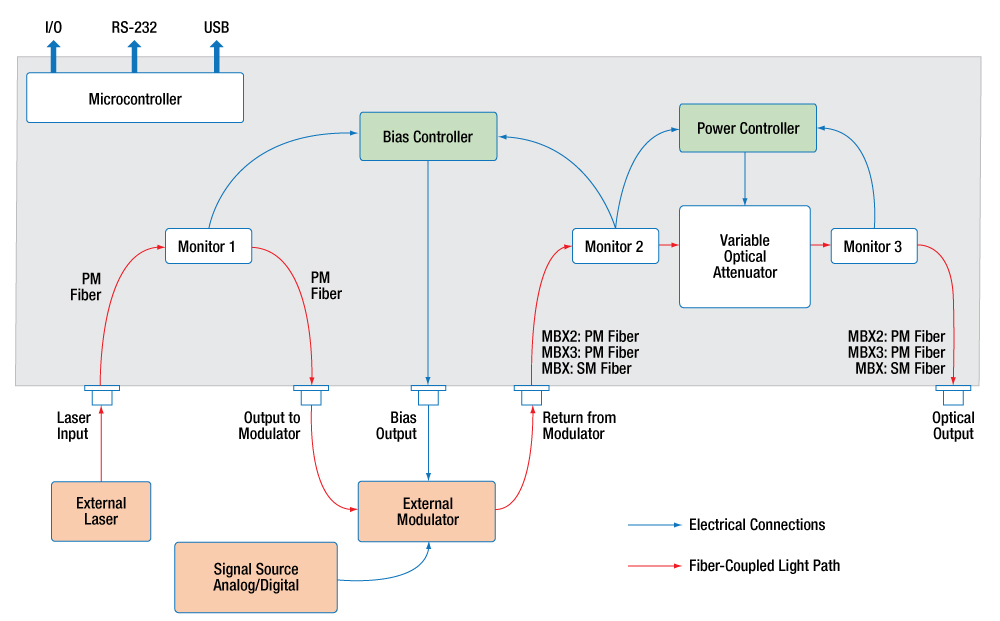
Figure 3.1 Block Diagram of the Internal Setup of MBX Series Modulator Bias Controllers
See the Operation tab for details.
System Overview
Figure 3.1 illustrates the internal setup of MBX series modulator bias controllers. The fiber-coupled light path is traced by the red arrows, and the blue arrows show the electrical connections. The optical laser power is coupled to the Laser Input port and read by Monitor 1 before exiting to the external modulator. The optical output of the modulator is coupled to the Return from Modulator port and routed through the variable optical attenuator (VOA)-based power control system before exiting as the Final Optical Output. Automatic and Manual bias control is performed by referencing intensity readings from Monitor 1 and Monitor 2, and the power controller uses intensity readings from Monitor 2 and Monitor 3 to control and stabilize the output optical power. The rear panel features output ports for several additional monitor and control functions.
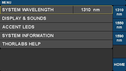
Click to Enlarge
Figure 3.3 System Wavelength Selection Screen
Click to Enlarge
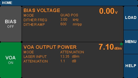
Figure 3.2 Home Screen
Click to Enlarge
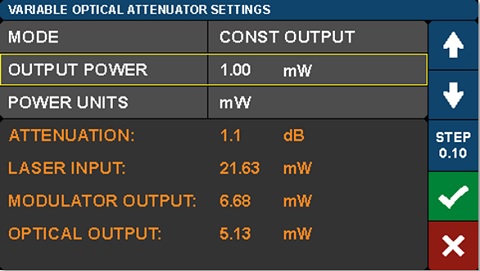
Figure 3.7 VOA Settings Screen to Adjust Output Power
Instrument Control
The graphical user interface (GUI) gives the user complete control over all instrument functionality. Each modulator controller uses a resistive touchscreen display sensitive to both finger pressure and taps from a plastic stylus. The knob on the front panel of the housing can be used in place of the on-screen arrow buttons to quickly change setpoint values. Pressing (clicking) the knob will confirm a new setpoint value. Additionally, the instruments can be driven using serial commands delivered via connectors on the rear panel. This is described in the remote control user guide, and a Windows program that demonstrates remote control of the converter is available in the Software tab.
The home screen of the controller, shown in Figure 3.2, is organized into three main sections. The green dot that appears in the upper-right of the center column panels indicates that those functions are stable. The dot will blink if that function is still stabilizing.
- Left Column:
- Buttons show the on/off status of the different instrument functions.
- Tap a button to toggle the function on/off.
- Middle Column:
- Current operating parameters of each control function are shown.
- Tap in this column to access the Settings page for each function.
- Right Column:
- Buttons provide access to various utility and help functions.
- Tap to review and customize system settings.
Functions and controls enabled by the GUI are further discussed in the following sections.
System Wavelength Settings
The system wavelength may be selected on the Menu page, which is shown in Figure 3.3. The choice of system wavelength specifies which calibration settings to apply to the intensity monitors in the controller. Change the power monitor calibration wavelength to the value closest to the wavelength of the laser source being used.
The MBX2 controller can be used at wavelengths anywhere between 780 nm and 980 nm and calibration settings are supplied for 785 nm, 852 nm, and 940 nm. The MBX3 controller can be used at wavelength anywhere between 980 nm and 1310 nm and calibration settings are supplied for 980 nm, 1064 nm, and 1310 nm. The MBX modulator controller can be used at wavelengths anywhere between 1250 nm and 1610 nm and calibration settings are supplied for three wavelengths: 1310 nm, 1550 nm, and 1590 nm. These wavelengths represent the centers of the O-Band, C-Band, and L-Band.
Modulator Bias Controller
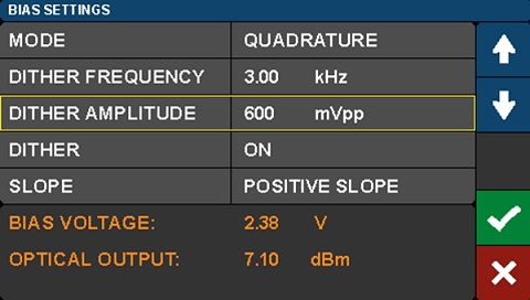
The bias controller and VOA settings can be adjusted using pages accessed by touching the center region of the Home page. A setting screen for the Quadrature mode of the bias controller is shown in Figure 3.4. The parameters written in white font are modified using the function buttons, which are customized for each parameter and stacked in the column to the right of the screen. The parameters in orange font may be monitored here, but not set. Toggle Dither on and off by tapping its value in the center column of the screen. Dither is discussed in more detail in the following section. In this screen shot, Dither Amplitude is selected and its set point value can be adjusted by tapping the arrows on the right of the touchscreen. Tap the check mark to confirm a value, and the X to cancel any changes. Set point values may also be quickly changed by dialing the knob on the front panel of the housing. Pressing (clicking) the knob will confirm a new set point value.
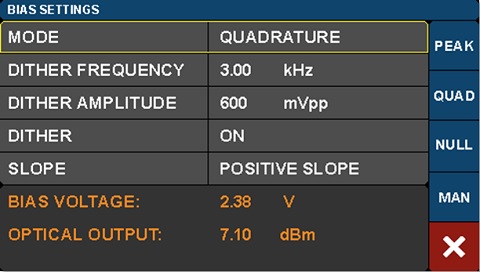
Bias Settings
The Bias Settings screens allow the operator to select among and customize the different operating modes, which are chosen by touching the Mode value and then navigating using the function buttons on the right of the screen. Figure 3.6 shows these function buttons, which are labeled PEAK, QUAD, NULL, and MAN.
Three of the four automated operating modes, Peak, Quadrature, and Null, reference the regions labeled on the modulation transmission function, which is illustrated in Figure 3.5. When one of these modes is selected, a dither tone is used to hold the modulator at the respective bias point. The dither tone is part of a lock-in approach that maintains a stable bias point by compensating for modulator drift, which occurs over time due to the temperature sensitivity of the modulator. The dither tone can be set to a frequency between 1 and 10 kHz, and the amplitude of the tone can also be selected. Quadrature mode gives the option of operating on either the positive or negative slope of the function.
For those applications that require an automated, but ditherless, approach to maintaining a stable bias set point, MBX series controllers include the Constant Ratio mode. It is enabled by tapping the MAN function on the right of the screen shown in Figure 3.6 and configuring the Ratio Set Point and Slope values. This mode adjusts the bias voltage to maintain a chosen ratio between the intensity values reported by Monitor 1 and Monitor 2. The Slope setting allows the user to choose whether increasing voltage on the modulator increases or decreases the optical output power.
It can be useful to operate for brief periods of time at a bias fixed voltage and without a dither tone. The controller allows a fixed bias voltage to be applied in one of two ways. When operating in Quadrature, Peak, or Null modes, tapping the value of Dither will toggle it between on and off states. When dither is toggled off, the value of the fixed bias voltage is held at the most recent automated bias voltage. This enables the user to make quick measurements, without the dither tone present, while the modulator is biased at one of the common modulator transmission function set points. The Constant Bias mode can also be accessed by tapping the Mode value and then the MAN function on the right of the screen. This page allows either the automated Constant Ratio or fixed-voltage Constant Bias modes to be enabled and configured.
Variable Optical Attenuator
The VOA provides the means for adjusting and stabilizing the modulated optical output power. The VOA settings screen, which is shown in Figure 3.7, allows the user to choose between and adjust the parameters of the two operational modes. In Constant Attenuation mode, the attenuation level between the Return from Modulator input port and the Optical Output port is fixed, which allows power fluctuations at the input of the power controller to be transferred to the output. In Constant Output Power Mode, the final optical output power is held constant independent of the input fluctuations. In this mode, the VOA is effectively used as a power stabilizer. Tap the Step function button at the right of the screen to change the step size by which the arrows increment or decrement the set point values.
The VOA settings screen also allows the user to select the units used to report the power readings and parameters on all pages. Use the Power Units field to choose whether power values are reported as mW or dBm.
Rear Panel
The rear panel provides additional utility functions such as the power monitor output, RS-232, and USB ports. Both the USB and RS-232 interfaces can be used for remote control operation of the modulator bias and power controller. The serial commands and control features available are fully described in the remote control user guide. The USB interface is also used for installing firmware upgrades as they become available.

Click to Enlarge
Figure 4.1 MBX Series Modulator Bias Controller Front Panel
Screenshot taken with external laser source and fiber-coupled EO modulator connected.
| Callout | Description | |
|---|---|---|
| 1 | Touchscreen Display and Control | |
| 2 | Value Adjustment Knob | |
| 3 | Laser Input to Bias Controller | |
| MBX2a and MBX3b | Accepts PM Fiber with FC/APC Connector | |
| MBXc | Accepts PM Fiber with FC/PC Connector | |
| 4 | Laser Output to Modulator Input | |
| MBX2a and MBX3b | Accepts PM Fiber with FC/APC Connector | |
| MBXc | Accepts PM Fiber with FC/PC Connector | |
| 5 | Return from Modulator Output to Power Controller | |
| MBX2a and MBX3b | Accepts PM Fiber with FC/APC Connector | |
| MBXd | FC/PC Connector | |
| 6 | Optical Output: Final Optical Output | |
| MBX2a and MBX3b | Accepts PM Fiber with FC/APC Connector | |
| MBXd | FC/PC Connector | |
| 7 | Bias Output to Modulator Input, SMA Female | |
| 8 | On/Standby Button | |
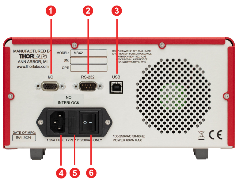
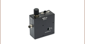
Click to Enlarge
Figure 4.2 MBX Series Modulator Bias Controller Back Panel
| Callout | Description |
|---|---|
| 1a | I/O Control Port, Female HD-DB15 Connector Outputs from Three Integrated Power Monitors |
| 2a | RS-232 Control Port, Male DB9 Connector |
| 3 | USB Port (Type B) |
| 4 | AC Power Cord Connector |
| 5 | Fuse Tray |
| 6 | AC Power Switch |
I/O HD-DB15 Connector
The I/O connector provides analog outputs from the three power monitors.
| Pin | Description | Pin | Description |
|---|---|---|---|
| 1 | Power Monitor 1 | 9 | Analog Ground |
| 2 | Power Monitor 2 | 10 | Analog Ground |
| 3 | Power Monitor 3 | 11 | Reserved for Future Use |
| 4 | Reserved for Future Use | 12 | Reserved for Future Use |
| 5 | Analog Ground | 13 | Power Monitor 1 Gain Indicator |
| 6 | Analog Ground | 14 | Power Monitor 2 Gain Indicator |
| 7 | Analog Ground | 15 | Power Monitor 3 Gain Indicator |
| 8 | Analog Ground | - | - |
RS-232 DB9 Connector
The RS-232 DB9 connector is included to support remote operation.
| Pin | Description |
|---|---|
| 1 | Not Connected |
| 2 | RS232 Input |
| 3 | RS232 Output |
| 4 | Not Connected |
| 5 | Digital Ground |
| 6 | Not Connected |
| 7 | Not Connected |
| 8 | Not Connected |
| 9 | Not Connected |
USB Type B Connector
The USB connector is provided for firmware upgrades and remote operation.
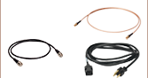
Each Modulator Bias Controller Includes:
- Modulator Bias Controller Main Unit
- Region-Specific Power Cord (Determined by Ordering Location)
- 1.25 A, 250 VAC Fuse
- USB Type A to Type B Cable, 6' Long
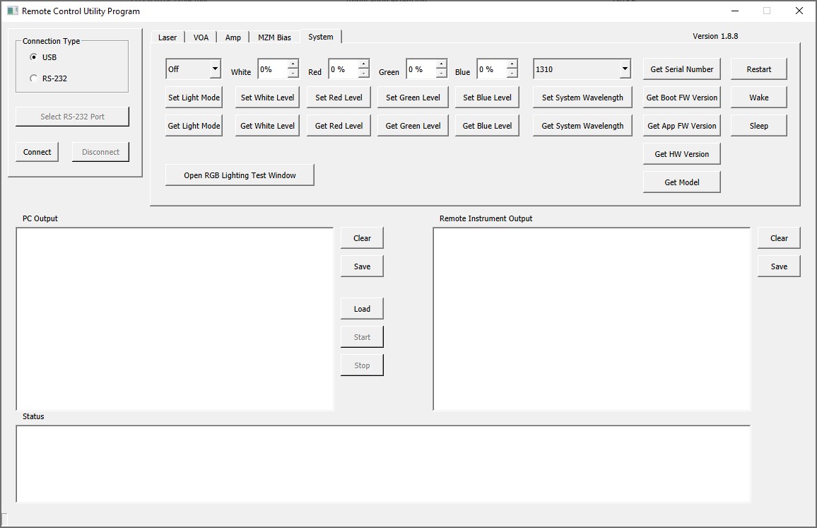
Click to Enlarge
Figure 7.1 The GUI of the Remote Control Software Tool
Software for MBX Series Automated Bias Controllers
Control the Bias Controller Remotely via Serial Commands
Serial commands sent to the bias controller can control the functionality of the internal EO modulator bias controller and variable optical attenuator (VOA), as well as general system parameter settings. The commands can be sent from a computer running any operating system to the RS-232 port on the back panel of the controller. Computers running Windows® 7, or later versions of the operating system, can send serial commands to the USB port on the back panel of the controller. The touchscreen interface remains active while the controller is controlled remotely. Descriptions of how to connect a controlling computer to the controller, the serial command set, and descriptions of each command are included in the Remote Control User Guide.
Application Demonstrating GUI-Based Remote Control of MBX Series Bias Controllers
The Remote Control Software Tool, which is available for download, is an example graphical user interface (GUI) provided for testing, demonstrating, and exploring the use of the different serial commands. This program is not required to operate the controller remotely. It opens a connection to the controller and sends commands in response to buttons clicked by users. Commands sent to the controller, responses from it, and status information messages are logged to the three rectangular fields located beneath the buttons. Please see the Remote Control User Guide for more information. This program can be used as a basis for the development of custom applications. Please
Software
Version 1.8.9 (August 2, 2024)
Click on the Software button to download the Remote Control Software Tool.

Firmware Update
MBX2 - Version 2.1.2 (August 2, 2024)
MBX3 - Version 2.1.2 (August 2, 2024)
MBX - Version 1.8.3 (January 13, 2020)
Click on the Firmware Updates button to download the latest firmware.

Adam Knapp
Ultrafast Optoelectronics
General Manager
Custom and OEM Options
When your application requirements are not met by our range of catalog products or their variety of user-configurable features, please contact me to discuss how we may serve your custom or OEM needs.
Request a Demo Unit
Explore the benefits of using a Thorlabs high-speed instrument in your setup and under your test conditions with a demo unit. Contact me for details.
![]()
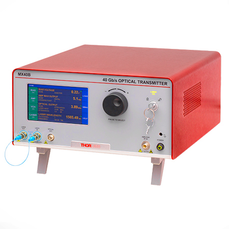
Click to Enlarge
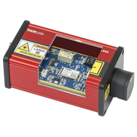
Figure 162A The MX40B Digital Reference Transmitter
Design, Manufacturing, and Testing Capabilities
Thorlabs' Ultrafast Optoelectronics Team designs, develops, and manufactures high-speed components and instrumentation for a variety of photonics applications having frequency responses up to 110 GHz. Our extensive experience in high-speed photonics is supported by core expertise in RF/microwave design, optics, fiber optics, optomechanical design, and mixed-signal electronics. As a division of Thorlabs, a company with deep vertical integration and a portfolio of over 20,000 products, we are able to provide and support a wide selection of equipment and continually expand our offerings.
Our catalog and custom products include a range of integrated fiber-optic transmitters, modulator drivers and controllers, detectors, receivers, pulsed lasers, variable optical attenuators, and a variety of accessories. Beyond these products, we welcome opportunities to design and produce custom and OEM products that fall within our range of capabilities and expertise. Some of our key capabilities are:
- Detector and Receiver Design, to 70 GHz
- Fiber-Optic Transmitter Design, to 110 GHz
- RF & Microwave Design and Simulation
- Design of Fiber-Optic and Photonics Sub-Assemblies
- High-Speed Testing, to 110 GHz
- Micro-Assembly and Wire Bonding
- Hermetic Sealing of Microwave Modules
- Fiber Splicing of Assemblies
- Custom Laser Engraving
- Qualification Testing
Overview of Custom and Catalog Products
Our catalog product line includes a range of integrated fiber-optic transmitters, modulator drivers and controllers, detectors, pulsed lasers, and accessories. In addition to these, we offer related items, such as receivers and customized catalog products. The following sections give an overview of our spectrum of custom and catalog products, from fully integrated instruments to component-level modules.
Fiber-Optic Instruments
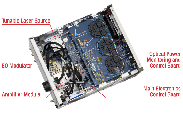
To meet a range of requirements, our fiber-optic instruments span a variety integration levels. Each complete transmitter includes a tunable laser, a modulator with driver amplifier and bias controller, full control of optical output power, and an intuitive touchscreen interface. The tunable lasers, modulator drivers, and modulator bias controllers are also available separately. These instruments have full remote control capability and can be addressed using serial commands sent from a PC.
- Fiber-Optic Transmitters, to 110 GHz
- Linear and Digital Transmitters
- Electrical-to-Optical Converters, to 110 GHz
- Modulator Drivers
- Modulator Bias Controllers
- C- and L-Band Tunable Lasers
Customization options include internal laser sources, operating wavelength ranges, optical fiber types, and amplifier types.
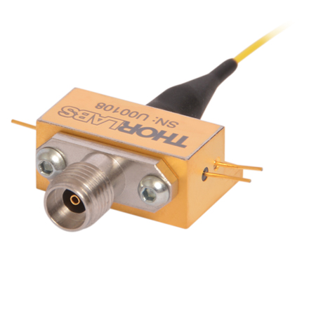
Fiber-Optic Components
Our component-level, custom and catalog fiber-optic products take advantage of our module design and hermetic sealing capability. Products include detectors with frequency responses up to 50 GHz, and we also specialize in developing fiber-optic receivers, operating up to and beyond 40 GHz, for instrumentation markets. Closely related products include our amplifier modules, which we offer upon request, variable optical attenuators, microwave cables, and cable accessories.
- Hermetically-Sealed Detectors, to 50 GHz
- Fiber-Optic Receivers, to 40 GHz
- Amplifier Modules
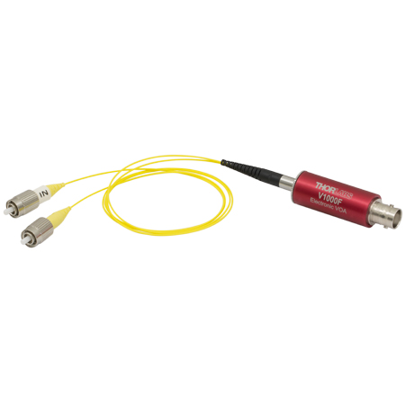
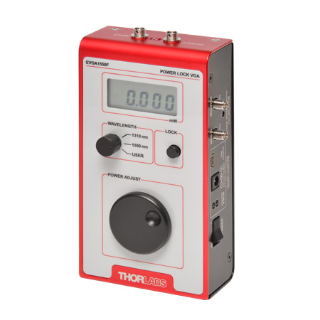
- Electronic Variable Optical Attenuators
- Microwave Cables and Accessories
Customization options include single mode and multimode optical fiber options, where applicable, and detectors optimized for time or frequency domain operation.
Free-Space Instruments
Our free-space instruments include detectors with frequency responses around 1 GHz and pulsed lasers. Our pulsed lasers generate variable-width, nanosecond-duration pulses, and a range of models with different wavelengths and optical output powers are offered. User-adjustable repetition rates and trigger in/out signals provide additional flexibility, and electronic delay-line products enable experimental synchronization of multiple lasers. We can also adapt our pulsed laser catalog offerings to provide gain-switching capability for the generation of pulses in the 100 ps range.
- Pulsed Lasers with Fixed 10 ns Pulse Duration
- Pulsed Lasers with Variable Pulse Width and Repetition Rates
- Electronic Delay Units to Synchronize NPL Series Pulsed Lasers
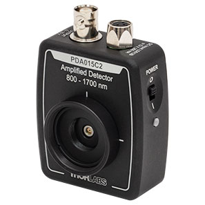
- Amplified Detectors
Customization options for the pulsed lasers include emission wavelength, optical output powers, and sub-nanosecond pulse widths.
| Posted Comments: | |
user
(posted 2021-08-20 17:51:59.73) We are conducting a two-tone IMD test with an EO modulator using the MBX. When increasing the power of the input tones at f1 and f2 monotonically, the power of the output tones go up and down randomly. We believe the MBX is trying to maintain quad bias as the input power is changing. One possible solution we're thinking about is using the MBX to set the DC bias before starting the measurements, then take the MBX offline while conducting the measurements. Should the MBX be able to keep track of the bias changes due to the RF signals? YLohia
(posted 2021-09-01 10:45:56.0) Thank you for contacting Thorlabs. It certainly appears that the MBX is trying to maintain the set point while the input is changing. What's not clear is if the tones are riding on some CW level. The MBX monitors average power, so if the ratio of average power to the tone changes then the final output will be affected by that. We have reached out to you directly to troubleshoot further. |
Choose Optical Transmitter by Application
- Beginning at the left side of Table 136A, choose your desired system characteristics.
- Follow the table to the right and continue to select characteristics from the options within the same row as your previous selection.
- After reaching a Base Item #, choose a laser type. Your system's item # will be your base item # combined with the suffix for your laser type, e.g. MX40B-1310.
| Table 136A Optical Transmitter Selection Guide | ||||||
|---|---|---|---|---|---|---|
| Start Here | Follow the Table to the Right and Choose From These Options | Find Your System Here | ||||
| Modulator Type | Primary Application | Modulation Format | Speed | RF Input | Base Item # | Item # Suffix: Laser Type |
| Amplitude | Time Domain / Eye Diagram | Linear / 4-Level PAM4 | 32 GBaud | Differential | MX35D | No Suffix: C-Band Tunable Laser -LB: L-Band Tunable Laser -1310: 1310 nm Fixed Laser -850: 850 nm Fixed Lasera,b |
| Single Ended | MX35E | |||||
| 56 GBaud | → | MX65E | ||||
| 115 GBaud | → | MX100E | ||||
| Digital / 2-Level NRZ / OOK | 10 Gbps | → | MX10B | |||
| 40 Gbps | → | MX40B | ||||
| 56 Gbps | → | MX50E | ||||
| 56 Gbps | → | MX65E | ||||
| 115 Gbps | → | MX100E | ||||
| Frequency Domain / VNA | → | 40 GHz | → | MX40G | ||
| 70 GHz | → | MX70G | ||||
| 110 GHz | → | MX110G | ||||
| Phase | → | → | 10 Gbps | → | MX10C | |
| 40 Gbps | → | MX40C | ||||
Choose Optical Transmitter Instrument by Features
| Table 136B Transmitter Instruments and Tunable Lasers | |||||||
|---|---|---|---|---|---|---|---|
| Item # | Speed | Internal Laser | Internal Modulator (Type) |
RF Amplifier (Type) |
Bias Controller |
Variable Optical Attenuator (VOA) |
Block Diagram |
| Automatic Bias Controller | |||||||
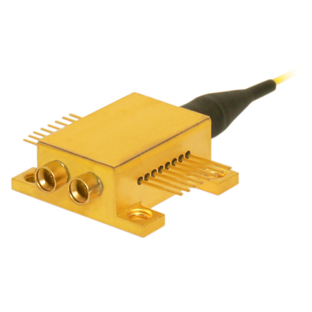
| MBX2 (770 - 980 nm) |
N/A | - | - | - | 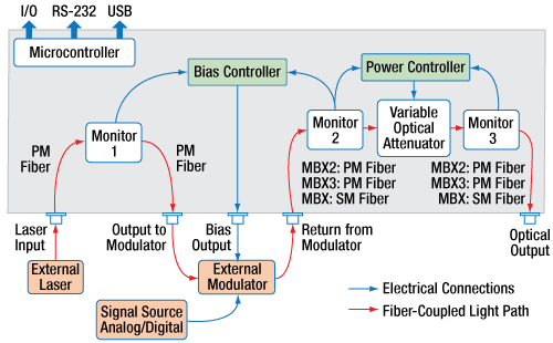 |
||
| MBX3 (980 - 1310 nm) |
N/A | - | - | - | |||
| MBX (1250 - 1610 nm) |
N/A | - | - | - | |||
| Tunable Telecom-Grade Laser Sources | |||||||
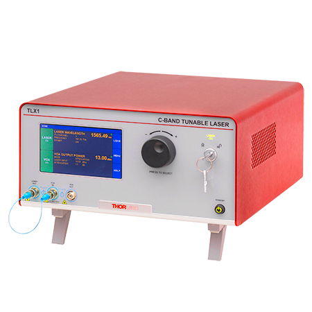
| TLX1 | N/A | C-Band, Tunable | - | - | - |  |
|
| TLX2 | N/A | L-Band, Tunable | |||||
| High-Speed Modulator Drivers | |||||||
| MX10A (1250 - 1610 nm) |
12.5 Gb/sa | - | - | Digital |  |
||
| MX40A (1250 - 1610 nm) |
40 Gb/sa | ||||||
| High-Speed Optical Transmitters | |||||||
| MX10B | 12.5 Gb/sa | C-Band, Tunable | Intensity | Digital | 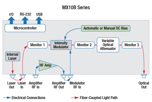 |
||
| MX10B-LB | 12.5 Gb/sa | L-Band, Tunable | |||||
| MX10B-1310 | 12.5 Gb/sa | 1310 nm, Fixed | |||||
| MX10C | 12.5 Gb/sa | C-Band, Tunable | Phase | Digital | - | 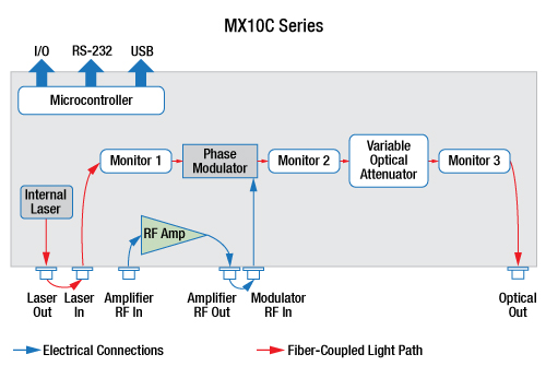 |
|
| MX10C-LB | 12.5 Gb/sa | L-Band, Tunable | |||||
| MX10C-1310 | 12.5 Gb/sa | 1310 nm, Fixed | |||||
| MX35E | 35 GHzb | C-Band, Tunable | Intensity | Linear |  |
||
| MX35E-LB | 35 GHzb | L-Band, Tunable | |||||
| MX35E-1310 | 35 GHzb | 1310 nm, Fixed | |||||
| MX35D | 35 GHzb | C-Band, Tunable | Intensity | Linear with Differential Input |
 |
||
| MX35D-LB | 35 GHzb | L-Band, Tunable | |||||
| MX35D-1310 | 35 GHzb | 1310 nm, Fixed | |||||
| MX40B | 40 Gb/sa | C-Band, Tunable | Intensity | Digital | 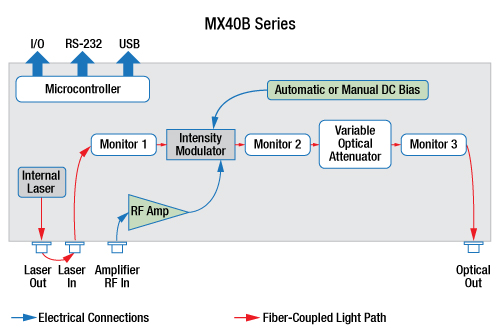 |
||
| MX40B-LB | 40 Gb/sa | L-Band, Tunable | |||||
| MX40B-1310 | 40 Gb/sa | 1310 nm, Fixed | |||||
| MX40C | 40 Gb/sa | C-Band, Tunable | Phase | Digital | - |  |
|
| MX40C-LB | 40 Gb/sa | L-Band, Tunable | |||||
| MX40C-1310 | 40 Gb/sa | 1310 nm, Fixed | |||||
| MX50E-850 | 50 GHzb | 852 nm, Fixed | Intensity | Linear | |||
| MX65E | 65 GHzb | C-Band, Tunable | Intensity | Linear | 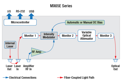 |
||
| MX65E-LB | 65 GHzb | L-Band, Tunable | |||||
| MX65E-1310 | 65 GHzb | 1310 nm, Fixed | |||||
| MX100E | 100 GHzb | C-Band, Tunable | |||||
| MX100E-1310 | 100 GHzb | 1310 nm, Fixed | |||||
| E-O Converters for VNA Applications | |||||||
| MX40G | 40 GHzb | C-Band, Tunable | Intensity | - |  |
||
| MX40G-LB | 40 GHzb | L-Band, Tunable | |||||
| MX40G-850 | 40 GHzb | 850 nm, Fixed | |||||
| MX40G-1310 | 40 GHzb | 1310 nm, Fixed | |||||
| MX70G | 70 GHzb | C-Band, Tunable | Intensity | - | |||
| MX70G-LB | 70 GHzb | L-Band, Tunable | |||||
| MX70G-1310 | 70 GHzb | 1310 nm, Fixed | |||||
| MX70G-DB1 | 70 GHzb | C-Band, Tunable | Intensity | - |  |
||
| 1310 nm, Fixed | |||||||
| MX110G | 110 GHzb | C-Band, Tunable | Intensity | - | 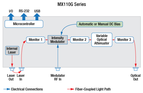 |
||
| MX110G-1310 | 110 GHzb | 1310 nm, Fixed | |||||
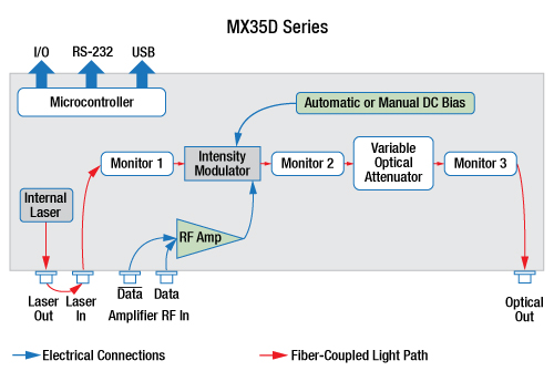
The capabilities of Thorlabs' extensive range of transmitter instruments are summarized in the text and Table 136B. All members of this product series share a similar interface, as well as a common remote control command set.
Automatic Bias Controller
Thorlabs' fully-featured automatic bias controllers provide complete and precise control of DC bias and optical output power for any fiber-coupled LiNbO3 EO intensity modulator, regardless of signal speed. Automatic bias controllers are ideal for use within a customized setup that uses an external laser, intensity modulator, signal source, and RF amplifier. Options are available for wavlengths from 770 nm up to 1610 nm.
Tunable Telecom-Grade Laser Sources
Emitting in the C-band or the L-band, these lasers have narrow typical linewidths of 10 kHz. A frequency dither option aids in stabilizing the laser wavelength, and the integrated variable optical attenuator (VOA) provides optical output power control. These lasers are tunable in 50 GHz steps across the ITU frequency grid, and feature a 1 MHz step size fine-tune capability, as well.
High-Speed Modulator Drivers
With an operational wavelength range of 1250 nm to 1610 nm, each modulator driver provides control for an external fiber-coupled LiNbO3 EO modulator. Each modulator driver includes an RF amplifier with amplitude and eye-crossing controls and accepts an external drive signal source. Models with integrated automatic bias controllers are offered for use with intensity EO modulators.
High-Speed Optical Transmitters
Designed to provide fully-integrated solutions for high-speed light modulation, these systems are built around a LiNbO3 intensity or phase modulator. The MX10B, MX40B, MX10C, and MX40C series of systems include a digital (limiting) RF amplifier, which offers fixed gain and an adjustable output voltage swing. The MX35E, MX50E, MX65E, and MX100E series include a high-bandwidth linear (analog) RF amplifier, making it well suited for pulse amplitude modulation and related applications.
E-O Converters for VNA Applications
With our MX40G, MX70G, and MX110G series of E-O converters, any E-E vector network analyzer can be used to perform optical testing up to 40 GHz, 70 GHz, and 110 GHz respectively. The E-O converter is a fully-integrated solution that includes a laser, a modulator, and bias control.