 Products Home
Telesto® Series PS-OCT Systems

Please Wait
OCT Family Updates
We recently improved the OCT Base Units, and the new additions include:
- Fully Configurable Trigger for Integration into Larger Experiments
- Analog Input for Combining Other Data Sources with the OCT Signal
- Internal Hardware Diagnostics for Improved Troubleshooting
The SD-OCT standard scanners have also been redesigned with a new micrometer screw for more precise reference arm positioning.
New features added to ThorImage®OCT include a despeckle filter, 3D speckle variance mode, and automatic peak detection.
Exploring the Options?

We can provide tailored recommendations and partner with you to obtain images of your samples, demonstrating the impact of the OCT base unit and probe optics on image quality. Demos of our OCT systems can be arranged at our Sterling, VA (USA); Shanghai, China; Tokyo, Japan; and Lübeck, Germany facilities. See the OCT Demo Rooms tab.
In the Budgetary Phase?
System prices vary based on the exact components. Through our conversations, we can ensure your system quote is tailored to your requirements.
OEM or Custom Projects?
Click here to learn about our OEM capabilities.

OCT Applications Team Based in Lübeck, Germany
We're Happy to Assist!

Features
- Single-Input Polarization-Sensitive OCT System with Unique Detector Unit for Simultaneous Acquisition of Both Orthogonal Polarizations at Full Imaging Speed
- Robust Setup for Highly Reproducible Measurements
- Configurable Systems Optimized for High-Resolution, High-Depth Imaging
- 3.5 mm Imaging Depth with 5.5 µm Axial Resolution in Air
(1300 nm Center Wavelength) - 7.0 mm Imaging Depth with 11 µm Axial Resolution in Air
(1325 nm Center Wavelength)
- 3.5 mm Imaging Depth with 5.5 µm Axial Resolution in Air
- Base Units with A-Scan Rates up to 76 kHz or up to 109 dB Sensitivity Available
- Includes Computer and ThorImage®OCT Software Package
(See the Software Tab) - Build-Your-Own and Preconfigured Systems Available
Choose Components to Build or Customize Your OCT System
- Choose from High-Resolution (1300 nm) or Long-Range (1325 nm) Base Units
- Standard and User-Customizable Scanner Available
- Scan Lens Kits to Optimize Lateral Resolution and Focal Length for Your Application
- Ring- and Immersion-Style Sample Z-Spacers for Air or Liquid Imaging Applications
- Scanner Stand and Translation Stage Accessories
- Contact Our OCT Team to Request a Quote and Discuss Building a System
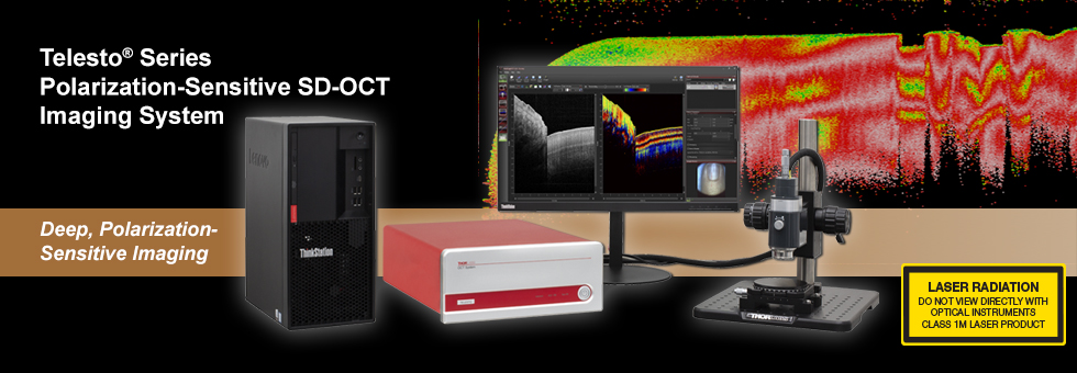
Telesto® Series Polarization-Sensitive OCT (PS-OCT) Systems preserve, detect, and process polarization information of samples through noninvasive, subsurface optical imaging. This technology can uncover normally unobserved features of birefringent samples (e.g. tissue, plastic, or crystals) that stem from the internal microstructure. For example, scar tissue will interact differently with polarized light than regular skin tissue, so the polarization information can be used to add an additional layer of contrast to a standard optical coherence tomography (OCT) image. This additional layer can be characterized as the cumulative retardation, optic axis, or degree of polarization uniformity (DOPU).
OCT is an optical imaging technique that produces real-time, 2D cross-sectional and 3D volumetric images of a sample. This technique provides structural information about the sample based on light backscattered from different layers of material within that sample, producing images with micron-level resolution and millimeters of imaging depth. In addition to high resolution, the non-contact, noninvasive nature of OCT makes it well suited for imaging samples such as biological tissue, small animals, and industrial materials.
The Telesto PS-OCT systems use an incident beam of known polarization and a dual-detector design to incorporate polarization information in 2D cross-sectional and 3D volumetric images of a sample. OCT is typically performed with an incident beam of unknown polarization and a single detector unit. The Telesto PS-OCT systems control the polarization incident on the sample and reflected in the reference arm of the interferometer by using two carefully aligned wave plates. The preserved polarization information is then measured using two detectors (see the PS-OCT Tutorial tab).
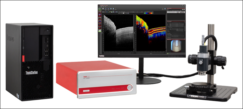
These OCT systems provide the flexibility required for long-range and high-resolution imaging applications. The detector unit is housed in the same box as the standard Telesto systems and features the same robustness as all Thorlabs OCT systems. No calibration or adjustment is needed after shipping or during use. The compact design of the system allows for easy and mobile operation. The 64-bit software pre-installed on the included computer displays and processes 2D and 3D OCT data in real time. Optional accessories are available below to customize your OCT system to meet the requirements of your application. Additionally, Thorlabs offers two complete, preconfigured OCT systems for 1300 or 1325 nm based on the components sold on this page.
The components below can also be used to upgrade your existing Thorlabs OCT system with additional features and are compatible out of the box with the Thorlabs' OCT systems and accessories sold below. While most systems are upgradable, we recommend contacting the OCT Team to determine the optimal solution for your system and intended application.
Click on the Image or in Table 1.2 for Details on Customization Options
| Table 1.2 Telesto Customization Options |
|---|
| OCT Base Unit (Computer Included) |
| Scanning System |
| Scan Lens Kit |
| Reference Length Adapter (For Standard Scanners Only) |
| Adjustable Scanner Stand |
| Translation Stage |
| Preconfigured Systems |
Polarization-Sensitive OCT
With Thorlabs' Telesto® Series Polarization-Sensitive OCT (PS-OCT) Imaging Systems, it is possible to obtain additional information carried by the polarization state of light that has interacted with a sample. When incident light with a defined polarization state is used, changes in the polarization state resulting from the sample can be interpreted. Birefringent material causes a relative delay between two orthogonal polarization states known as phase retardation. This relative delay has an orientation, called the optic axis, which can be visualized with polarization-sensitive OCT. Additionally, the sample can have properties which depolarize the incident polarized light, resulting in an arbitrary polarization state of the light that can be characterized by the degree of polarization uniformity (DOPU). Both these behaviors can be detected with the Telesto PS-OCT systems.
Click for Details
Figure 2.1 PS-OCT System Schematic
System Design
A Telesto PS-OCT system is a phase-stable spectral domain OCT system. It is a single-input device with a unique polarization-sensitive detector unit for simultaneous acquisition of two orthogonal polarization states at full imaging speed. The Telesto PS-OCT system is designed to define the polarization state of light incident on the sample and preserve polarization throughout the system, as shown in Figure 2.1. Starting with linearly polarized light from the superluminescent diode light source, two quarter-wave plates, one in the reference arm and one in the sample arm, are used to alter the polarization state of the light. In the reference arm, the quarter-wave plate has a 22.5° orientation relative to the linearly polarized input; the beam passes through the wave plate twice, so light exits the reference arm with a 45° linear polarization relative to the input light. In the sample arm, the quarter-wave plate is oriented at 45° relative to linearly polarized input light, converting it into circularly polarized light that is incident on the sample. The orientation of these two wave plates enables the system to be as polarization sensitive as possible. In addition to the wave plates, specially designed optical components maintain polarization throughout the whole system.
The detection of two polarization states does not slow down the acquisition rate when compared to the standard TEL211 and TEL221 systems, allowing the same imaging speeds to be achieved. The system was designed with robustness and easy handling in mind. No calibration of the polarization-sensitive detector unit is necessary at any time, as expected from a true turnkey OCT system. The result is a polarization-sensitive OCT system that yields highly reproducible measurements.
Signal Processing
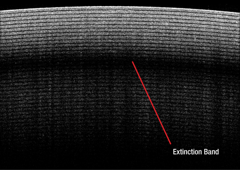
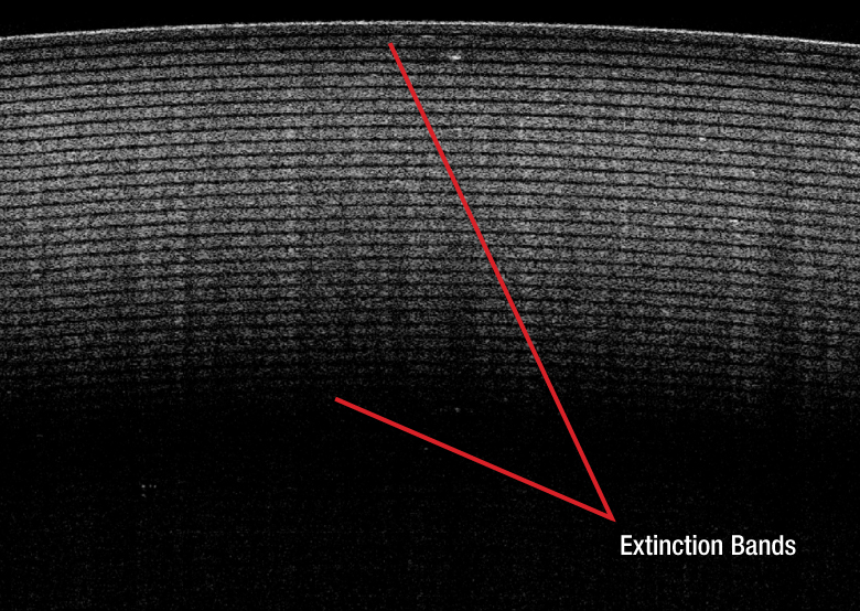
The two individual OCT images from the unique polarization-sensitive detector unit can be shown separately or combined in a total intensity image. Some samples, e.g. scotch tape, may produce changes in polarization state that cause extinction banding. Since the two sensors receive light with orthogonal linear polarizations, the extinction bands will appear in different locations in each image. The total intensity image provides the advantage of eliminating this banding, leading to a better OCT image compared to standard OCT systems.
Click to Enlarge
Figure 2.2 Sensor 1 OCT Image: The polarization mismatch of the light from the sample and reference arm produces extinction bands.
Click to Enlarge
Figure 2.3 Sensor 2 OCT Image: The polarization mismatch occurs at different depths of the sample compared to sensor 1, due to receiving light with the orthogonal linear polarization state.

Click to Enlarge
Figure 2.4 Total Intensity Image: The information of both sensors is combined, producing an optimized OCT image without the banding.
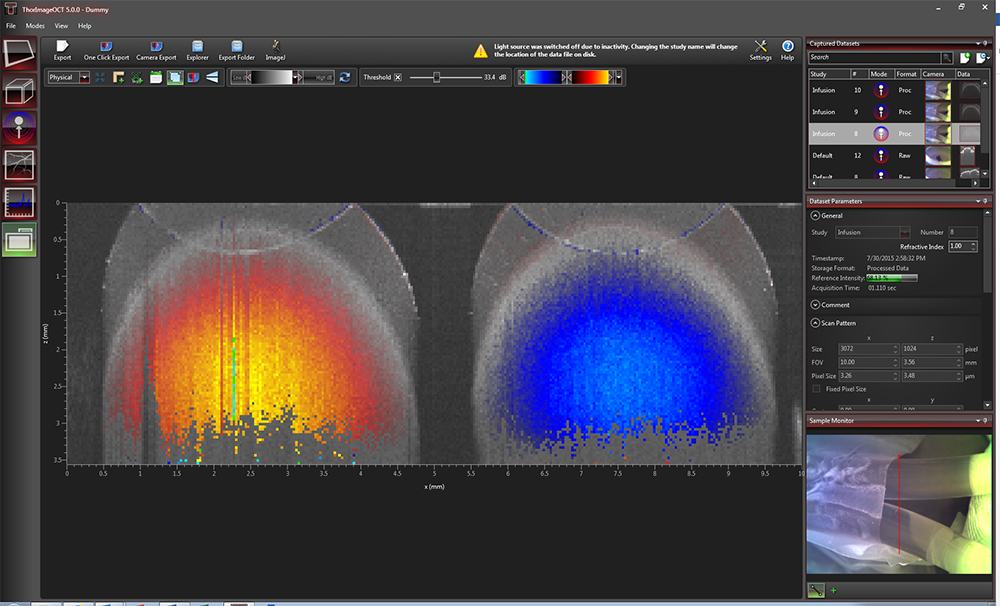
To obtain polarization images, the combination of the information from both sensors (red box in Figure 2.5) is necessary. The information provided by two orthogonal polarization states of interfered light enables the calculation of the Stokes vectors (I, Q, U, V) for each image point. Each one of these values (I = Total Intensity) may be imaged individually, as shown in the purple box in Figure 2.5. In addition, the Stokes vectors describing the polarization state of light can be used to determine several more advanced polarization measurements. As shown in the blue box in Figure 2.5, cumulative retardation, optic axis, or degree of polarization uniformity (DOPU) may be calculated. Example images of tape are shown in Figure 2.5 (click each box to enlarge).
Figure 2.5 A roll of tape is imaged with Thorlabs’ PS-OCT system using orthogonal polarization information from two sensors to calculate Stokes vectors, which are then used to calculate cumulative retardation, optic axis, or DOPU. With our software, it is possible to see all the images shown in the figure separately. For detailed information, please see the Software tab.
ThorImage®OCT Software
Software features:
- Live Acquisition and Simultaneous Display in 1D, 2D, and 3D
- Live Sample Monitor for Easy Sample Positioning and Adjustment of Scan Pattern
- Advanced Dataset Handling
- User Access from Calibration and Raw Data Through to Processed Data
- Various Data Export Options
- Time-Series Measurements
- Doppler, Speckle Variance, and Polarization-Sensitive (PS)a Acquisition Modes
- Lightweight API ThorImageAutomation (C, C#, LabVIEW and Python)
- Low-Level SDK APIs Available In C, LabVIEW, and Python
- Seamless Integration of User-implemented Python Processing in ThorImageOCT Environment
ThorImage®OCT is a high-performance data acquisition software that is included with all Thorlabs OCT systems. This 64-bit Windows-based software acquires and displays OCT data and includes scan control and processing options. Additionally, Python, NI LabVIEW®, and C-based Software Development Kits (SDKs) are available, which contain a complete set of libraries for measurement control, data acquisition, and processing, as well as for storage and display of OCT images. The SDKs provide the means for developing highly specialized OCT imaging software for any individual application. The Python user interface enables user-developed processing routines within the ThorImageOCT live view.
| Table 116B ThorImageOCT Documentation | |
|---|---|
| ThorImageOCT Software Manual | |
| Third-Party Software License Agreements | |
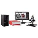
Video 116A shows OCT images of a finger being acquired and manipulated in ThorImageOCT. This is done using the 3D volume and cross section modes. The software manual and third-party license agreements are included in Table 116B.
Explore the functionality of the ThorImageOCT software by clicking the expandable Workspace, Capabilities, Feature Plugins, Integration, and Specifications bars below. See the Specifications bar for a complete list of features and compatibility.
- Specific PS system required.
Workspace
ThorImageOCT streamlines the image acquisition and analysis process with a user-intuitive, feature-rich workflow. Control panels are designed so that the most important features are readily available and users can quickly set up their experiment. Panel layouts are completely customizable for different use cases or imaging modalities. All software features are easily accessible from the main workspace window, providing a complete, self-contained software package.
Click the Highlighted Regions in Figure 116C to Explore the Workspace

Figure 116C ThorImageOCT Workspace Window
Capabilities
| Quick Links |
|---|
| Acquisition |
| Imaging Modes: 1D, 2D, and 3D Scan Control with Sample Monitor Probe Calibration Image Quality and Speed |
| Processing |
| Image Field Correction |
| Image Viewing |
| Viewing Options Dataset Management |
| Analysis |
| Despeckle Filter Marker Tool Surface Detection |
Acquisition
Imaging Modes
Different OCT imaging modes can be selected using the mode selector. If the ThorImageOCT software finds a compatible system connected and switched on, all operational modes will be selectable. If no OCT device is present, only the data viewing mode for viewing and OCT data export will be available.
Click to Enlarge
Figure 116E Several A-Scans at a Single Point Over Time (M-Scan)
Click to Enlarge
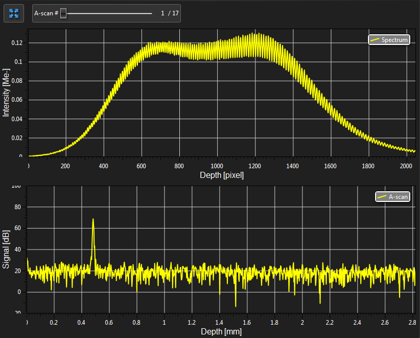
Figure 116D Spectral and Depth Information for a Single Point (A-Scan)
1D Mode
In this mode, single-point measurements can be made that provide spectral and depth information, as well as the ability to observe time-related sample behavior with an M-scan.
Click to Enlarge
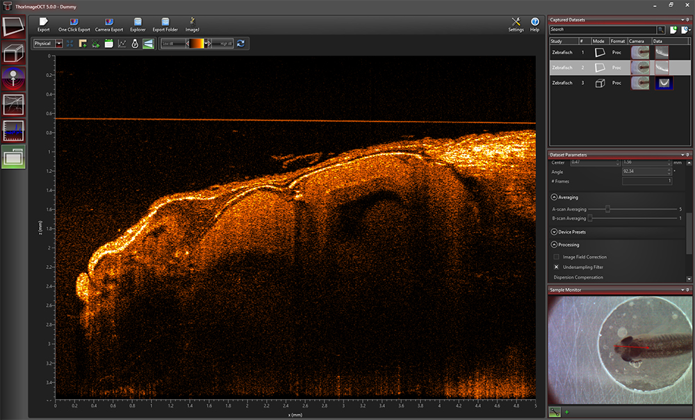
Figure 116F ThorImageOCT Window in the 2D Mode
2D Mode
In the 2D imaging mode, the probe beam scans in one direction, acquiring cross-sectional OCT images that are then displayed in real time. Acquisitions can be stored with Snapshot and Advanced Snapshot. Advanced Snapshot provides optimized averaging options for higher image quality. For long term measurements, a time series function with an adjustable time interval between two acquisitions is included. Image display parameters, such as color mapping, can be controlled in this mode. We have also implemented an option for automatic calculation of the optimum contrast and brightness of the displayed OCT images.
Click to Enlarge
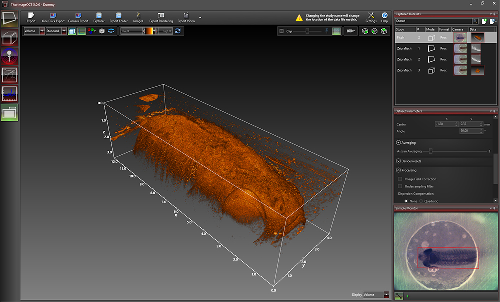
Figure 116G Rendering View in ThorImageOCT
3D Mode
In the 3D imaging mode, the OCT probe beam scans sequentially across the sample to collect a series of 2D cross-sectional images that are then processed to build a 3D image.
Utilizing the full potential of our high-performance software in combination with our high-speed OCT systems, we have included a Fast Volume Rendering Mode in the ThorImageOCT software, which serves as a preview for high-resolution 3D acquisitions. In this mode, high-speed volume renderings can be displayed in real-time, providing rapid visualization of samples in three dimensions.
To accommodate long term measurements, a time series function that takes a series of 3D measurements is available. The number of volumes to be acquired and the time interval between scans are adjustable.
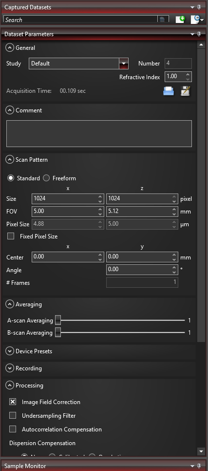
Click to Enlarge
Figure 116H Various acquisition parameters can be adjusted in ThorImageOCT.
Scan Control with Sample Monitor
ThorImageOCT provides numerous scan and acquisition controls. The camera integrated in the scanner of our OCT systems provides live video images in the application software. Defining the scan line for 2D imaging or the scan area for 3D imaging is accomplished through the easy-to-use "Draw and Scan" feature by clicking on the video image.
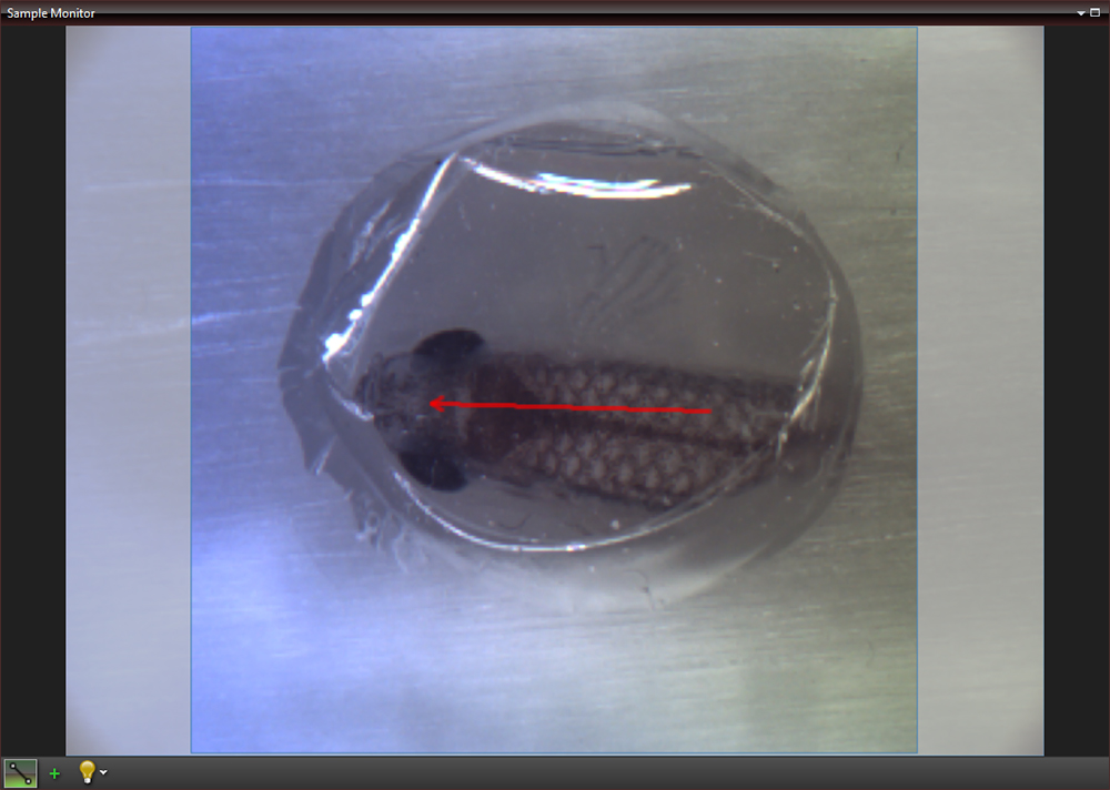
Click to Enlarge
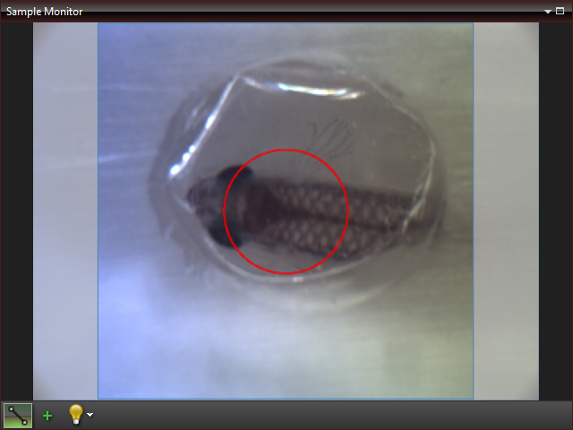
Figure 116J The Sample Monitor can be used to define the scan pattern using the "Draw and Scan" feature.
Arbitrary forms defined by the Draw & Scan feature or loaded .txt files can be scanned. The scan pattern can also be adjusted by specifying suitable parameters in the controls of the software, as shown in Figure 116H.
Click to Enlarge
Figure 116K A predefined circle scan pattern can be loaded and scanned in the software. The size can be changed with the Zoom feature.
Click to Enlarge
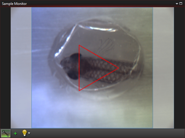
Figure 116L A predefined triangle scan pattern can be loaded and scanned in the software. The size can be changed with the Zoom feature.
Additionally, one can further set processing parameters, averaging parameters, and the speed and sensitivity of the device using device presets. By using a high-speed preset, video-like frame rates in 2D and fast volume rendering in 3D are possible, whereas high-sensitivity acquisition is enabled by choosing a preset with a lower acquisition speed.
Click to Enlarge
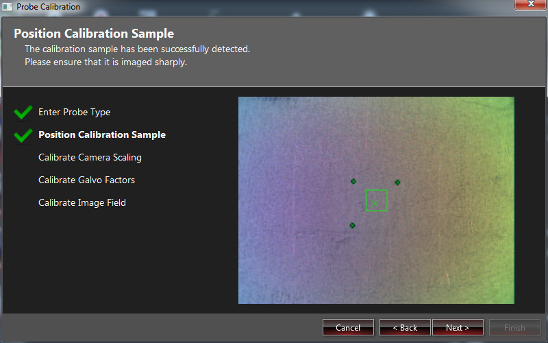
Figure 116M Probe Calibration Window in ThorImageOCT
Probe Calibration
Our camera and scanning system are calibrated to match the real lengths for the scan pattern parameter. Changing to a different scan lens kit will generally require a different probe configuration in order to adapt to changes in the optical parameters of the system. When an additional scan lens is purchased for your Thorlabs OCT scanner system, ThorImageOCT enables you to easily create a fitting configuration for your new scan lens by using the calibration sample shipped with the lens and an intuitive step-by-step calibration process (shown in Figure 116M).
Image Quality and Speed
Depending on the specific application, the balance between image quality and acquisition time may tend more towards one or the other. Several options based on the available hardware are provided to help reach the optimal balance for a given measurement.
Averaging
Averaging the spectra before the Fast Fourier Transform (FFT), or averaging the processed data with A-Scan averaging or B-scan averaging are two options available that can enhance the image quality or the acquisition speed.
Speed and Sensitivity
For camera based systems of the Ganymede and Telesto family, predefined presets of the acquistion speed can be chosen. By using a high-speed preset, video-live frame rates in 2D and fast volume rendering in 3D are possible, whereas high-sensitivity acquistion is enabled by choosing a preset with a lower acquistion speed.
Additional Controls
For the Vega and Atria System families, the Detector Gain is adjustable in ThorImageOCT. Additional controls to match the polarization state of the light from the sample and reference arm as well as a software integrated reference stage to adjust optical length of the reference arm are included.
Processing
ThorImageOCT provides features specifically designed to improve the quality of OCT images. The data can be modified during acquisition using processing parameters, such as image field correction, dispersion correction, and undersampling filters, or afterwards with filters.
Image Field Correction
A calibrated image field correction is included by default with the system. This corrects optical distortions in the axial direction and is demonstrated on scotch tape in Figure 116N and Figure 116P.

Click to Enlarge
Figure 116P Image Field Correction Applied to an OCT Image of Scotch Tape

Click to Enlarge
Figure 116N OCT Image of Scotch Tape
If additional processing functions are desired, ThorImageOCT can also integrate user-defined processing and post-processing algorithms; see the External Programs and User Interface for Python Processing sections in the Integration tab below for more details.
Image Viewing
For all imaging modes, an offline mode is available to view acquired images with ThorImageOCT stored as .oct-files. All legacy .oct-files can be opened with the current version of ThorImageOCT.
Viewing Options
In the ThorImageOCT software, 3D volume datasets can be viewed as orthogonal cross-sectional planes (see Figures 116Q and 116R) and volume renderings. The Sectional View features cross-sectional images in all three orthogonal planes, independent of the orientation in which the data was acquired. The view can be rotated as well as zoomed in and out.
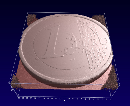
The Rendering View provides a volumetric rendering of the acquired volume dataset. This view enables quick 3D visualization of the sample being imaged. Clip planes of any orientation can be applied. The 3D image can be zoomed in and out as well as rotated. Furthermore, the coloring and dynamic range settings can be adjusted.
Click to Enlarge
Figure 116Q Sectional View in ThorImageOCT
Click to Enlarge
Figure 116R Rendering View in ThorImageOCT
Click to Enlarge
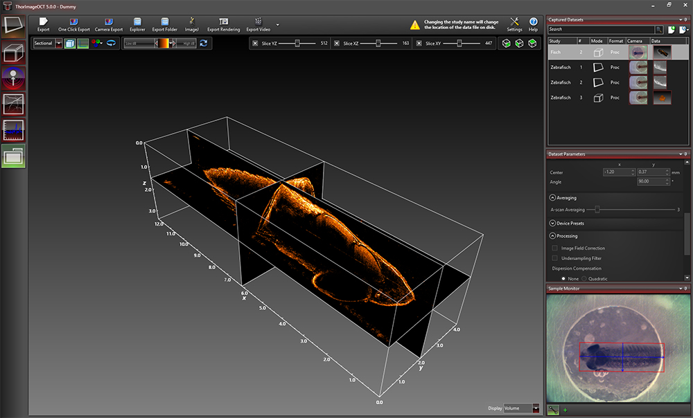
Figure 116T The Dataset Management Window of ThorImageOCT
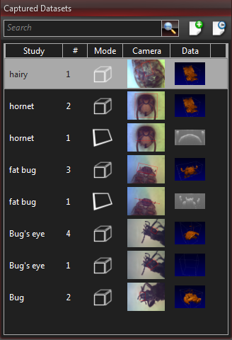
Dataset Management
ThorImageOCT provides advanced dataset management capabilities, which allow several datasets to be opened simultaneously. Datasets are uniquely defined using an identifier consisting of a study (or test series) name and an experiment number. Grouping of datasets can be achieved by using the same study name. The "Captured Datasets" list shows an overview of all open datasets, including the dataset identifier, the acquisition mode, and preview pictures of the still video image and the OCT data.
.oct Files and Export
The OCT file format native to ThorImageOCT allows OCT data, sample monitor data, and all relevant metadata to be stored in a single file. ThorImageOCT can also be installed and run on computers without OCT devices in order to view and export OCT data. The user has full access to the raw and processed data from the device, including additional data used for processing, e.g. offset errors.
Datasets can be exported in various image formats, such as PNG, BMP, JPEG, PDF, or TIFF. The set can also be exported in complete data formats suited for post-processing purposes, such as RAW/SRM, FITS, VTK, VFF, and 32-bit floating-point TIFF.
Click to Enlarge
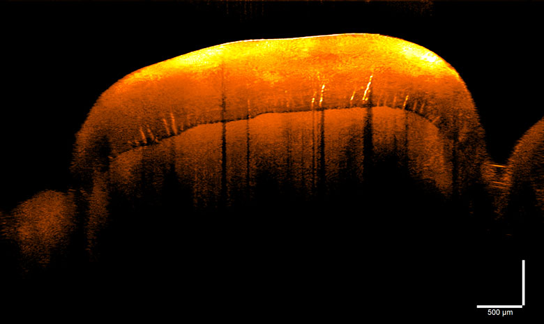
Figure 116V Despeckle Filter Applied to an OCT Image of a Human Tooth

Click to Enlarge
Figure 116U OCT Image of a Human Tooth
Analysis
ThorImageOCT includes several tools for convenient data analysis. The integrated marker tool measures distances, as well as the structure size. Additionally, this tool can be used to display the intensity profile of the OCT data across a line. For precise distance and thickness measurements, the refractive index of the material under investigation can be set.
Despeckle Filter
The Despeckle Filter is an optimized image filter to reduce speckle noise without blurring details of the imaged structure. It can be turned on and off for all acquired 2D images in the offline mode.
As shown in Figure 116V, the despeckle filter can be applied to an image to reduce speckle noise without blurring details of the imaged structure.
Click to Enlarge
Figure 116X The marker tool can be used to measure layer thickness.
Click to Enlarge
Figure 116W Surface Detection Tool
Marker Tool
The integrated marker tool serves to measures distances, as well as the structure size. Additionally, this tool can be used to display intensity profile of the OCT data across a line. For precise distance and thickness measurements, the refractive index of the material under investigation can be set.
Surface Detection
The Surface View performs a segmentation of the outer surface of the object viewed in the OCT section. The surface is then rendered with colors indicating the actual depth and can be filtered to reduce the effect of noise.
Feature Plugins
| Quick Links |
|---|
| Doppler Mode Speckle Variance Mode Polarization-Sensitive Modes Python User Interface for Processing |
Click to Enlarge
Figure 116Y Doppler Dataset Showing the Velocity of a Rotated Plastic Stick with Opposite Flow Directions.
Doppler Mode
Doppler OCT imaging comes standard with all OCT systems. In the Doppler mode, phase shifts between adjacent A-scans are averaged to calculate the Doppler frequency shift induced by particle motion or flow. The number of lateral and axial pixels can be modified to change velocity sensitivity and resolution during phase shift calculation. The Doppler images are displayed in the main window with a color map indicating forward- or backward-directed flow, relative to the OCT beam.
Click to Enlarge
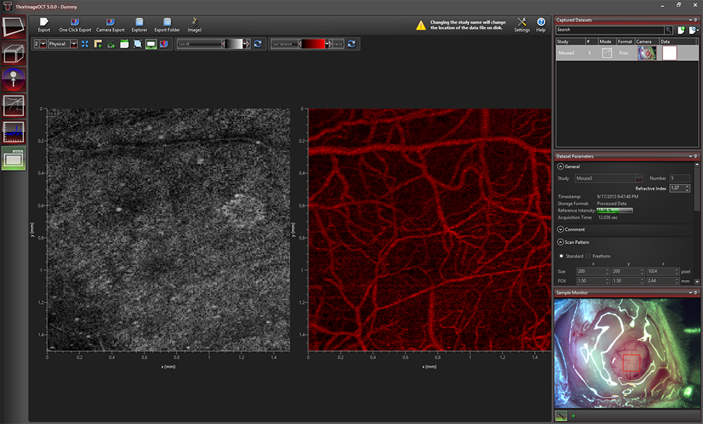
Figure 116Z Speckle Variance Measurement Showing Blood Vessels of a Mouse Brain.
Speckle Variance Mode
The speckle variance imaging mode is an acquisition mode that uses the variance of speckle noise to calculate angiographic images. It can be used to visualize three dimensional vessel trees without requiring significant blood flow and without requiring a specific acquisition speed window. The speckle variance data can be overlaid on top of intensity pictures providing morphological information. Different color maps can be used to display the multimodal pictures.
Polarization Sensitive
In the Polarization-Sensitive OCT (PS-OCT) system, two additional imaging modes are available, and the 1D mode is augmented to show each camera's spectra simultaneously. The combination of both cameras, and therefore the unique additional information of the PS-OCT system, is implemented in the 2D and 3D Polarization-Sensitive Imaging Modes.
Click to Enlarge
Figure 116AA Several A-Scans at a Single Point Over Time (M-Scan)
1D Mode
In this mode, single-point measurements can be made that provide spectral and depth information, as well as the ability to observe time-related sample behavior with an M-scan. For single-point measurements, the simultaneously acquired spectra of the two line scan cameras in the PS-OCT system are displayed separately.
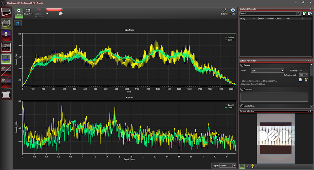
Click to Enlarge
Figure 116AB Spectral and Depth Information for a Single Point (A-Scan)
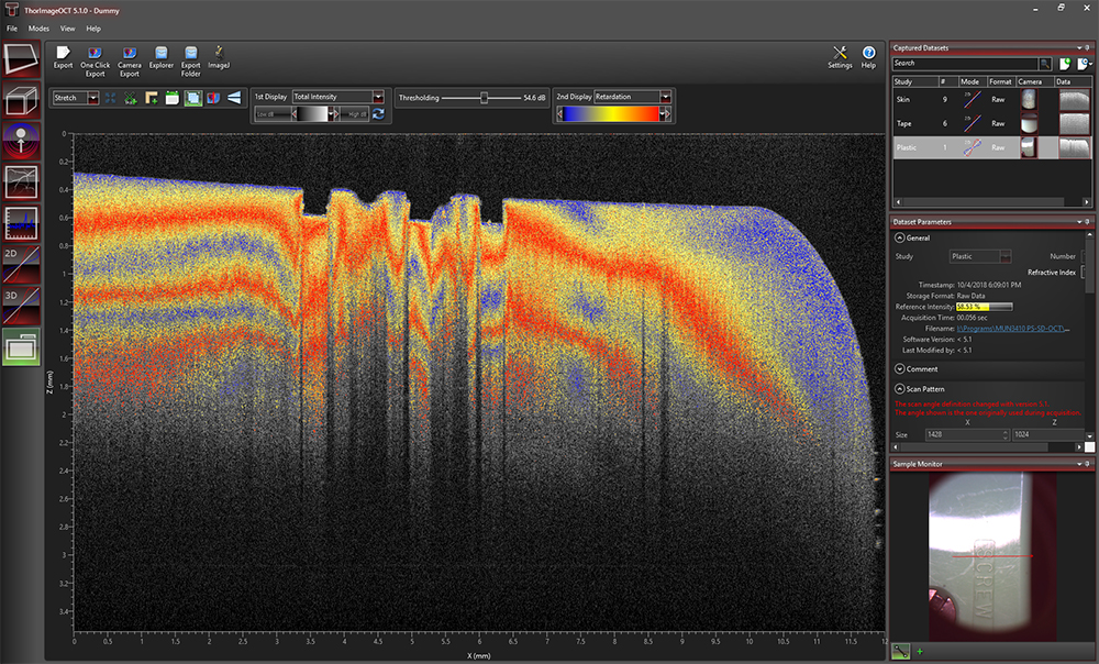
2D Polarization-Sensitive Mode
The 2D polarization-sensitive imaging mode acquires cross-sectional OCT images and displays them in real time. It has two configurable displays, each able to show one of the following images: a single camera's intensity, a combination of both cameras' intensities, or polarization data such as retardation, optic axis, DOPU or a single Stokes parameter. To improve the image quality or allow for variable acquisition time, several averaging parameters and adjustable line rates are implemented. Image display parameters, such as color mapping or thresholding, can be controlled in this mode. We have also implemented an option for automatic calculation of the optimum contrast, brightness, and thresholding of the displayed OCT images that operates on the intensity and PS-OCT images.
Click to Enlarge
Figure 116AC ThorImageOCT Window in 2D Polarization-Sensitive Mode
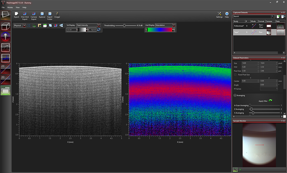
Click to Enlarge
Figure 116AD Dual Display Configuration of 2D Polarization-Sensitive Mode
Click to Enlarge
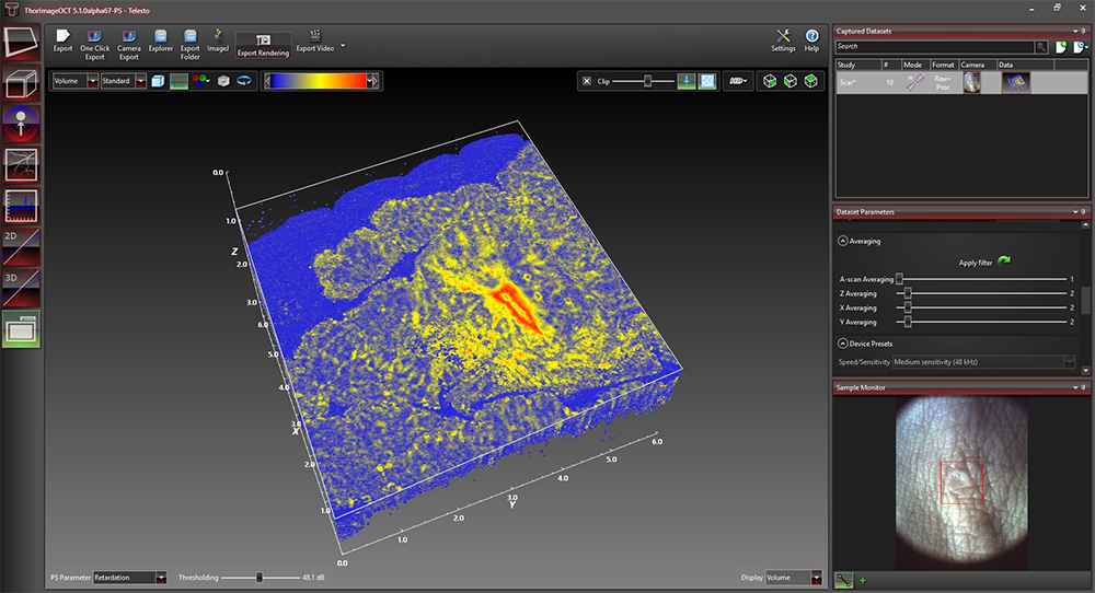
Figure 116AE The ThorImageOCT window in the 3D Polarization-Sensitive Mode
3D Polarization-Sensitive Mode
The 3D polarization-sensitive imaging mode extends the 3D imaging mode. The acquisition and display options are the same as in the 3D imaging mode. Additionally, the user can choose to display one of the following rendered volume imaging options: an intensity OCT image (from either a single camera or the combination of both) or a PS-OCT image (such as retardation, optic axis, DOPU or one of the three Stokes parameters). The rendered PS-OCT images can be adjusted with a threshold computed out of the intensity OCT image to only display the polarization-sensitive data of regions above the noise.
ThorImage OCT includes a Fast Volume Rendering mode, which provides a preview for high-resolution 3D acquisitions of intensity and PS-OCT images. In this mode, high-speed volume renderings can be displayed in real time, providing rapid visualization of samples in three dimensions.

Click to Enlarge
Figure 116AF Dataflow with Python Processing
Python User Interface for Processing
The Python Processing feature enables the advanced user to bypass the default signal processing routines and seamlessly integrate experimental/prototypical signal processing algorithms directly into the ThorImage environment. This provides utility both in the research (development of signal processing and analysis routines) and educational domains. Key features include:
- Write Customized Signal Processing Routines Using Python Syntax
- Utilize the Wide Array of Python Open-Source Signal Processing, Image Analysis, and Machine Learning Libraries
- Parameterize Algorithms and Routines
- Python Outputs and Debugging Messages Print Directly in ThorImage OCT
- Display Plots and Visualize Processing Steps with The Matplotlib Library
- Demo Implementations and Code Documentation Included
- Supports 1D, 2D, and 3D Imaging Modes of all Thorlabs OCT Systems (Excepting Doppler, Speckle Variance, and Polarization-Sensitive Imaging Modes)
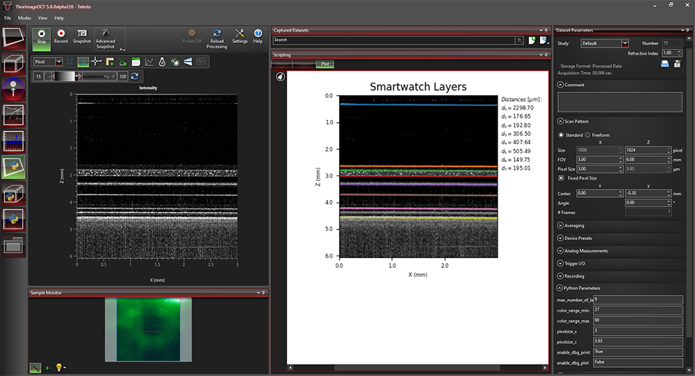
Layer Thickness Measurement
The Python Processing Interface also allows users to integrate customized post-processing algorithms for data modification or analysis. The demo program, shown in Figure 116AG, displays an OCT scan of the inner layers of a smart watch. By extending the signal processing algorithms with appropriate segmentation methods, the python processing feature can be used to highlight the individual layers and compute the distances in between.
Click to Enlarge
Figure 116AG Python Demo Program Post Processing Thickness Layer Measurement of a Smart Watch
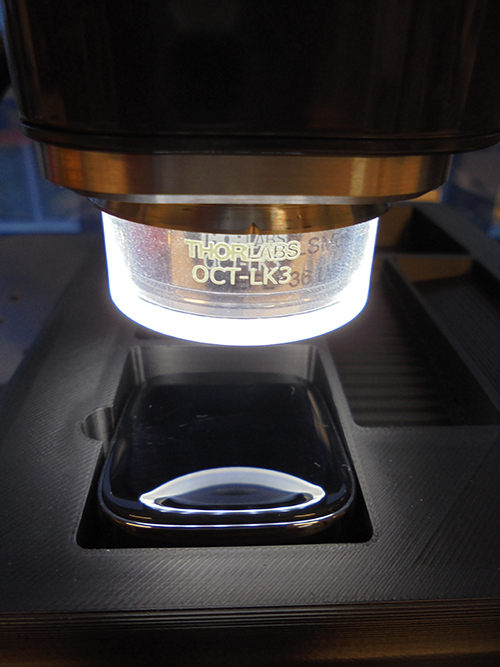
Click to Enlarge
Figure 116AH Smartwatch Under OCTG13 with OCT-LK3
Integration
| Quick Links |
|---|
| Data Export Hardware Synchronization Third-Party Integration Software Development Kits Custom Programming Options User Guide |
Data Export
Datasets can be exported in various image formats, such as PNG, BMP, JPEG, PDF, or TIFF. The set can also be exported in complete data formats suited for post-processing purposes, such as RAW/SRM, FITS, VTK, VFF, and 32-bit floating-point TIFF.
The OCT file format native to ThorImageOCT allows OCT data, sample monitor data, and all relevant metadata to be stored in a single file. ThorImageOCT can also be installed and run on computers without OCT devices in order to view and export OCT data. The user has full access to the raw and processed data from the device, including additional data used for processing, e.g. offset errors.
Click to Enlarge
Figure 116AJ Analog Data Visualization in the 2D Display
Hardware Synchronization
Externally-Triggered Acquisition
ThorImageOCT and the SDK APIs (in C, LabVIEW, and Python) provide the ability to externally trigger the acquisition of A-Scans. This enables the user to synchronize measurements from different modalities (e.g. vibrometry and synchronized positioning) with an OCT measurement. Synchronization is greatly simplified with all current CameraLink-based Thorlabs OCT systems (a TTL level trigger signal source is required). External triggering is available for all imaging modes and can be toggled in the settings dialog in ThorImageOCT.
Thorlabs' current generation of Ganymede and Telesto SD-OCT, and the Telesto PS-OCT Systems include an external B-Scan trigger for synchronization with other experiments.
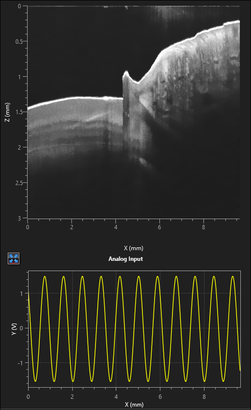
Analog Input for Synchronization with Other Modalities
Thorlabs' current generation of Ganymede and Telesto SD-OCT, and the Telesto PS-OCT Systems include two analog input channels, which can be used to combine imaging modalities. The analog signal from another data source (i.e., fluorescence signal) is sampled and displayed simultaneously with the OCT signal.
Third-Party Integration

Click to Enlarge
Figure 116AK Export buttons are accessible in the Action Toolbar of ThorImageOCT.
Link to ImageJ
If both ImageJ and ThorImageOCT are installed on the computer, opening acquired OCT data in ImageJ is one mouse click away. This enables a smooth workflow when requiring the advanced image processing functionality provided by ImageJ. Clicking the Explorer button will open the folder and select the file in Windows Explorer where the currently active dataset is stored.
External Program
Click to Enlarge
Figure 116AN After smoothing the data in ImageJ, the marker tool in ThorImageOCT can be used to measure layer thickness.
Click to Enlarge
Figure 116AM A filter for smoothing lateral directions is applied to the image in ImageJ.
Click to Enlarge
Figure 116AL OCT Data of a Plastic Multilayered Film with Speckle
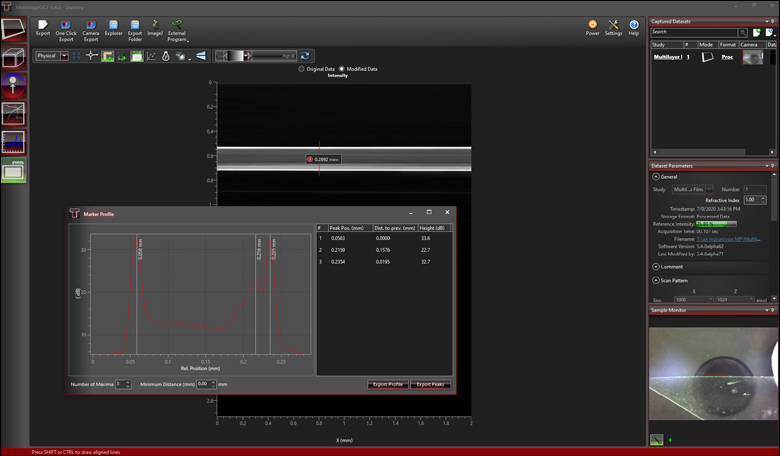
Acquired OCT datasets can also be exported and modified in a third-party program, and then reimported back into the ThorImageOCT software. This functionality allows fast and customized modifications of OCT images, while still using the dataset management of the ThorImageOCT software. As shown in Figures 116AL, 116AM, and 116AN, OCT data (Figure 116AL) can be exported to ImageJ and a smoothing filter applied in the lateral direction (Figure 116AM). Using the "External Program" button allows the modified data to be reimported into ThorImageOCT for further analysis. For example, the peak detection tool can be used to measure the layer thicknesses (Figure 116AN).
Python User Interface for Processing
The Python User Interface for Processing described in the Feature Plugins tab above enables user-development of customized processing routines, and allows for live display of these processing routines.

Click to Enlarge
Figure 116AP Available ThorImage Automation Functions Marked in Red from ThorImageOCT GUI in the 2D Acquisition Mode
Software Development Kits
Spectral Radar APIs
For maximum flexibility, customized solutions can be implemented in ThorImageOCT using software development kits (SDKs). Experienced software developers can use these in a multitude of programming environments to tailor the use of Thorlabs OCT systems to their specific application. SDKs are available in:
- ANSI C
- LabVIEW®
- Python
ThorImage Automation
ThorImage Automation is a light-weight API for performing OCT tasks through the ThorImageOCT GUI. This is in contrast to the SpectralRadar API, which communicates directly with the device. SpectralRadar offers large flexibility, whereas ThorImage Automation enables implementation of simple OCT task with a minimal amount of code.
ThorImage Automation is available in:
- C
- C#
- LabVIEW
- Python
Custom Programming Options User Guide
Table 116AQ provides guidance on choosing the right programming option for the user depending on the user requirements, programming experience and capabilities of the software.
| Table 116AQ ThorImage®OCT Programming Options User Guide | |||||
|---|---|---|---|---|---|
| SDK APIs | ThorImage Automation | Python Processing | External Program | ||
| Entry Point | User Program | User Program | ThorImageOCT GUI | ThorImageOCT GUI | |
| Flexibility/Limitation | Great Flexibility | Limited to Specific ThorImageOCT GUI Functionality | Limited to OCT Processing Functionality | Limited to OCT Post Processing Functionality | |
| Programming Level | Low Level | High Level with Very Little Code | Low Level (OCT Processing Only) |
Low-Medium Level (Post Processing Only) |
|
| Online/Offline | Full Control on User Side |
Online (Hook to Specific ThorImageOCT GUI Functions to the Code) |
Online (User Processing Code Used in ThorImageOCT GUI) |
Offline (Feature in ThorImageOCT GUI) |
|
| ThorImageOCT Running/Usable At the Same Time | No | Yes | Yes | Yes | |
| Software | C | Yes | Yes | No | Arbitrary Third-Party Software |
| C# | Via C-API | Yes | No | Arbitrary Third-Party Software | |
| LabVIEW | Yes | Yes | No | Arbitrary Third-Party Software | |
| Python | Yes | Yes | Yes | Arbitrary Third-Party Software | |
| Example User REquirements: Implementation of ... | User GUI | Yes | No | No | No |
| User OCT Processing | Yes | No | Yes | No | |
| User Post Processing | Yes | No | No | Yes | |
| Automation | Yes | Yes | No | No | |
| Recommended OCT Knowledge | Advanced | Beginner | Beginner | Beginner | |
| Rocommended OCT Processing Knowledge | Beginner | Beginner | Advanced | Beginner | |
Specifications
| ThorImage®OCT Specifications | ||
|---|---|---|
| General | Compatibility | |
| OCT Method |
|
|
| Imaging Modes |
|
|
| Operating System |
|
|
| Acquisition | Synchronization Options |
|
| Sample Monitor |
|
|
| Data Acquisition |
|
|
| Speed/Sensitivity |
|
|
| Scan Control |
|
|
| Averaging |
|
|
| Apodization |
|
|
| Probe Calibration |
|
|
| Processing | GUI |
|
| Python Processing Interface |
|
|
| Data Viewing | Common Options |
|
| 2D Mode |
|
|
| 3D Mode |
|
|
| Analysis | Native Tools |
|
| Third-Party Integration |
|
|
| File Handling | .oct Files | Full Access To:
|
| File Export |
|
|
| SDKs | Spectral Radar API |
|
| ThorImageAutomation |
|
|
| Settings | Workspace |
|
| Support | Technical Support |
|
For information on the availability of ThorImageOCT version 5.8, please contact our OCT Support Team.
Brochure and Configuration Chart
The buttons below link to PDFs of printable materials and a graphical customization guide for our Telesto® Series PS-OCT Systems.


Click to Enlarge
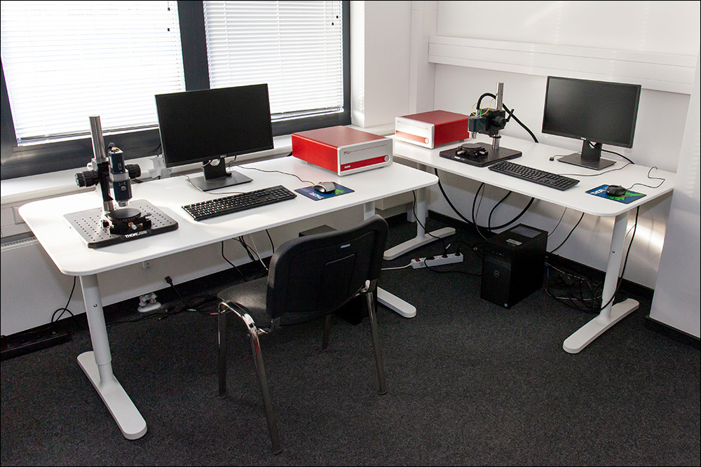
Figure 90A Lübeck Demo Room
Try Our OCT Imaging Systems In Person or Virtually
From our OCT facility in Lüebeck, Germany and offices in Virginia, USA; Tokyo, Japan; and Shanghai, China; Thorlabs' application specialists and sales engineers look forward to helping you determine the best OCT system to meet your specific experimental needs. We can provide tailored recommendations and partner with you to obtain images of your samples, demonstrating the impact of the OCT base unit and probe optics on image quality.
Thorlabs' worldwide network allows us to operate demo rooms in a number of locations where you can see our OCT systems in action. We welcome the opportunity to work with you in person or virtually. A demo can be scheduled at any of our showrooms or virtually by contacting OCT@thorlabs.com.
Demo Rooms and Customer Support Sites
(Click Each Location for More Details)
Lübeck, Germany
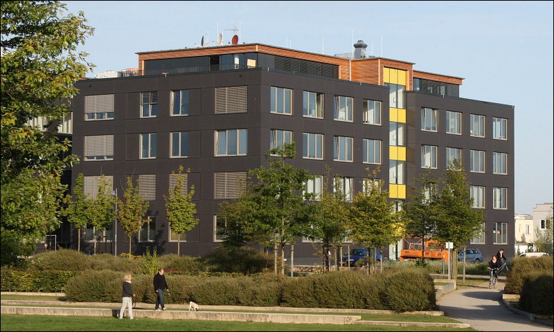
Thorlabs GmbH
Maria-Goeppert-Straße 9
23562 Lübeck
Customer Support
- Phone: +49 (0) 8131-5956-2
- Email: oct@thorlabs.com
Demo Rooms
- Ganymede® Series SD-OCT Systems
- Telesto® Series SD-OCT Systems
- Telesto® Series PS-OCT Systems
- Atria® Series SS-OCT Systems
- Vega™ Series SS-OCT Systems
Sterling, Virginia, USA
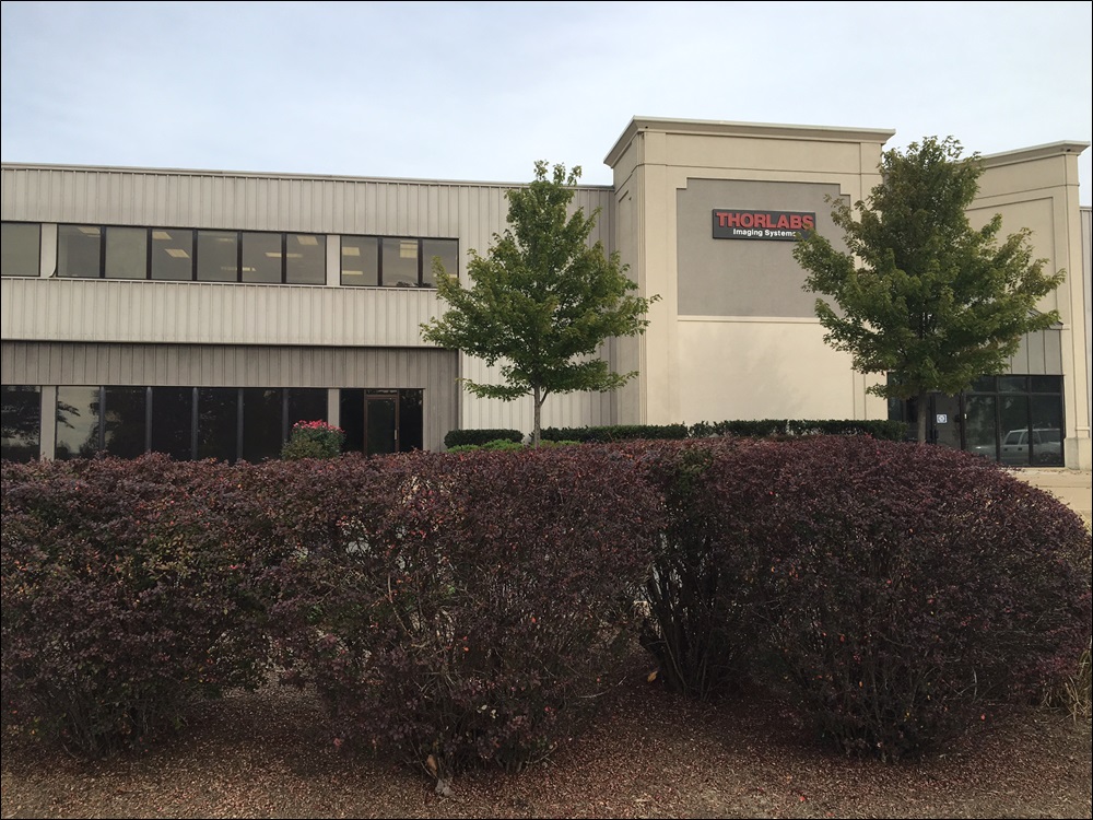
Thorlabs Imaging Systems HQ
108 Powers Court
Sterling, VA 20166
Customer Support
- Phone: (703) 651-1700
- E-mail: ImagingTechSupport@thorlabs.com
Demo Rooms
Nerima-ku, Tokyo, Japan
Thorlabs Japan, Inc.
3-6-3 Kitamachi
Nerima-ku, Tokyo 179-0081
Customer Support
- Phone: +81-3-6915-7701
- Email: sales@thorlabs.jp
Demo Rooms
Shanghai, China
Thorlabs China
Room A101, No. 100, Lane 2891, South Qilianshan Road
Shanghai 200331
Customer Support
- Phone: +86 (0)21-60561122
- Email: techsupport-cn@thorlabs.com
Demo Rooms
Customer Support Sites
(Click Each Location for More Details)
Newton, New Jersey, USA
Thorlabs HQ
43 Sparta Avenue
Newton, NJ 07860
Customer Support
- Phone: (973) 300-3000
- E-mail: techsupport@thorlabs.com
Ely, United Kingdom
Thorlabs Ltd.
1 Saint Thomas Place, Ely
Ely CB7 4EX
Customer Support
- Phone: +44 (0)1353-654440
- E-mail: techsupport.uk@thorlabs.com
Bergkirchen, Germany
Thorlabs GmbH
Münchner Weg 1
85232 Bergkirchen
Customer Support
- Phone: +49 (0) 8131-5956-0
- E-mail: europe@thorlabs.com
Puteaux, France
Thorlabs SAS
76 Route de la Demi Lune
92800 Puteaux
Customer Support
- Phone: +33 (0) 970 440 844
- E-mail: techsupport.fr@thorlabs.com
São Carlos, SP, Brazil
Thorlabs Vendas de Fotônicos Ltda.
Rua Rosalino Bellini, 175
Jardim Santa Paula
São Carlos, SP, 13564-050
Customer Support
- Phone: +55 (21) 2018 6490
- E-mail: brasil@thorlabs.com
Thorlabs offers a variety of OCT Imaging Systems to meet a range of application requirements. The OCT base unit and scan lens kit are key to OCT system performance. Significant performance characteristics, including axial resolution, A-Scan rate, and imaging depth, are entirely or strongly dependent on the design of the OCT base unit. The choice of scan lens kit determines other parameters, such as lateral resolution and field of view. Thorlabs offers a variety of OCT base units and scan lens kits that provide foundations for systems with a wide range of capabilities. The tables below present key performance parameters of our base units and include links to our other OCT imaging system pages. We encourage you to contact us directly at oct@thorlabs.com or via our online request form to discuss specific imaging requirements.
Swept Source OCT Base Units
| Base Unit Item #a | ATR206 | ATR220 | VEG210 | VEG220 |
|---|---|---|---|---|
| Series Name (Click for Link) | Atria® | Vega™ | ||
| Key Performance Feature(s) | Long Imaging Range | High Speed | Long Imaging Range | |
| High Resolution | General Purpose | High Speed | ||
| Center Wavelength | 1060 nm | 1300 nm | ||
| Imaging Depthb (Air/Water) | 20 mm / 15 mm | 6.0 mm / 4.5 mm | 11 mm / 8.3 mm | 8.0 mm / 6.0 mm |
| Axial Resolutionb (Air/Water) | 11 µm / 8.3 µm | 14 µm / 10.6 µm | ||
| A-Scan Line Rate | 60 kHz | 200 kHz | 100 kHz | 200 kHz |
| Sensitivity (Max)c | 102 dB | 97 dB | 102 dB | 98 dB |
Spectral Domain OCT Base Units
| Base Unit Item #a | GAN111 | GAN312 | GAN612 | GAN332 | GAN632 |
|---|---|---|---|---|---|
| Series Name | Ganymede® | ||||
| Key Performance Feature(s) | High Resolution | High Resolution | Very High Resolution | ||
| High Speed | Very High Speed | High Speed | Very High Speed | ||
| Center Wavelength | 880 nm | ||||
| Imaging Depthb (Air/Water) | 3.4 mm / 2.5 mm | 3.4 mm / 2.5 mm | 1.6 mm / 1.2 mm | ||
| Axial Resolutionb (Air/Water) | 6.0 µm / 4.5 µm | 6.0 µm / 4.5 µm | <3.0 µm / <2.2 µm | ||
| A-Scan Line Rate | 1.5 kHz to 20 kHz | 1.5 kHz to 80 kHz | 5 kHz to 248 kHz | 1.5 kHz to 80 kHz | 5 kHz to 248 kHz |
| Sensitivity (Max)c | 106 dB | 106 dB | 102 dB | 106 dB | 102 dB |
| Base Unit Item #a | TEL221 | TEL321 | TEL411 | TEL511 | TEL211PS | TEL221PS |
|---|---|---|---|---|---|---|
| Series Name (Click for Link) | Telesto® | Telesto® PS-OCT | ||||
| Key Performance Feature(s) | High Resolution | High Imaging Depth | High Imaging Depth | High Resolution | ||
| General Purpose | High Speed | General Purpose | High Speed | Polarization Sensitive-Imaging | ||
| Center Wavelength | 1300 nm | 1315 nm | 1325 nm | 1300 nm | ||
| Imaging Depthb (Air/Water) | 3.5 mm / 2.6 mm | 6.0 mm / 4.5 mm | 7.0 mm / 5.3 mm | 3.5 mm / 2.6 mm | ||
| Axial Resolutionb (Air/Water) | 5.5 µm / 4.2 µm | 11.0 µm / 8.3 µm | 11.0 µm / 8.3 µm | 5.5 µm / 4.2 µm | ||
| A-Scan Line Rate | 5.5 kHz to 76 kHz | 10 kHz to 146 kHz | 2.0 kHz to 120 kHz | 2.0 kHz to 240 kHz | 5.5 kHz to 76 kHz | 5.5 kHz to 76 kHz |
| Sensitivity (Max) | 111 dBc | 109 dBc | 114 dBd | 109 dBc | ||
| Posted Comments: | |
Massimo Olivero
(posted 2023-12-01 11:06:02.987) Dear Sir,
I would like to know whether it is possible to calculate the Mueller matrix layer by layer with the PS-OCT and if this information is directly give by the software.
Thank you in advance.
M jweimar
(posted 2023-12-11 03:14:37.0) Dear Massimo, thank you for your feedback. The software does not calculate the Mueller matrix and will only give the Stokes parameters, the cumulative retardation, optic axis, and DOPU. Please see the "PS-OCT Tutorial" tab for more details. Sejong Chun
(posted 2020-01-22 21:06:57.037) I'm Sejong Chun, working at the Fluid Flow Group in KRISS, South Korea. (It is a metrology institute in South Korea.)
I would like to just learn whether such an OCT system can measure flow velocity as well as fluid viscosity.
1) flow velocity measurement in a micro channel
2) fluid viscosity measurement in the micro channel with Non-Newtonian fluids (shear thinning and shear thickening fluids) by birefringence.
Thank you for your kind comments. nreusch
(posted 2020-01-28 05:33:58.0) Dear Sejong Chun,
Thank you for your provided feedback. In the following, we will reply on your specific questions:
1.) In fact, our OCT systems are able to measure flow velocities of fluids via the functional Doppler Acquisition Mode that is included within our OCT software application.
2.) The TEL220PSC2 OCT system can visualize birefringent layers, e.g. by determining the phase retardation between two orthogonally polarized states of the back-scattered OCT light.
Please do not hesitate to contact us at OCT@thorlabs.com, if you have any further questions.
Best regards,
Your Thorlabs OCT Applications Team |

 Zoom
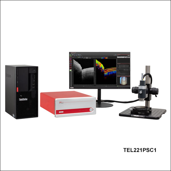
Zoom- Complete Preconfigured 1300 nm or 1325 nm OCT Systems (See Tables G1.1 and G1.2)
- Item # TEL211PSC1(/M): Long-Range Imaging
- Item # TEL221PSC1(/M): General-Purpose Imaging
- Customizable Using Other Telesto® Series Components
- Fully Configurable Trigger for Easy Integration into Larger Experiments
- Analog Input for Combining Other Data Sources with the OCT Signal
- Internal Hardware Diagnostics for Improved Troubleshooting
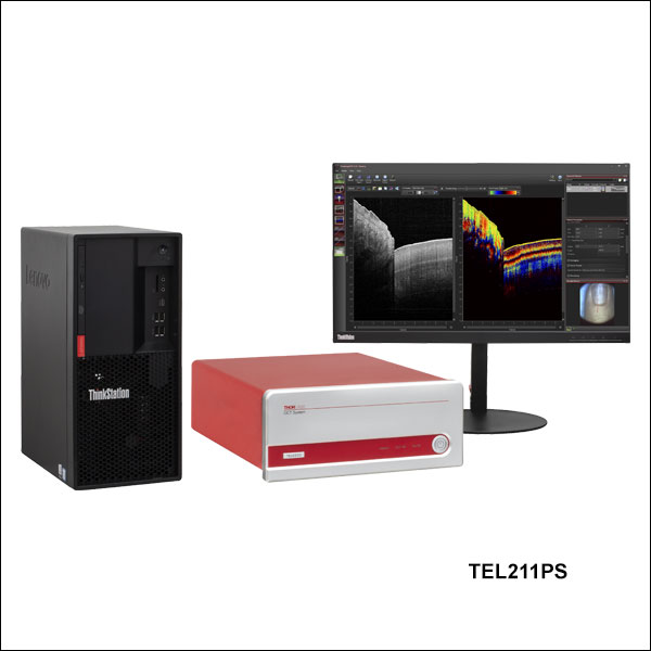
Thorlabs offers two complete, preconfigured Telesto PS-OCT systems, which include a specialized scanner that was exclusively developed for polarization-sensitive OCT imaging. The TEL211PSC1(/M) system has a 1325 nm center wavelength with a large imaging depth. The TEL221PSC1(/M) system features a center wavelength of 1300 nm and is designed for general-purpose imaging applications. Both systems feature a maximum A-Scan rate of 76 kHz.
These Telesto Series preconfigured OCT system configurations are built completely from components sold in sections located lower on this page. Each preconfigured system includes the three OCT system core components (the base unit, a scanning system with its reference length adapter, and a scan lens kit), as well as two optional accessories (scanner stand and translation stage). For more information about a component included in the preconfigured systems, click on the component description in Table G1.1 to navigate down to the related section on this page.
For information about these systems or to inquire about custom configurations, please contact oct@thorlabs.com.
| Table G1.1 Preconfigured System Included Componentsa | |||
|---|---|---|---|
| System Item # | TEL211PSC1(/M) | TEL221PSC1(/M) | |
| Base Unit | TEL211PS | TEL221PS | |
| Scanning System | OCTG13PS (Standard Scanner) | ||
| Scan Lens Kit | OCT-LK4 | OCT-LK3 | |
| Reference Length Adaptor | OCT-RA4 | OCT-RA3 | |
| Accessories: Scanner Stand and Translation Stage |
Imperial | OCT-STAND (Stand) and OCT-XYR1 (Stage) |
|
| Metric | OCT-STAND/M (Stand) and OCT-XYR1/M (Stage) |
||
| Table G1.2 Preconfigured System Key Specifications | ||
|---|---|---|
| System Item # | TEL211PSC1(/M) | TEL221PSC1(/M) |
| Imaging Depth (Air/Water) | 7.0 mm / 5.3 mm | 3.5 mm / 2.6 mm |
| Axial Resolution (Air/Water) | 11 µm / 8.3 µm | 5.5 µm / 4.2 µm |
| Lateral Resolution | 20 µm | 13 µm |
| A-Scan/Line Rate | 5.5 - 76 kHza | |
| Sensitivity (Max)b | 109 dB (at 5.5 kHz) | |
")
 Zoom
Zoom
To be functional, an OCT system build must include a base unit, a scanning system, and a scan lens kit.
- 1300 nm or 1325 nm Center Wavelength Options
- 1300 nm, High Resolution: 3.5 mm Imaging Depth and 5.5 µm Resolution in Air
- 1325 nm, Long Range: 7.0 mm Imaging Depth and 11 µm Resolution in Air
- Each Base Unit has Four A-Scan Rates for Flexibility in Imaging Speed and Sensitivity
- 5.5 kHz to 76 kHz A-Scan Rate; 109 dB Max Sensitivity
- Fully Configurable Trigger for Easy Integration into Larger Experiments
- Analog Input for Combining Other Data Sources with the OCT Signal
- Internal Hardware Diagnostics for Improved Troubleshooting
The imaging performance of any OCT system is largely dependent on the design and components incorporated into the base unit. All of Thorlabs' OCT base units include an OCT engine, high-performance computer, pre-installed software, and a software development kit (SDK). For a fully operational system, one scanning system and a scan lens kit (both sold separately below) must be purchased along with a base unit.
For the Telesto® Polarization-Sensitive OCT Base Units, the engine is comprised of a superluminescent diode light source, scanning electronics, and a polarization-sensitive detection module (see the PS-OCT Tutorial for more information). These base units are capable of operating at A-Scan rates up to 76 kHz and offers a maximum sensitivity of 109 dB at 5.5 kHz. The engine and detection components are integrated into a 411.8 mm x 325.0 mm x 143.0 mm (16.21" x 12.80" x 5.63") housing.
For synchronization with other experiments, two analog inputs are included on the base units; this allows other data sources to be combined or overlayed with the OCT signal. The OCT base units also feature a fully configurable trigger that is extensively programmable in our ThorImage®OCT software. The trigger can be operated as either an input, responding to external signals, or an output, generating trigger signals. Trigger signals can be sent at the start of each A-, B-, or volume scan, as well as after an arbitrary number of scans.
Deep-Imaging Base Unit
The TEL211PS Deep-Imaging Base Unit is designed using an SLD1325 superluminescent diode that provides over 100 nm of spectral bandwidth and enables the base unit to achieve a very high 7.0 mm imaging depth with 11 µm of axial imaging resolution in air. For these reasons, this base unit is the ideal choice for long-range imaging of highly-scattering samples in an air medium.
High-Resolution Base Unit
The TEL221PS High-Resolution Base Unit features Thorlabs' highest resolution OCT imaging capability at 1300 nm. An ideal choice for high-resolution imaging in scattering samples, these base units utilize Thorlabs' unique matched-pair superluminescent diodes for over 170 nm of bandwidth that translates to 5.5 μm axial resolution at an imaging depth of 3.5 mm in air.
| Base Unit Item # | TEL211PS | TEL221PS |
|---|---|---|
| Description | Long-Range Imaging | High-Resolution Imaging |
| Center Wavelength | 1325 nm | 1300 nm |
| Imaging Depth (Air/Water) | 7.0 mm / 5.3 mm | 3.5 mm / 2.6 mm |
| Axial Resolution (Air/Water) | 11 µm / 8.3 µm | 5.5 µm / 4.2 µm |
| A-Scan Line Rate | 5.5, 28, 48, & 76 kHz | |
| Sensitivitya | 94 dB (at 76 kHz) to 109 dB (at 5.5 kHz) | |
| Maximum Pixels per A-Scan | 1024 | |
| Compatible Scanners | OCTP-1300PS, OCTP-1300PS/M, OCTG13PS | |
| Computer Specificationsa | |
|---|---|
| Operating System | Windows® 11 |
| Processor | 8 Core, 3.0 GHz |
| Memory | 64 GB |
| Hard Drive | 512 GB SSD |
| Data Acquisition | Camera Link |
Click to Enlarge
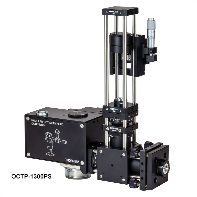
Figure G3.2 User-Customizable OCT Scanner
Click for Details
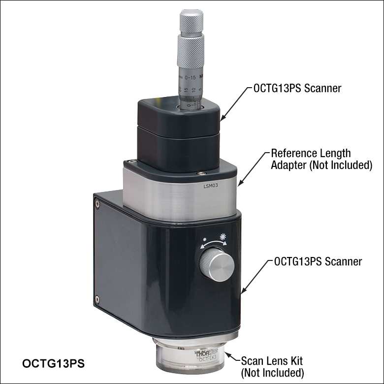
Figure G3.1 Standard OCT Scanner with Scan Lens Kit and Reference Length Adapter (Not Included)
| Scanner Type | Item # | Compatible Base Units |
|---|---|---|
| Standard Scannera | OCTG13PS | TEL211PS TEL221PS |
| PS-OCT User-Customizable Scanner |
OCTP-1300PS(/M) |
To be functional, an OCT system build must include a base unit, a scanning system, and a scan lens kit.
- Scan an OCT Light Source Beam Across a Sample to Acquire 2D or 3D Images
- Two Available Options:
- Standard Scanner for High Stability and Ease-of-Use
- User-Customizable Scanner with Open Construction for Customization of Scan Path
OCT scanning systems scan the OCT light source beam across a sample for 2D cross-sectional and 3D volumetric imaging. OCT applications can vary widely, from live animal imaging to industrial materials analysis, with each requiring a different set of scanning parameters. We currently offer two types of beam scanning systems for use with our Telesto® polarization sensitive base units: standard and user-customizable.
Each scanner contains an OCT interferometer with a sample arm and a reference arm. The reference arm of the OCT interferometer is placed near the sample and housed within the scanning system itself to guarantee the phase stability of the sample arm relative to the reference arm. To account for different sample distances and reflectivities (e.g., while imaging through water), the reference arm path length, as well as the reference arm intensity, is user-adjustable. To minimize image distortion caused by dispersion, our OCT systems are designed to optically match the reference and sample arm lengths to the greatest extent possible. Dispersion effects from the sample (e.g., imaging through water or glass) can be compensated for using the included ThorImage OCT software.
The scanner is equipped with an integrated camera that can obtain real-time en face video of the sample during OCT measurements when used with our ThorImage OCT software (see the Software tab for details). Illumination of the sample is provided by a ring of user-adjustable white light LEDs around the exit aperture of each scanner.
The specialized PS-OCT scanners contain two additional quarter-wave plates (compared to the SD-OCT scanners), which are necessary to obtain polarization images. Since the interference of light depends on its polarization state, it is necessary to change the polarization state of the light in the reference arm to be sensitive to all possible polarization states of the light in the sample arm. Hence, one quarter-wave plate is located in the reference arm and a second quarter-wave plate is located in the sample arm to create a polarization state which leads to a maximum contrast in the polarization images. Please see the PS-OCT Tutorial tab for more details.
PS-OCT Standard Scanner
The OCTG13 PS-OCT Standard Scanner is ideal for imaging applications that require a stable, easy-to-operate setup. The entire design of the standard scanner is contained within a rugged, light-tight housing that minimizes the risk of misalignment. For precise measurements and fine adjustments of the reference arm length, a micrometer screw is located at the top of the standard scanner. A reference length adapter, which must be purchased separately, is required for this scanner.
PS-OCT User-Customizable Scanner
The OCTP-1300PS(/M) User-Customizable Scanner is designed with an open construction to enable easy customization of the optical beam path using Thorlabs' standard optomechanical components. This scanner features SM1 (1.035"-40) ports and 4-40 tapped holes at several locations that allow mounting of SM1-threaded or 30 mm cage-compatible components, respectively. The scan lens port is directly compatible with either M25 x 0.75 or SM1-threaded components, and can be converted to other thread standards, such as RMS (0.800"-36) via our selection of thread adapters. Additional scanning and non-scanning optical input/output ports are available for integration of a laser for fluorescence excitation or additional sample illumination.
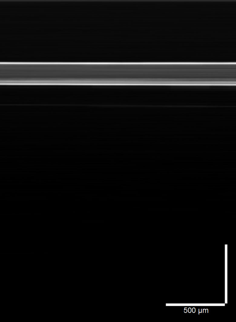
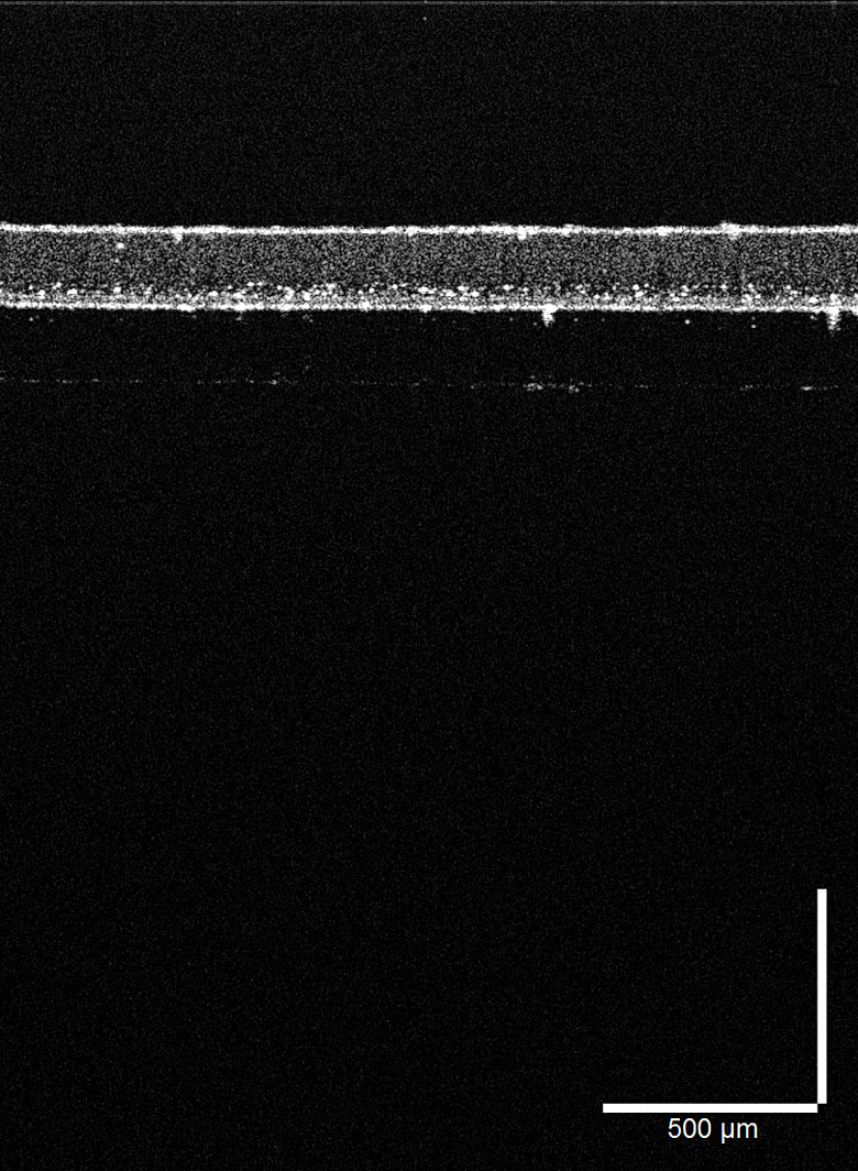
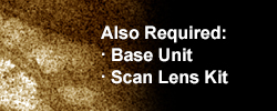
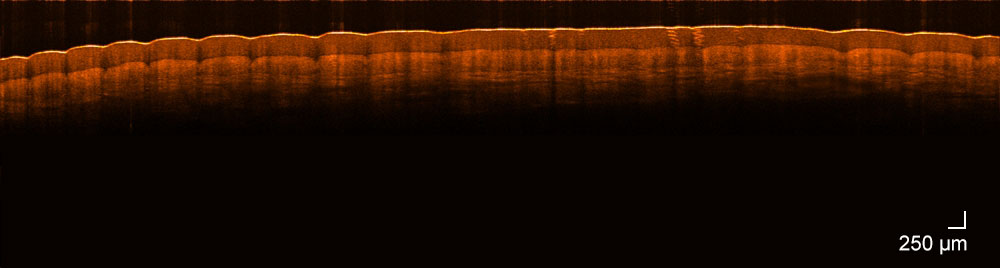
The cross sectional images of a finger pad, shown here, were taken with a Telesto® Series OCT system fitted with the OCT-LK2 (Figure G4.1) and OCT-LK4 (Figure G4.2) scan lens kits. The selection of available Telesto series components offer significant flexibility in building an OCT system optimized for your application.
Click to Enlarge
Figure G4.2 OCT-LK4 Deep Imaging
Magnification: 3X
Scan Region: 16 mm x 3.5 mm
Lateral Resolution: 20 µm
Click to Enlarge
Figure G4.1 OCT-LK2 High Resolution
Magnification: 10X
Scan Region: 6 mm x 3.5 mm
Lateral Resolution: 7 µm
 To be functional, an OCT system build must include a base unit, a scanning system, and a scan lens kit.
- Telecentric Scan Lenses Provide Flat Imaging Plane
- Lens AR Coated for 1315 ± 65 nm
- Scan Lens Kits Include:
- Telecentric Scan Lens
- Illumination Tube
- IR Card
- Calibration Target
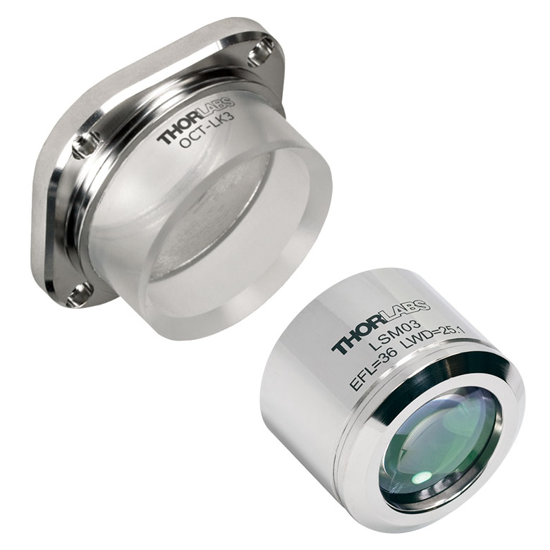
Thorlabs' Scan Lens Kits enable easy exchange of scan lenses in an OCT system, providing the flexibility to tailor imaging resolution or working distance for each application. Based on our line of OCT telecentric scan lenses, these lens kits minimize image distortion without extensive post-image processing and maximize coupling of the light scattered or emitted from the sample surface into the detection system. As seen in Table G4.3, we offer scan lens kits compatible with the standard (Item # OCTG13PS) and user-customizable (Item # OCTP-1300PS) scanners.
Each kit includes a telecentric scan lens, illumination tube, IR card, and calibration target. The included illumination tube serves as a light guide that channels light from the LED illumination ring down to the sample area. The IR card and calibration target are provided for calibration of the scanning mirror and lens kit, ensuring the best image quality when swapping between scan lenses.
| Table G4.3 Specifications | |||
|---|---|---|---|
| Item # | OCT-LK2 | OCT-LK3 | OCT-LK4 |
| Click Image to Enlarge | 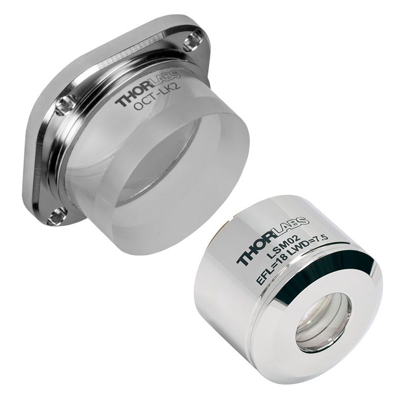 |
 |
 |
| Design Wavelength | 1315 nm | ||
| Compatible Scanner | OCTG13PS (Standard) or OCTP-1300PS(/M) (User-Customizable) | ||
| Lateral Resolutiona | 7 µm | 13 µm | 20 µm |
| Effective Focal Length | 18 mm | 36 mm | 54 mm |
| Working Distance | 3.4 mm (with Tube)b 7.5 mm (without Tube) |
24.9 mm (with Tube)b 25.1 mm (without Tube) |
41.6 mm (with Tube)b 42.3 mm (without Tube) |
| Field of View | 6 mm x 6 mm | 10 mm x 10 mm | 16 mm x 16 mm |
| Lens Threading | M25 x 0.75 | M25 x 0.75 | M25 x 0.75 |
")
 Zoom
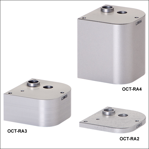
Zoom| Table G5.1 Compatibility | |
|---|---|
| Item #a | Compatible Scan Lens Kit |
| OCT-RA2 | OCT-LK2 |
| OCT-RA3 | OCT-LK3 |
| OCT-RA4 | OCT-LK4 |
- Arm Adapters for Matching Reference Path Length to the Sample Path Length
- Use Multiple Reference Adapters for Rapid Switching Between Scan Lens Kits
- Must be Purchased with Standard Scanner (Item # OCTG13PS)
These adapters adjust the reference arm path length within the OCTG13PS Standard Scanner to match the sample path length of the scan lens used. Choose from three options that are compatible with the scan lens kits sold above. Reference length adapters also enable the user to quickly swap between different scan lens kits without going through extensive adjustments during each switch. Table G5.1 provides a compatibility list to help select the appropriate reference adapters.
Click to Enlarge
Z-Spacers for the OCTP-13300PS(/M) and OCTG13PS Scanners
- Sample Z-Spacers Position Scanner at Optimal Working Distance From Sample
- Ring (Air) and Immersion (Liquid) Z-Spacers Available
Thorlabs offers both ring and immersion style sample Z-spacers that enable optimal positioning of a scanning system relative to the sample. The OCT-AIR3, OCT-IMM3, and OCT-IMM4 Z-Spacers feature knurled rings that allow the spacing distance to be adjusted and locked in place for increased stability. Several Z-spacer options are available; please see Table G6.1 for compatibility with our scanners and lens kits.
Our ring-style Z-spacers provide a distance guide between the scanner and sample. The sample is in contact with the ring-shaped tip of the spacer and should only be used when air is the scanning medium. In contrast, our immersion spacers are equipped with a glass plate that contacts the sample surface within the scanning area. Unlike the ring-style spacers, immersion spacers enable access to samples contained within a liquid environment while also providing sample stabilization. Better index matching and a tilted glass plate also help reduce strong back reflections from the sample surface and enhances the contrast of the image.
| Table G6.1 Compatibility | ||||||
|---|---|---|---|---|---|---|
| Item # | Type | Adjustable | Adjustment Range | Lockable | Compatible Scanner |
Compatible Scan Lens Kit |
| OCT-AIR3 | Ring (Air) | Yes | +3.5 mm / -1.0 mm | Yes | OCTG13PS OCTP-1300PS(/M) |
OCT-LK3 |
| OCT-IMM3 | Immersion | Yes | +3.4 mm / -1.1 mm | Yes | ||
| OCT-IMM4 | Immersion | Yes | +1.0 mm / -17.0 mm | Yes | OCT-LK4 | |
")
 Zoom
Zoom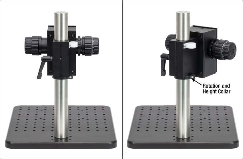
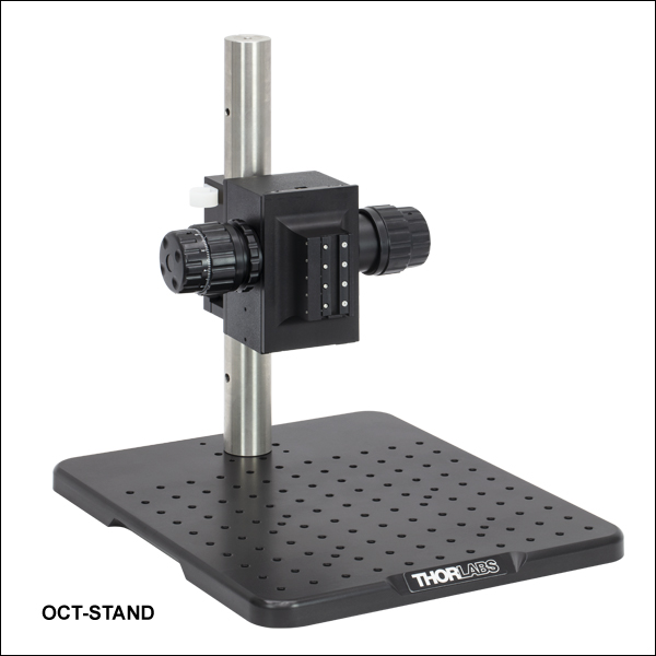
Click for Details
Figure 821A The focus block can be rotated 45° to move the scanner head away from the sample.
- Recommended Stand for Mounting Standard or User-Customizable Scanners
- Focus Block with Coarse/Fine Z-Axis Travel on Ø1.5" Stainless Steel Post
- 12" x 14" (300 mm x 350 mm) Aluminum Breadboard with 1/4"-20 (M6) Tapped Holes
For convenient mounting of our Standard or User-Customizable Scanners, we offer a scanner stand that is ideal for use in vibration-sensitive studies such as angiography. It consists of a post-mounted focus block with knobs that provide both coarse (40 mm/rev) and fine (225 µm/rev) z-axis travel. A rotation and height collar underneath the focus block allows it to rotate 45° in order to move the scanner head away from the sample to make adjustments.
The focus block attaches to a 12" x 14" (300 mm x 350 mm) aluminum breadboard via the included Ø1.5" post. The aluminum breadboard has side grips and rubber feet for easy lifting and transportation. There is an array of 1/4"-20 (M6) tapped holes for mounting optomechanics. Four extra 1/4"-20 (M6) tapped holes allow the mounting of the OCT-XYR1 Translation Stage (sold below) to the OCT-STAND and the OCT-XYR1/M Translation Stage to the OCT-STAND/M directly underneath the scan lens. A 1/4"-20 (M6) counterbore is also provided for securing the Ø1.5" post.
")
 Zoom
ZoomClick to Enlarge
Figure G8.1 The cover plate is removable for access to tapped holes and the SM1-threaded central hole.
| Specifications | |
|---|---|
| Horizontal Load Capacity (Max) | 10 lbs (4.5 kg) |
| Mounting Platform Dimensions | Ø4.18" (Ø106 mm) |
| Stage Height | 1.65" (41.8 mm) |
| Linear Translation Range | 1/2" (13 mm) |
| Travel per Revolution | 0.025" (0.5 mm) |
| Graduation | 0.001" (10 µm) per Division |
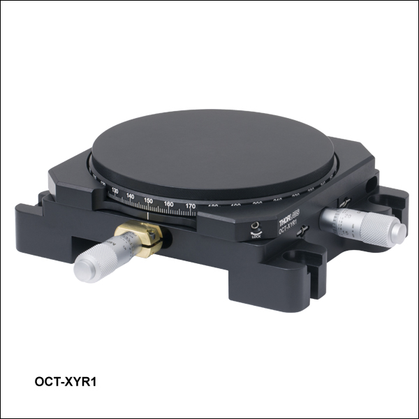
- Optional Translation Stage with 0.5" (13 mm) of XY Travel and 360° Rotation
- Includes Cover Plate for Sample Mounting
- Can Mount Optomechanics by Removing Cover Plate
Precise translation and rotation are often required for optimal positioning of a sample before and during OCT imaging. The OCT-XYR1(/M) is an XY linear translation stage with a rotating platform and solid plate for sample mounting and easy cleaning. The OCT-XYR1 or OCT-XYR1/M stage can be secured to the OCT-STAND or OCT-STAND/M, respectively, using the 1/4" (M6) counterbores at the corners. The top plate is removable for access to 4-40, 8-32 (M4), and 1/4"-20 (M6) tapped holes and an SM1-threaded (1.035"-40) central hole for mounting optomechanical components. The XYR1A Solid Sample Plate can be purchased separately as a direct replacement for the top plate.
The X and Y micrometers offer 1/2" (13 mm) of travel with graduations every 0.001" (10 µm). The stage's rotation and translation can be freely changed without compromising the stability of attached components. An engraved angular scale along the outer edge of the stage's rotating platform allows the user to set the angular orientation of the stage, which can then be fixed using the 5/64" (2 mm) hex locking setscrew. Locking the rotation of the stage does not prevent XY translation using the actuators.