 Products Home
Fast Laser Power Modulators for Two-Photon Microscopy
- Pockels Cell and Acousto-Optic Modulator Alternative
- Broad Wavelength Coverage from 700 nm to 1350 nm Available
- Photoactivation Control Up to 500 nJ
- Near-Zero Dispersion Reduces Need for Pre-Compensation
OM6ENH
>2500:1 Contrast Ratio,
700 - 1350 nm
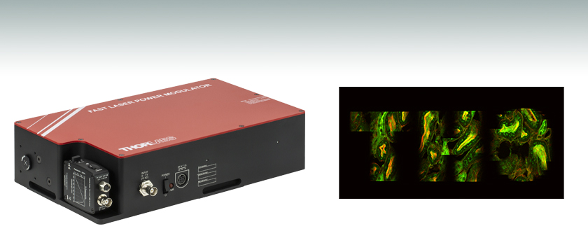
Two-channel 2P image of mouse kidney cells acquired with Thorlabs' Bergamo® III microscope using the OM6N fast laser power modulator to define a region of interest.


Please Wait

Click to Enlarge
Figure 1.1 Typical transmissions for the OM6N (solid), OM6NH (dotted), and OM6ENH (dashed) modulators at 700 nm (blue traces), 1100 nm (red traces), and 1300 nm (green trace). For each unit, the full transmission (at 0 V) differs with wavelength due to the reflective nature of the gold-coated mirrors. Additional performance graphs are available on the Graphs tab.
Applications
- Fast Power Modulation of NIR Femtosecond Lasers
- Two-Photon Fluorescence Microscopy
- Photoactivation
- Galvo-Galvo or Galvo-Resonant Scanning
- Edge and Frame Blanking
- Region of Interest Selection

Click to Enlarge
Figure 1.2 Our fast laser power optical modulator shown with the included photodetector removed, providing access to four 4-40 taps for 30 mm cage system compatibility.
Features
- Offers DC Power Attenuation and High-Speed Modulation
- Full Extinction AC Modulation Up to 200 kHz
- Supports Region of Interest Selection, Edge Blanking, and Frame Blanking in Imaging Systems
- Pockels Cell Alternative with Polarization-Independent Performance
- Intelligent Electronic Driving for Smooth Optical Response and Arbitrary Trajectory Tracking
- 700 - 1100 nm or 700 - 1350 nm Operating Ranges
- <1 µs On/Off Time
- Contrast Ratios Up to 2500:1
- Compatible with ThorImage®LS and ScanImage Software
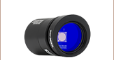
- Photodetector Included for Monitoring/Calibrating Output Power
- Near-Zero (<100 fs2) Dispersion
- Passively Cooled to Eliminate Vibrations
Thorlabs' Fast Laser Power Modulators use deformable mirror technology to provide high-speed intensity modulation and beam attenuation. The all-reflective design incorporates gold-coated MEMS mirrors that are polarization independent and introduce minimal (<100 fs2) dispersion. This unidirectional device is designed for a collimated, 1 to 2 mm (1/e2) diameter input beam with up to 10 W of optical power and up to 500 nJ of pulse energy, enabling use with popular 1 µm high-pulse-energy photoactivation lasers. These modulators are available with either standard (>250:1) or high (>2500:1) contrast ratios for wavelength ranges of 700 - 1100 nm or 700 - 1350 nm (high contrast only).
Transmission, which is a function of both input voltage and wavelength as shown in Figure 1.1, is controlled by a 0 to 1 V analog input voltage; this voltage can be easily generated by off-the-shelf data acquisition (DAQ) hardware or other electronics. The device supports continuous DC operation as well as modulation frequencies up to 200 kHz, making it ideal for imaging applications such as fly-back blanking or region of interest (ROI) selection.
The higher contrast achieved with the OM6NH(/M) and OM6ENH(/M) modulators is made possible by incorporating two MEMS mirrors, the deformation of which behaves like a grating, into the design; one diffracts horizontally and the other vertically to provide enhanced contrast performance.
Ideal for Photoactivation and Two-Photon Fluorescence Applications
These modulators are suitable for many applications including two-photon fluorescence microscopy and photoactivation. Both of these techniques require fast laser power modulation of ultrafast NIR laser pulses to limit sample exposure during imaging and reduce thermally induced damage. High-speed modulation is traditionally accomplished with bulk crystal modulators, such as Pockels cells and acousto-optic modulators (AOMs). As they rely on bulk materials, they introduce significant dispersion, degrading image quality.
Replaceable Photodetector
An internal beam sampler directs a small portion (<1%) of the modulated beam to a separate output port where a photodetector can be used to monitor the transmission. If desired, the included, pre-installed detector can be easily removed and replaced with a user-supplied detector; to do so, loosen the 8-32 mounting screw located on the underside of the modulator using a 9/64" hex key. The OM6N(/M) and OM6NH(/M) modulators each include a PDA100A2 detector, while the OM6ENH(/M) modulator includes a PDA20C2 detector.
Housing and Mounting Features
The input and output ports of each laser power modulator feature internal SM05 (0.535"-40) threading, which can be used to install external SM05-threaded alignment targets or irises (not included). All three ports also have 4-40 threaded holes for compatibility with our 30 mm cage systems. To aid in initial alignment, we recommend using an SM05 slotted lens tube or a 30 mm cage system assembly on the modulator input.
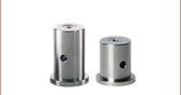
Three slots in the enclosure allow the modulator to be mounted directly to an optical table with table clamps, such as our CL6 clamps (not included), resulting in a minimum beam height of 1.25". The base also includes three 8-32 (M4) mounting holes for attaching pedestal posts, which can be used to elevate the modulator to the desired beam height.
The unit is shipped with a 24 V power supply with an KPJX-4S-S connector for the modulator, as well as a ±12 V supply for the photodetector. For more information, please see the Pin Diagrams tab.
Figure 2.1 Laser Power Modulator Housing Dimensions
| Item # | OM6N(/M) | OM6NH(/M) | OM6ENH(/M) |
|---|---|---|---|
| Contrast Ratio | >250:1 | >2500:1 | >2500:1 |
| Operating Rangea | 700 - 1100 nm | 700 - 1350 nm | |
| Included Photodetector | PDA100A2 | PDA20CS2 | |
| Input Polarization | Any | ||
| Rise/Fall Timeb | <1 µs | ||
| Modulation Frequencyc | 0 - 200 kHz | ||
| Small Signal Modulation Bandwidth (-3 dB) | >1 MHz | ||
| Insertion Delayd | <5 µs | ||
| Modulation Voltagee | 0 - 1 V | ||
| Input Impedancee | 10 kΩ | ||
| Transmission (@ 800 nm) | >80% | ||
| Input Pulse Energy | 500 nJ (Max) | ||
| Input Optical Power | 10 W (Max) | ||
| Internal Aperture | Ø3.8 mm | ||
| Recommended Collimated Input Beam Diameter (1/e2) |
Ø1 - 2 mm | ||
| Internal Optical Path Length | 100 cm | ||
| Dispersion | <100 fs2 | ||
| Transmitted Wavefront Errorf | <λ/4 (at 633 nm) | ||
| Power Supply | 24 V, 1 A | ||
| Power Connector | R7B Female Connector | ||
| Operating Temperature | 15 - 35 °C | ||
| Operating Humidity | 20 - 60% | ||
| Storage Temperature | -25 - 70 °C | ||
| Housing Dimensions (L x W x H) | 11.45" x 6.83" x 2.80" (290.8 mm x 173.4 mm x 71.1 mm) |
||
Performance Graphs
This data reflects the typical performance of our high-speed optical modulators and is presented for reference only. Actual performance will vary from device to device. The guaranteed specifications are shown in the Specs tab. Please note that the maximum contrast ratio, defined as maximum transmission to minimum transmission, can only be achieved when the extinction voltage is carefully calibrated.
Click to Enlarge
Typical transmission for the OM6N(/M) modulator.
Click to Enlarge
Typical transmission for the OM6NH(/M) modulator.

Click to Enlarge
Typical transmission for the OM6ENH(/M) modulator.

Click to Enlarge
Typical extinction voltages as a function of input wavelength. For each unit, the extinction voltage is the input voltage resulting in minimum transmission. The exact voltage for maximum extinction varies from device to device. This curve is only applicable over the wavelength range of the device.
Beam Quality for the OM6 Modulators
In designing Thorlabs' OM6 Series Fast Laser Power Modulators, reliably maintaining output beam quality was a priority. This is because a beam's mode quality is important for a wide range of applications, including telecommunications and two-photon microscopy.
These modulators are polarization independent and have no significant impact on the transmitted beam profile, as shown in Figures 4.1, 4.2, 4.3, and 4.4, which were acquired using the previous generation BC106N-VIS CCD Camera Beam Profiler, the S1FC1060 1064 nm Laser Source, and the OM6N Modulator. Figure 4.1 shows a beam profile before entering an OM6 modulator. Figures 4.2, 4.3, and 4.4 show the beam profile after being modulated. This data is representative of all OM6 Series Modulators.
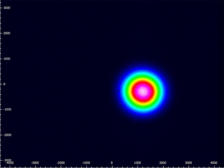
Full Transmission
Click to Enlarge
Figure 4.2 Beam profile after traveling through a OM6 modulator with full transmission.
20% Transmission
Click to Enlarge
Figure 4.3 Beam profile after traveling through a OM6 modulator with 20% transmission.
10% Transmission
Click to Enlarge
Figure 4.4 Beam profile after traveling through a OM6 modulator with 10% transmission.
| Fast Laser Power Modulator Side Panel | |
|---|---|
| Callout | Description |
| 1 | 0 to 1 V Modulation Voltage (BNC) |
| 2 | DC Power Switch |
| 3 | LED Power Indicator |
| 4 | DC Power Cord Connector for Modulator (R7B) |
| 5 | DC Power Cord Connector for Photodetector |
| 6 | 0 to 10 V Photodetector Output (BNC) |
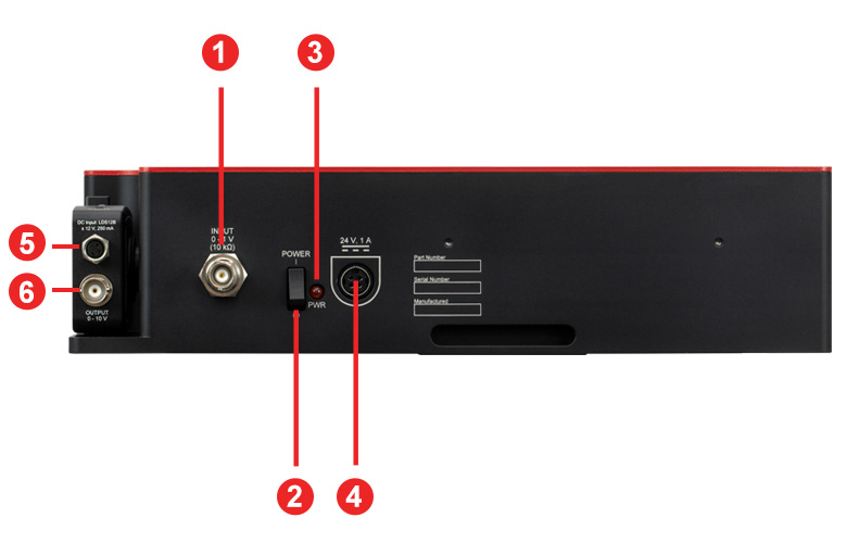
Click to Enlarge
Figure 5.1 High-Speed Optical Modulator Electrical Connections
OM6 Series Fast Laser Power Modulator Connections
BNC Female, Modulation Signal Input
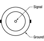
Modulation Signal Input is 0 - 1 V
KPJX-4S-S Connector, Female Power IN

PDA100A2 & PDA20CS2 Photodetector Connections
BNC Female Output (Photodetector)
0 - 10 V Output
Male (Power Cable)*
*For the Included LDS12B Power Supply
Female Power IN (Photodetector)

| Posted Comments: | |
Yaqing Zhang
(posted 2021-07-03 03:41:25.42) Hi,
Could you please provide the optical path length from the input aperture to output aperture of the fast modulator (OM6NH)? The specs says the internal optical path length is 100mm, but the housing length is already 290.83 mm, so I believe the optical path from the two apertures must be larger than 290.83mm.
Thanks! YLohia
(posted 2021-07-12 10:36:04.0) Hello, thank you for bringing this typo to our attention. The path length is approximately 100 cm, not 100 mm. This will be corrected on our web documentation shortly. |