 Products Home / Optomechanical Components / Optomechanical Mounts / Component Mounts / XY Translation Adapter for Fixed Optic Mounts
XY Translation Adapter for Fixed Optic Mounts

- Provides XY Travel Over a 50 mm x 30 mm Area
- 8-32 (M4) Taps and #8 (M4) Counterbores for Attaching Fixed Optic Mounts and Other Small Components
- 8-32 (M4) Tapped Holes for Mounting Vertically or Horizontally to an Optical Post
XYA1
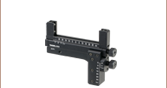
XY Translation Adapter
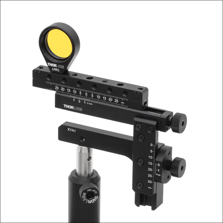
Application Idea
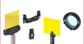
The XYA1 Translation Adapter with a Mounted LMR1 Lens Mount and Dichroic Beamsplitter


Please Wait
Click to Enlarge
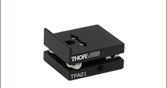
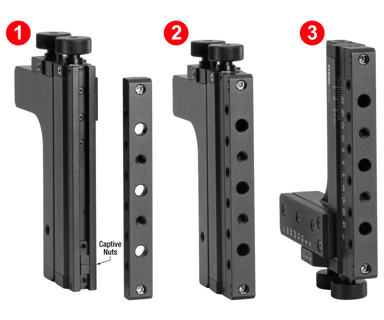
In order to secure an optic mount using the counterbores, the top bar needs to be removed. To reattach it, (1) tilt one end of the XYA1(/M) translation adapter downwards and allow both 2-56 captive nuts to slide to the bottom of the channel. (2) Align and tighten the bottom screw in the top bar. (3) Flip the translation adapter to allow the second 2-56 captive nut to slide to the bottom. Note that the nut will not be visible as it will be behind the partially attached top bar. The second screw can then be tightened and the top bar secured.
Features
- XY Translation Over a 50 mm (1.97") x 30 mm (1.18") Area
- Removable Top Bar for Mounting Fixed Optic Mounts and Other Small Components
- Two 8-32 (M4 x 0.7) Tapped and Three #8 (M4) Counterbores in the Top Surface
- Six 8-32 (M4 x 0.7) Tapped Through Holes on the Sides
- Supports Added Component Weight of <0.20 kg
- Each Axis Includes a Vernier Scale that Provides 100 µm Resolution
- Lockable Translation Axes for Repeatable Positioning
- Five 8-32 (M4) Tapped Holes for Mounting to Ø1/2" Posts
Thorlabs' XYA1(/M) Two-Axis Translation Adapter provides XY translation for fixed optic mounts (such as fixed lens, fixed mirror, and fixed filter mounts) and other small components that attach via an 8-32 (M4) tap or counterbore. The removable top bar features two 8-32 (M4 x 0.7) tapped holes and three #8 (M4) counterbored holes on the top, with six 8-32 (M4 x 0.7) tapped through holes on the sides. These features make the adapter ideal for general applications as well as home-built microscopy systems. For a version of this XY translation adapter that directly accepts rectangular optics, please see the XYF1(/M) Rectangular Optic Mount.
Two actuator knobs on the side of the mount enable manual positioning over a 50 mm (1.97") x 30 mm (1.18") area, which can be oriented either vertically or horizontally. These actuators can be adjusted by hand or with a 5/64" (2 mm) hex key or ball driver (not included). Next to each knob is a brass setscrew with a 5/64" (2 mm) hex for locking the traslation axes, allowing for lockable, repeatable positioning of the mounted component. This mount is also equipped with a vernier scale that provides a resolution of 100 µm; please see the Vernier Scales tab for more information. Five 8-32 (M4) tapped holes support several possible mounting orientations when used with our Ø1/2" posts, such that either translation axis can be oriented vertically or both axes can be oriented horizontally. A selection of possible mounting orientations is shown below.
The removable top bar is secured via two captive 5/64" (2 mm) hex setscrews which lock it in place. By loosening these locking screws, the top bar can be removed so that components can be mounted using the counterbored holes. To reattach the top bar, tip the adapter towards one end so that the 2-56 captive nuts in the top channel fall to one side. Replace the top bar and tighten the lower of the captive 5/64" (2 mm) hex setscrews. Then, tilt the adapter towards the other end and allow the second 2-56 captive nut to slide to that side of the adapter. The second locking screw can then be tightened, securing the top bar in place. This process can be seen in the images to the right.

Click to Enlarge
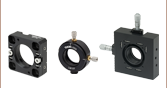
The XYA1 Adapter has five 8-32 (M4) taps, allowing for several post-mountable orientations (see images to the right for examples).

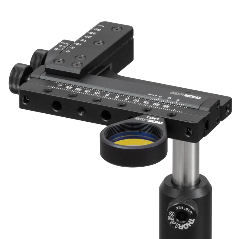
The XYA1 Adapter can be used in conjunction with fixed filter and lens mounts to position test targets, dichroic beamsplitters, and other optics. Either translation axis can be oriented vertically, or they can both be oriented horizontally.
Reading a Vernier Scale on a Linear Main Scale
Vernier scales are typically used to add precision to standard, evenly divided scales (such as the scales on Thorlabs' rotation, goniometric, or translation mounts). A vernier scale has found common use in many precision measurement instruments, the most common being calipers and micrometers. The vernier scale uses two scales side-by-side: the main scale and the vernier scale. The direct vernier scale has a slightly smaller spacing between its tick marks owing to the vernier scale having N ticks for every N - 1 ticks on the main scale. Hence, the lines on the main scale will not line up with all the lines on the vernier scale. Only one line from the vernier scale will match well with one line of the main scale, and that is the trick to reading a vernier scale.
Figures 130A through 130C show a linear vernier scale system for three different situations. In each case, the scale on the left is the main scale, while the small scale on the right is the vernier scale. When reading a vernier scale, the main scale is used for the gross number, and the vernier scale gives the precision value. In this manner, a standard ruler or micrometer can become a precision instrument.
The 0 on the vernier scale is the "pointer" (marked by a red arrow in Figures 130A through 130E) and will indicate the main scale reading. In Figure 130A we see the pointer is lined up directly with the 75.6 line. Notice that the only other vernier scale tick mark that lines up well with the main scale is 10. Since the pointer lines up with the main scale’s 75.6, the reading from Figure 130A is 75.60 (in whatever units the instrument measures).
That is essentially all there is to reading a vernier scale. It's a very straightforward way of increasing the precision of a measurement instrument. To expound, let’s look at Figure 130B. Here we see that the pointer is no longer aligned with a line on the main scale, but instead it is slightly above 75.6 and below 75.7; thus, the gross measurement is 75.6. The first vernier line that coincides with a main scale line is the 5, shown with a blue arrow. The vernier scale gives the final digit of precision; since the 5 is aligned to the main scale, the precision measurement for Figure 130B is 75.65.
Since this vernier scale is 10% smaller than the main scale, moving the vernier scale by 1/10 of the main scale will align the next vernier marking. This asks the obvious question: what if the measurement is within the 1/10 precision of the vernier scale? Figure 130C shows just this. Again, the pointer line is in between 75.6 and 75.7, yielding the gross measurement of 75.6. If we look closely, we see that the vernier scale 7 (marked with a blue arrow) is very closely aligned to the main scale, giving a precision measurement of 75.67. However, the vernier scale 7 is very slightly above the main scale mark, and we can see that the vernier scale 8 (directly above 7) is slightly below its corresponding main scale mark. Hence, the scale on Figure 130C could be read as 75.673 ± 0.002. A reading error of about 0.002 would be appropriate for
this instrument.
Click to Enlarge
Figure 130A An example of how to read a vernier scale. The red arrow indicates what is known as the pointer. Since the tick mark labeled 10 on the vernier scale aligns with one of the tick marks on the main scale, this vernier scale is reading 75.60 (in whatever units the instrument measures).

Click to Enlarge
Figure 130B The red arrow indicates the pointer and the blue arrow indicates the vernier line that matches the main scale. This scale reads 75.65.
Click to Enlarge
Figure 130C The red arrow indicates the pointer, and the blue arrow indicates the vernier line that matches the main scale. This scale reads 75.67 but can be accurately read as
75.673 ± 0.002.
Reading a Vernier Scale on a Rotating Main Scale
The vernier scale may also be used on rotating scales where the main scale and vernier scale do not share units. Figures 130D and 130F show a vernier scale system for two different situations where the main scale is given in degrees and the vernier scale has ticks every 5 arcmin (60 arcmin = 1°). In each case, the scale on the top is the main scale, while the small scale on the bottom is the vernier scale.
In Figure 130D we see the pointer is lined up directly with the 341° line. Notice that the only other vernier scale tick marks that line up well with the main scale are ±60 arcmin. Since the pointer lines up with the main scale at 341°, the reading from Figure 130D is 341.00°.
There are two ways to determine the reading if the zero on the vernier scale line is between two lines of the main scale. For the first method, take the line on the left side of the pointer on the vernier scale and subtract that value (in arcmin) from the value on the main scale that is to the right on the main scale. As an example, in Figure 130E the vernier pointer is between 342° and 343°; using the left blue arrow of the vernier scale results in
As we've seen here, vernier scales add precision to a standard scale measurement. While it takes a bit of getting used to, with a little practice, reading these scales is fairly straightforward. Vernier scales, whether they are direct or retrograde*, are read in the same fashion.
*A retrograde vernier scale has a larger spacing between its tick marks with N ticks for every N + 1 ticks on the main scale.
Click to Enlarge
Figure 130D An example of a vernier scale where the main scale and the vernier scale are in different units (degrees and arcmins, respectively). The red arrow indicates the pointer. This scale reads 341.00°.
Click to Enlarge
Figure 130E The red arrow indicates the pointer and the blue arrows give the precision value from the vernier scale.
This scale reads 342.75°.
| Posted Comments: | |
Tomas Peciva
(posted 2023-09-25 14:36:35.907) Hi ThorLabs team, is it possible to re-save the stage XYA1/M as an assembly and save it in older version of solidworks 2020. I have trouble with import of latest version.
Thank you
Tomas jdelia
(posted 2023-09-26 10:51:53.0) Thank you for contacting Thorlabs. While we do not provide older version SolidWorks files for this adapter, you can download the Step file directly here: https://www.thorlabs.com/_sd.cfm?fileName=TTN278829-E0W.step&partNumber=XYA1/M. |