 Products Home
Thermal Power Sensors (C-Series)
- Power Ranges Covering 10 µW to 200 W
- Wavelength Ranges Covering 190 nm to 20 µm
- Broadband Coatings with High Damage Thresholds
- Sensors Designed for Microscopes and Pulsed Lasers
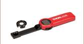
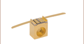
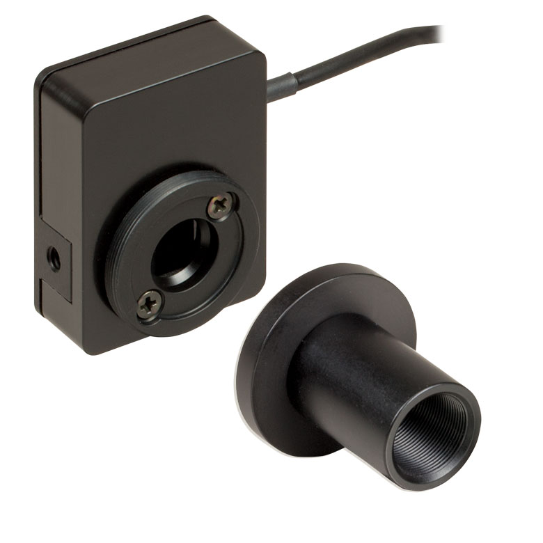
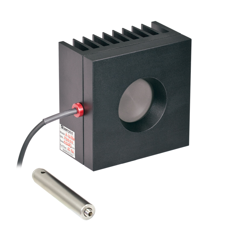
S425C-L
Featuring Removable
Heat Sink and Shown
with a Fiber Adapter
(Sold Below) and
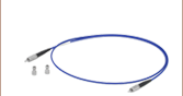
Fiber Patch Cable
S350C
For Excimer Lasers
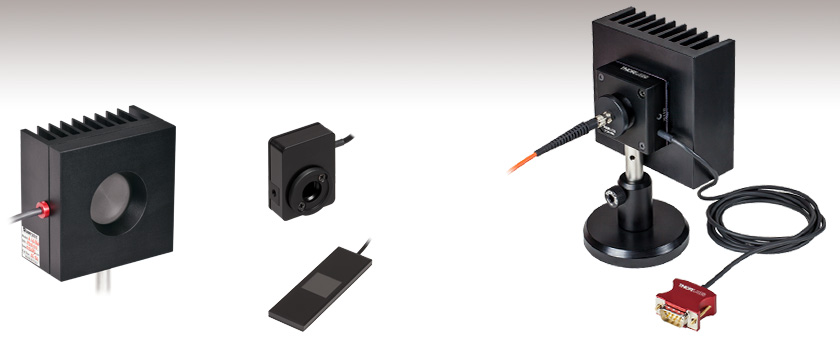
S401C
High Sensitivity
Down to 10 µW
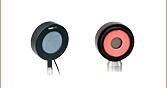
S175C
18 mm x 18 mm Aperture Size
for Use with Microscopes


Please Wait
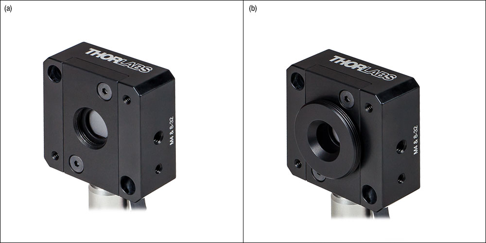
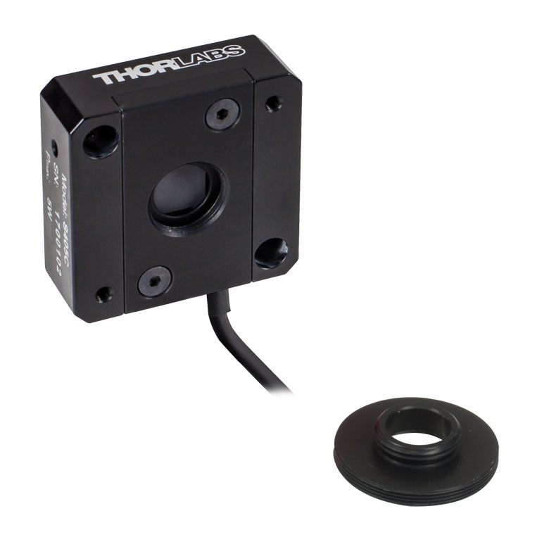
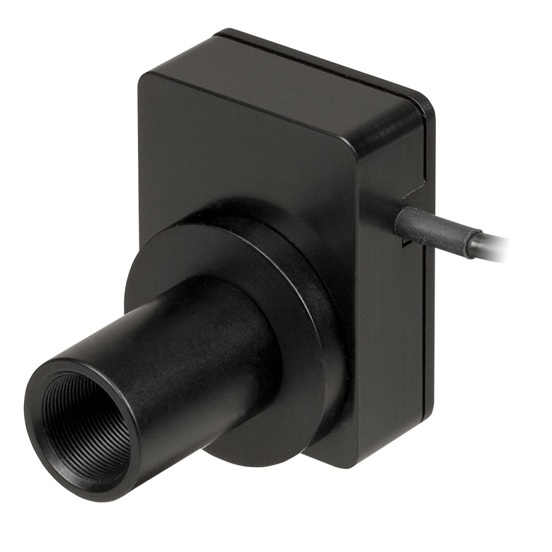
Figure 1.2 Internal SM05 (0.535"-40) threading on the S405C's aperture as shown in (a) accepts the included external SM05 to SM1 (1.035"-40) thread adapter as shown in (b). Most sensors include an SM1 externally threaded adapter that allows accessories like fiber adapters to be mounted.
Click to Enlarge
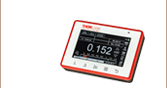
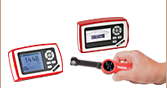
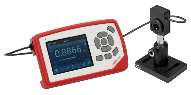
Figure 1.1 S401C Connected to the PM100D2 Console
| Power Meter Selection Guide |
|---|
| Sensors |
| Photodiode Power Sensors |
| Thermal Power Sensors |
| Thermal Position & Power Sensors |
| Pyroelectric Energy Sensors |
| Power Meter Consoles and Interfaces |
| Digital Handheld Consoles |
| Analog Handheld Console |
| Touchscreen Handheld Console |
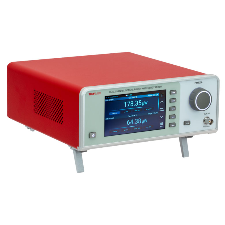
| Dual-Channel Benchtop Console |
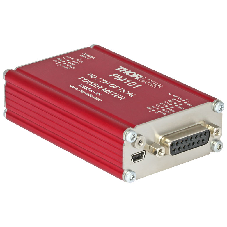
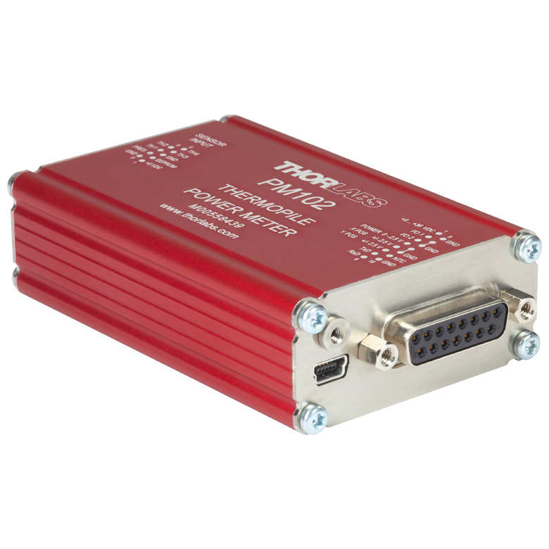
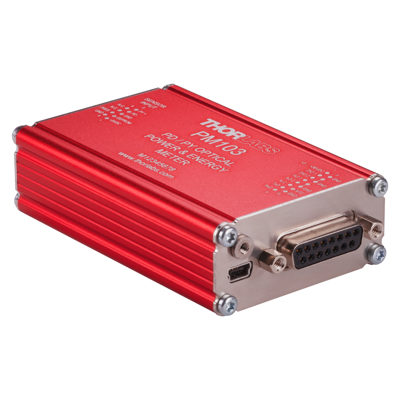
| USB Interfaces with External Readout |
| Complete Power Meters |
| Power Meter Bundles |
| Wireless Power Meters with Sensors |
| Compact USB Power Meters |
| Field Power Meters for Terminated Fibers |
Features
- Broad Spectral Ranges with Relatively Flat Spectral Responses (See Figures G1.2, G2.1, G3.1, G4.1, and G5.3)
- Individually Calibrated with NIST- and PTB-Traceable Certificate of Calibration
- Free-Space and Fiber-Based Applications Supported
- All Sensors Accept Free Space Input
- Majority Accept Fiber Adapter (Available Below) for Fiber-Based Input
- C-Series Connector
- Enables Quick Sensor Connection to Our Power Meter Consoles
- Embedded EEPROM Contains Sensor and Calibration Data
- Ten Models Feature Over-Temperature-Alert Sensor (See Specs Tab for Details)
Thorlabs' C-Series Thermal Power Sensors are collectively able to detect power ranges from 10 µW to 200 W and wavelength ranges from 190 nm to 20 µm. These thermopile-based sensors are ideal choices for measuring broadband spectra from amplified spontaneous emission (ASE) sources, light emitting diodes (LEDs), filament lamps, swept-wavelength lasers, and other sources. In addition, thermal power sensors do not saturate, which makes them well suited to measuring pulsed sources with high pulse peak powers or long-duration pulses. These thermal power sensors also exhibit low dependency on the angle and position of the incident light beam. They are preferred for applications that cannot tolerate the strong wavelength dependencies and/or saturation thresholds of photodiode sensors. However, thermal power sensors generally have lower power resolutions and longer response times. We offer a wide range of thermal power sensors, with each including different design features.
Mounting
The sensors sold here (except the S175C) can be mounted on our Ø1/2" Posts using an 8-32, M4, or M6 tap. A 60 mm or 75 mm tall post is included with select sensors. Additionally, many of our thermal sensors are compatible with 30 mm cage systems, Ø1" lens tube systems, and our fiber adapters (sold below). Please refer to the Specs tab for more information.
Calibration
Each sensor head is individually calibrated and is shipped with a NIST- and PTB-Traceable Calibration Certificate. The calibration and identification data is stored in the electrically erasable programmable read-only memory (EEPROM) built into the connector of the sensor and is downloaded automatically to the connected power meter console. The EEPROM also contains sensor model and serial numbers, wavelength range, information on the built-in thermistor (when present), and the calibration date. For more information on sensor calibration, please see the Calibration tab on our Power Meter and Sensor Tutorial.
Power Meter Compatibility
All sensors are connected to the power meter console via the C-Series connector, which offers quick sensor exchange. These sensors are compatible with our current power meter console offering but cannot be used with our previous generation of consoles. For our sensors with natural response times greater than 1 second, these power meters can use the data stored in the connector to predict the incident power after a single time constant of the sensor. Please see the Operation tab for more information.
Recalibration Services
Thorlabs offers manufacturer recalibration services for our thermal power sensors. To ensure accurate measurements, we recommend recalibrating these sensors annually. This service can be ordered below (see Item #
Sensor Upgrade and Service
All C-Series Sensors are incompatible with former generation power meter consoles with non-C-Series connectors. We offer a sensor upgrade service if you want to use your existing sensors with a new power meter console with a C-Series connector. Note: upgraded sensors will be incompatible with old power meter consoles with non-C-Series connectors. Please contact our Tech Support team for details.
| Thermal Power Sensors Quick Links | |||||
|---|---|---|---|---|---|
| Type | High Resolution | Max Power: 10 W | Max Power: 40 W to 200 W | High Max Power Density for Pulsed Lasers |
Microscope Slide Thermal Sensor |
| Wavelength Rangea | 190 nm - 20 µm | 190 nm - 20 µm | 190 nm - 20 µm | 250 nm - 10.6 µm | 300 nm - 10.6 µm |
| Optical Power Rangea | 10 µW - 5 W | 2 mW - 10 W | 10 mW - 200 W | 100 µW - 10 W | 100 µW - 2 W |
| Max Optical Power Densitya | 500 W/cm² - 1500 W/cm² (Avg.) | 1500 W/cm² (Avg.) | 2 kW/cm² - 4 kW/cm² (Avg.) | 35 W/cm² (Avg.); 100 GW/cm² (Peak, 1 ns Pulse) |
200 W/cm² |
| Resolutiona | 1 µW - 5 µW | 100 µW | 100 µW - 5 mW | 10 µW - 250 µW | 10 µW |
Thorlabs' Thermal Power Sensors (C-Series)
Click on the links in the following list or Selection Guide to move to the indicated specification tables.
- High Resolution
- Max Power: 10 W
- Max Power: 40 W to 200 W
- High Max Power Density for Pulsed Lasers
- Microscope Slide Thermal Sensor
For details on sensor-related terminology, see our list of definitions.
High Resolution
| Item # | S401C | S405C |
|---|---|---|
| Detection Specifications | ||
| Detector Type | Thermal Surface Absorber with Background Compensation (Axial Thermopile) |
Thermal Surface Absorber (Axial Thermopile) |
| Wavelength Range | 190 nm - 20 µm | 190 nm - 20 µm |
| Optical Power Range | 10 µW - 1 W | 100 µW - 5 W |
| Max Average Power Densitya | 500 W/cm² | 1.5 kW/cm² |
| Max Pulse Energy Density | 0.2 J/cm² (1 µs Pulse), 2 J/cm² (1 ms Pulse) |
0.3 J/cm² (1 ns Pulse), 5 J/cm² (1 ms Pulse) |
| Max Intermittent Powerb | 3 W | - |
| Linearity | ±0.5% | ±0.5% |
| Resolutionc | 1 µW | 5 µW |
| Measurement Uncertaintyd (Calibration Uncertainty) |
±3% @ 1064 nm ±5% @ 190 nm - 10.6 µm |
±3% @ 1064 nm ±5% @ 250 nm - 17 µm |
| Response Timee | 1.1 s | 1.1 s |
| General Information | ||
| Suggested Application | Low-Power Lasers and LEDs | Low-Power Lasers and LEDs |
| Absorber | High-Power Broadband Coating | High-Power Broadband Coating |
| Cooling | Convection (Passive) | |
| Temperature Sensor (In Sensor Head) | NTC Thermistor | NTC Thermistor |
| Compatible Consoles | PM100A, PM100D2, PM100D3, PM400, and PM5020 | |
| Compatible Interfaces | PM101, PM101A, PM101R, PM101U, PM102, PM102A, PM102U, and PM100USB | |
| Mechanical Specs | ||
| Housing Dimensions (Without Adapter) |
33.0 m x 43.0 mm x 15.0 mm (1.30" x 1.69" x 0.59") |
40.6 mm x 40.6 mm x 16.0 mm (1.60" x 1.60" x 0.63") |
| Sensor Input Aperture | Ø10 mm | Ø10 mm |
| Active Detector Area | 10 mm x 10 mm | 10 mm x 10 mm |
| Distance to Detectorf | 3 mm | 5 mm |
| Cable Length | 1.5 m | |
| Connector | D-Sub 9 Pin Male | |
| Weight | 0.05 kg (0.11 lb) | 0.11 kg (0.24 lb) |
| Mounting and Accessories | ||
| Post | Ø1/2" Post via Universal 8-32 & M4 Tap (Post Not Included) |
Ø1/2" Post via Universal 8-32 & M4 Tap (Post Not Included) |
| Cage System Mounting | N/A | 30 mm Cage Systems via Two 4-40 Tapped Holes; Two Ø6 mm Through Holes for ER Series Rods |
| Aperture Thread | Internal SM05 | Internal SM05 |
| Accessories | Internally SM1-Threaded Adapter with an Internally SM05-Threaded Light Shield |
Adapter with External SM05 and External SM1 Threads |
| Fiber Adapters (Available Below) | S120 Series Fiber Adapters | |
Max Power: 10 W
| Item # | S415C | S425C |
|---|---|---|
| Detection Specifications | ||
| Detector Type | Thermal Surface Absorber (Axial Thermopile) |
Thermal Surface Absorber (Axial Thermopile) |
| Wavelength Range | 190 nm - 20 µm | 190 nm - 20 µm |
| Optical Power Range | 2 mW - 10 W | 2 mW - 10 W |
| Max Average Power Densitya | 1.5 kW/cm² | 1.5 kW/cm² |
| Max Pulse Energy Density | 0.3 J/cm² (1 ns Pulse), 5 J/cm² (1 ms Pulse) |
0.3 J/cm² (1 ns Pulse), 5 J/cm² (1 ms Pulse) |
| Max Intermittent Powerb | 20 W | 20 W |
| Linearity | ±0.5% | ±0.5% |
| Resolutionc | 100 µW | 100 µW |
| Measurement Uncertaintyd (Calibration Uncertainty) |
±3% @ 1064 nm ±5% @ 250 nm - 17 µm |
±3% @ 1064 nm ±5% @ 250 nm - 17 µm |
| Response Timee | 0.6 s | 0.6 s |
| General Information | ||
| Suggested Application | Low and Mid-Power Lasers & LEDs | Low and Mid-Power Lasers & LEDs |
| Absorber | High-Power Broadband Coating | High-Power Broadband Coating |
| Cooling | Convection (Passive) | |
| Temperature Sensor (In Sensor Head) |
NTC Thermistor | |
| Compatible Consoles | PM100A, PM100D2, PM100D3, PM400, and PM5020 | |
| Compatible Interfaces | PM101, PM101A, PM101R, PM101U, PM102, PM102A, PM102U, and PM100USB | |
| Mechanical Specs | ||
| Housing Dimensions (Without Adapter) |
50.8 mm x 50.8 mm x 35.0 mm (2.00" x 2.00" x 1.38") |
50.8 mm x 50.8 mm x 35.0 mm (2.00" x 2.00" x 1.38") |
| Sensor Input Aperture | Ø15 mm | Ø25.4 mm |
| Active Detector Area | Ø15 mm | Ø27 mm |
| Distance to Detectorf | 5 mm | 4.6 mm |
| Cable Length | 1.5 m | |
| Connector | D-Sub 9-Pin Male | |
| Weight | 0.22 kg (0.49 lb) | 0.22 kg (0.49 lb) |
| Mounting and Accessories | ||
| Post | Ø1/2" Post via Universal 8-32 & M4 Tap (Post Not Included) | Ø1/2" Post via Universal 8-32 & M4 Tap (Post Not Included) |
| Cage System Mounting | N/A | N/A |
| Aperture Thread | Internally SM1-Threaded Aperture External SM1-Threaded Adapter for Ø1" Lens Tubes and Fiber Adapters |
Internally SM1-Threaded (1.035"-40) with External SM1-Threaded Adapter for Ø1" Lens Tubes and Fiber Adapters |
| Fiber Adapters (Available Below) | S120 Series Fiber Adapters | |
Max Power: 40 W to 200 W
| Item # | S350C | S425C-L | S322C |
|---|---|---|---|
| Detection Specifications | |||
| Detector Type | Thermal Surface Absorber (Radial Thermopile) |
Thermal Surface Absorber (Axial Thermopile) |
Thermal Surface Absorber (Radial Thermopile) |
| Wavelength Range | 190 nm - 1.1 µm, 10.6 µm | 190 nm - 20 µm | 250 nm - 11 µm |
| Optical Power Range | 10 mW - 40 W | 2 mW - 50 W | 100 mW - 200 W |
| Max Average Power Densitya | 2 kW/cm² | 1.5 kW/cm² | 4 kW/cm² |
| Max Pulse Energy Density | 0.7 J/cm² (1 ns Pulse), 10 J/cm² (1 ms Pulse) |
0.3 J/cm² (1 ns Pulse), 5 J/cm² (1 ms Pulse) |
0.5 J/cm² (1 ns Pulse), 10 J/cm² (1 ms Pulse) |
| Max Intermittent Powerb (2 Minute Max) |
60 W | 75 W | 250 W |
| Linearity | ±1% | ±0.5% | ±1% |
| Resolutionc | 1 mW | 100 µW | 5 mW |
| Measurement Uncertaintyd (Calibration Uncertainty) |
±3% @ 1064 nm ±5% @ 190 nm - 1100 nm, 10.6 µm |
±3% @ 1064 nm ±5% @ 250 nm - 17 µm |
±3% @ 1064 nm ±5% @ 266 nm - 1064 nm |
| Response Timee | 9 s (1 s from 0 to 90%) |
0.6 s | 5 s (1 s from 0 to 90%) |
| General Information | |||
| Suggested Application | High-Power Excimer Lasers | Mid-Power Lasers | Mid-Power Lasers |
| Absorber | Excimer Coating | High-Power Broadband Coating | High-Power Broadband Coating |
| Cooling | Convection (Passive) | Forced Air with Fanef | |
| Temperature Sensor (In Sensor Head) |
NTC Thermistor | ||
| Compatible Consoles | PM100A, PM100D2, PM100D3, PM400, and PM5020 | ||
| Compatible Interfaces | PM101, PM101A, PM101R, PM101U, PM102, PM102A, PM102U, and PM100USB | ||
| Mechanical Specs | |||
| Housing Dimensions (Without Adapter, if Applicable) |
100 mm x 100 mm x 54.2 mm (3.94" x 3.94" x 2.13") |
100.0 mm x 100.0 mm x 58.0 mm (3.94" x 3.94" x 2.28") |
100 mm x 100 mm x 86.7 mm (3.94" x 3.94" x 3.41") |
| Sensor Input Aperture | Ø40 mm | Ø25.4 mm | Ø25 mm |
| Active Detector Area | Ø40 mm | Ø27 mm | Ø25 mm |
| Distance to Detectorg | 13 mm | 4.6 mm | 15 mm |
| Cable Length | 1.5 m | ||
| Connector | D-Sub 9-Pin Male | ||
| Weight | 1 kg (2.20 lb) | 0.71 kg (1.57 lb) | 0.75 kg (1.65 lb) |
| Mounting and Accessories | |||
| Post | M6, 75 mm Long Ø1/2" Post Included | Ø1/2" Post via Universal 8-32 & M4 Tap (Post Not Included) | M6, 75 mm Long Ø1/2" Post Included |
| Cage System Mounting | N/A | N/A | 30 mm Cage Systems via Four 4-40 Tapped Holes |
| Aperture Thread | Unthreaded | Internally SM1-Threaded Aperture with External SM1-Threaded Adapter for Ø1" Lens Tubes and Fiber Adapters |
Externally SM1-Threaded Adapter for Ø1" Lens Tubes and Fiber Adapters |
| Fiber Adapters (Available Below) | S120 Series Fiber Adapters | ||
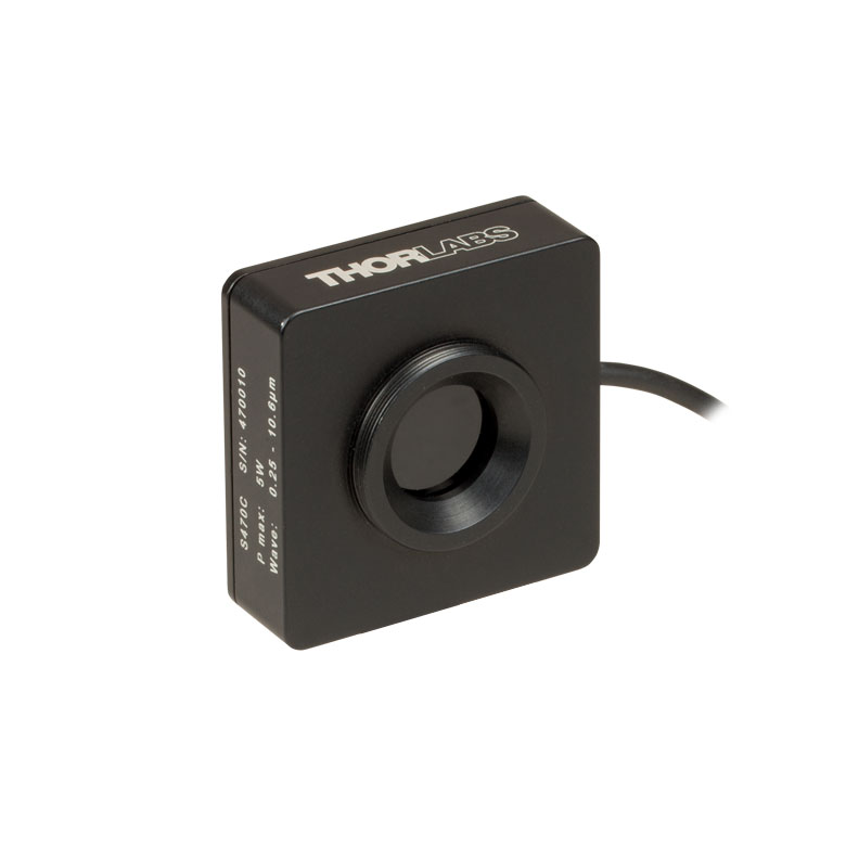
High Max Power Density for Pulsed Lasers
| Item # | S370C | S470C |
|---|---|---|
| Detection Specifications | ||
| Detector Type | Thermal Volume Absorber (Axial Thermopile) |
Thermal Volume Absorber (Axial Thermopile) |
| Wavelength Range | 0.4 µm - 5.2 µm | 0.25 µm - 10.6 µm |
| Optical Power Range | 10 mW - 10 W | 100 µW - 5 W |
| Max Power Density | 35 W/cm² (Avg); 100 GW/cm² (Peak, 1 ns Pulse) |
35 W/cm² (Avg); 100 GW/cm² (Peak, 1 ns Pulse) |
| Max Pulse Energy Density | 1 J/cm² (1 ns pulse) 10 J/cm² (1 ms pulse) |
1 J/cm² (1 ns Pulse) |
| Max Intermittent Powera | 15 W | - |
| Linearity | ±1% | ±0.5% |
| Resolutionb | 250 µW | 10 µW |
| Measurement Uncertaintyc (Calibration Uncertainty) |
±3% @ 1064 nm ±5% @ 400 nm - 1064 nm |
±3% @ 1064 nm ±5% @ 250 nm - 10.6 µm |
| Response Timed | 45 s (3 s from 0 to 90%) |
6.5 s (<2 s from 0 to 90%) |
| General Information | ||
| Suggested Application | High Peak Power Lasers | High Peak Power, Low Average Power Lasers |
| Absorber | Broadband Volume Absorber (Schott NG1 Filter) |
Broadband Volume Absorber (Schott NG1 Filter) |
| Cooling | Convection | Convection |
| Temperature Sensor (In Sensor Head) |
N/A | N/A |
| Compatible Consoles | PM100A, PM100D2, PM100D3, PM400, and PM5020 | |
| Compatible Interfaces | PM101, PM101A, PM101R, PM101U, PM102, PM102A, PM102U, and PM100USB | |
| Mechanical Specs | ||
| Housing Dimensions (Without Adapter, if Applicable) |
75 mm x 75 mm x 51.2 mm (2.95" x 2.95" x 2.02") |
45.0 mm x 45.0 mm x 18.0 mm (1.77" x 1.77" x 0.71") |
| Input Aperture Size | Ø25 mm | Ø15 mm |
| Active Detector Areae | Ø25 mm | >Ø15 mm |
| Distance to Detectorf | 13 mm | 5.1 mm |
| Cable Length | 1.5 m | 1.5 m |
| Connector | Sub-D 9-Pin Male | Sub-D 9-Pin Male |
| Weight | 0.5 kg (1.10 lb) | 0.1 kg (0.22 lb) |
| Mounting and Accessories | ||
| Post | M6, 75 mm Long Post Included | Universal 8-32 / M4 Tap, Post Not Included |
| Cage System Mounting | 4 x 4-40 Threads for 30 mm Cage Compatibility |
N/A |
| Aperture Thread | Externally SM1-Threaded Adapter for Ø1" Lens Tubes and Fiber Adapters |
External SM1-Threaded Aperture for Ø1" Lens Tubes and Fiber Adapters |
| Fiber Adapters (Available Below) | S120 Series Fiber Adapters | S120 Series Fiber Adapters |
Microscope Slide Thermal Sensor
| Item # | S175C |
|---|---|
| Detection Specifications | |
| Detector Type | Thermal Absorber (Axial Thermopile) |
| Wavelength Range | 0.3 µm - 10.6 µm |
| Optical Power Range | 100 µW - 2 W |
| Max Power Density | 200 W/cm2 |
| Max Pulse Energy Density | 0.1 J/cm² (1 µs pulse) 1 J/cm² (1 ms pulse) |
| Max Intermittent Power | - |
| Linearity | ±0.5% |
| Resolutiona | 10 µW |
| Measurement Uncertaintyb (Calibration Uncertainty) |
±3% @ 1064 nm ±5% @ 300 nm - 10.6 µm |
| Response Timec | 3 s (<2 s from 0 to 90%) |
| General Information | |
| Suggested Application | Light Measurement on the Microscope Objective Plane |
| Absorber | Broadband Coating |
| Cooling | Convection |
| Temperature Sensor (In Sensor Head) |
N/A |
| Compatible Consoles | PM100A, PM100D2, PM100D3, PM400, and PM5020 |
| Compatible Interfaces | PM101, PM101A, PM101R, PM101U, PM102, PM102A, PM102U, and PM100USB |
| Mechanical Specs | |
| Housing Dimensions | 76 mm x 25.2 mm x 4.8 mm (2.99" x 0.99" x 0.19") |
| Input Aperture Size | 18 mm x 18 mm |
| Active Detector Area | 18 mm x 18 mm |
| Distance to Detectord | 1.1 mm |
| Cable Length | 1.5 m |
| Connector | Sub-D 9-Pin Male |
| Weight | 0.05 kg (0.11 lb) |
| Mounting and Accessories | |
| Post | N/A |
| Cage System Mounting | N/A |
| Aperture Thread | N/A |
| Fiber Adapters (Available Below) | N/A |
C-Series Sensor Connector
D-Type Male
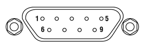
| Pin | Connection |
|---|---|
| 1 | Not Used |
| 2 | EEPROM Data |
| 3 | Sensor and NTC Ground |
| 4 | Not Used |
| 5 | Not Used |
| 6 | EEPROM Ground |
| 7 | NTC |
| 8 | Sensor Signal |
| 9 | Not Used |
Operational Principle
Click to Enlarge
Figure 4.1 A thermal sensor with radially configured thermocouples, which is depicted as seen from the top. Light is incident on the absorbing layer at the center, and heat flows through the thermocouples to the heat sink.

Click to Enlarge
Figure 4.2 A thermal sensor with axially configured thermocouples, which is depicted as seen from the side. Light is incident on the top, and heat flows down through the thermocouple layer and dissipates in the heat sink below.
Thorlabs' Thermal Power Sensors are based on thermopiles. The top layer of the sensor consists of a light-absorbing material. A region filled with multiple thermocouples, which are connected in series, is immediately adjacent to the absorber. Thermocouples are made by bringing two dissimilar metals into contact, and their point of contact is called a junction. On the other side of the thermocouples is a heat sink. The thermocouples are connected in series, and the placement of the junctions alternates from being in close proximity to the absorber to being in close proximity to the heat sink.
The absorber converts incident light energy into heat. The heat flows from the absorber, across the thermocouples, and to the heat sink, where it dissipates. The temperatures of the thermocouple junctions placed close to the absorber are higher than those the adjacent junctions placed close to the heat sink. This arrangement takes advantage of the thermoelectric (Seebeck) effect, in which a temperature difference between the adjacent junctions generates a proportional voltage difference. By connecting multiple thermocouples in series, the magnitude of the generated voltage is increased. The thermocouples are often arranged in a radial (also called a disk) configuration, as illustrated in Figure 4.1, or in an axial (also called a matrix) configuration, which is diagrammed in Figure 4.2. Thermal power sensors with both types of configurations are available from Thorlabs.
Radial Configuration of Thermocouples
A diagram of a thermal power sensor with a radial thermopile is shown in Figure 4.1, viewed from the top. This construction places the light absorber at the center. It is surrounded by a concentric ring of thermocouples connected in series, which are surrounded by a concentric heat sink. Light incident on the absorber generates heat that flows in a radial direction through the thermocouples and towards the heat sink. The heat sink must be specially designed so that it is in good mechanical contact with the outer ring of thermocouple junctions, without being in thermal contact with the light absorber or the inner ring of thermocouple junctions. The area behind the absorber cannot be in thermal contact with anything that will divert the heat flow from its intended radial path of flow.
A benefit of the radial construction is that sensors can be designed to measure power levels as high as kilowatts. This high upper limit is made possible both by the thickness of the sensor disk and by displacing the thermocouples from the absorber, which protects them from the conditions in the laser impact area. Disadvantages of the radial thermopiles include the use of a heat sink with a special design, which adds complexity when customizing the sensor head, and a sensor head which is generally a least twice the diameter of the active detector area. Resolution for radial thermal power sensors is typically limited to around 10 mW.
Thorlabs' thermal power sensors featuring a radial configuration include the S350C and S322C, which are all designed for mid-power range applications.
Axial Configuration of Thermocouples
A diagram of a thermal power sensor with an axial configuration of thermocouples is shown in Figure 4.2. In this design, the thermocouples are arranged between two flat layers. One layer is the light absorber, and the other is the heat sink. As the heat flows directly from the front surface to the back side, the dimensions of these sensor packages can be made compact. The sensor housing can be approximately the same size as the active detector area.
The new generation of axially-designed sensors achieves high resolutions in the microwatt range while providing relatively fast response times. These sensors detect optical powers up to several Watts, which limited mostly by the thickness of the absorbing material. The performance of the newly designed sensors, which includes the S401C and S405C, contrasts with sensors of previous generations, which have slower response times.
Heat sink shapes and dimensions are much less constrained for axially, as compared with radially, configured thermopiles. Heat sinks for axial designs can be as simple as a block of aluminum attached with thermal glue, or as sophisticated as a metal-core PCB that is soldered to the sensor. Our S415C, S425C, and S425C-L thermal power sensors have heat sinks can be easily removed and replaced. This enables the user to upgrade the heat sink, potentially to one with fans or water cooling, or to integrate the sensor into a custom setup. Please note that the heat sink must provide heat dissipation adequate for the application.
Volume Absorbers for Pulsed Lasers
Volume absorbers are alternatives to surface absorbers, which sustain damage when subjected to highly energetic and short pulses of nanosecond duration. Unlike surface absorbers, which suffer damage as a consequence of absorbing the pulse energy within a localized region, volume absorbers collect the heat from the light pulse and distribute it throughout a volume. Heat generated throughout the volume flows across the thermocouples and dissipates in the heat sink. Thorlabs offers two thermal power sensors with volume absorbers, S370C and S470C, which are both designed for the detection of Nd:YAG laser pulses, among other applications. In these axially-constructed sensors, the Schott glass volume absorber replaces the surface absorber of the other axial sensors. The response times of sensors with volume absorbers are slower than those with surface absorbers, as the thermal mass of the volume absorber is larger. The S470C is faster than the S370C, as its glass volume is smaller and other design changes have resulted in a faster response of the axial thermopile.

Click to Enlarge
Figure 4.3 Natural response of the S415C with the dotted line at 99% and the red square indicating the point on the curve corresponding to a single sensor time constant.
Natural Responses, the Sensor Time Constant, and Power Measurement Predictions
The typical natural response of the S415C thermal sensor to an instantaneous transition from darkness to being steadily illuminated is shown in Figure 4.3. This step function illumination stimulus produces a response that can be modeled using an exponential function and is similar to the function describing the rate at which a capacitor charges.
The sensor time constant is defined in terms of how long it takes for the sensor response to reach 99% of its maximum response. When the sensor has reached the 99% level, a time period equal to five sensor time constants has elapsed. In Figure 4.3, the dotted line corresponds to the 99% level and the red square to the response after a single sensor time constant has elapsed.
When the sensor's natural response characteristic function is known, it is possible to use it to model and predict the final power reading well before the sensor reading has stabilized. Thorlabs' power meter consoles calculate and display predictions of the stabilized power reading when Thorlabs sensors with sensor time constants ≥0.5 s (natural response times >1 s) are connected. Prediction is implemented using the sensor information stored in the EEPROM built into the C-Series connectors. The S415C, S425C, and S425C-L are fast enough, with sensor time constants <0.2 s (natural response times <0.6 s), that prediction is not necessary and is not enabled. Prediction is enabled for the other sensors.
When prediction is active, the first prediction is made after a time duration equal to a single sensor time constant, and this prediction is updated at time intervals of one sensor time constant until a total time duration of seven sensor time constants has elapsed. Prediction is then turned off; the power reading after seven time constants is 99.9% of the final reading. As there is uncertainty associated with the predicted measurements, they can exhibit some ripple. The faster the sensor, the less the uncertainty. After prediction is turned off, the gradient of the power reading is monitored, and prediction is re-enabled if an increase is detected which exceeds a defined threshold.
Protect Thermal Power Sensors from Thermal Disturbances
For the most accurate results, thermal power sensors should be protected from air flow and other thermal disturbances during operation. Otherwise, measurements will drift. This is of particular importance for low power sensors with high resolution. Handheld use is not recommended for any of the thermal power sensors, as body heat transferred to the sensor or heat sink can negatively impact the accuracy of the measurements.
Thermal power sensors operate by measuring a temperature differential, which is converted to a voltage signal. The sensor design assumes that heat generated in the absorber flows towards the heat sink. If the operator is in contact with the sensor housing during operation, body heat may transfer to the sensor and make spurious contributions to the power measurement. For example, if the sensor is held by the heat sink, heat transferred from the hand to the heat sink will flow towards the absorber. If no light is incident on the absorber, this will result in a negative power reading. If there is light incident on the absorber, it will result in an inaccurate power reading.
Thorlabs offers a wide selection of power and energy meter consoles and interfaces for operating our power and energy sensors. Key specifications of all of our power meter consoles and interfaces are presented in this tab to help you decide which device is best for your application. We also offer self-contained wireless power meters and compact USB power meters.
When used with our C-series sensors, Thorlabs' power meter consoles and interfaces recognize the type of connected sensor and measure the current or voltage as appropriate. Our C-series sensors have responsivity calibration data stored in their connectors. The console will read out the responsivity value for the user-entered wavelength and calculate a power or energy reading.
- Photodiode sensors deliver a current that depends on the input optical power and the wavelength. The current is fed into a transimpedance amplifier, which outputs a voltage proportional to the input current. The photodiode's responsivity is wavelength dependent, so the correct wavelength must be entered into the console for an accurate power reading. The console reads out the responsivity for this wavelength from the connected sensor and calculates the optical power from the measured photocurrent.
- Thermal sensors deliver a voltage proportional to the input optical power. Based on the measured sensor output voltage and the sensor's responsivity, the console will calculate the incident optical power.
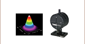
- Thermal position and energy sensors incorporate four thermopiles arranged as quadrants of a square. By comparing the voltage output from each quadrant, the unit calculates the beam's position.
- Energy sensors are based on the pyroelectric effect. They deliver a voltage peak proportional to the pulse energy. If an energy sensor is recognized, the console will use a peak voltage detector, and the pulse energy will be calculated from the sensor's responsivity.
The consoles and interfaces are also capable of providing a readout of the current or voltage delivered by the sensor. Select models also feature an analog output.
Consoles
| Item # | PM100A | PM100D2 | PM100D3 | PM400 | PM5020 |
|---|---|---|---|---|---|
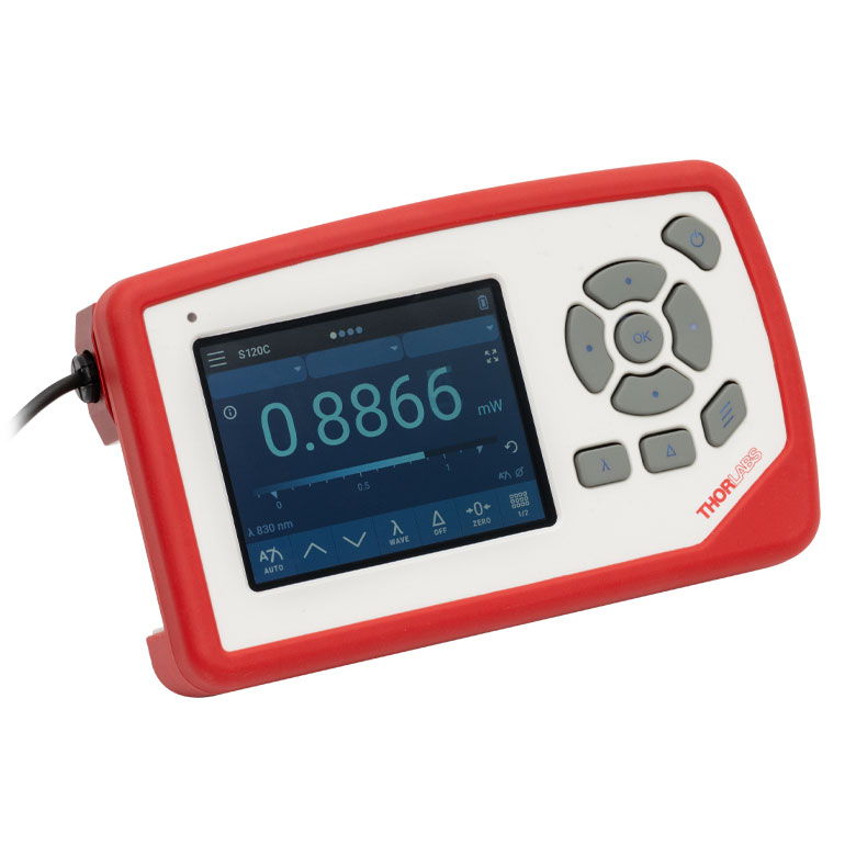
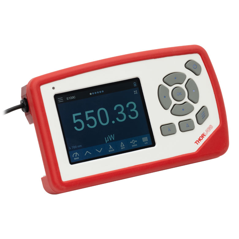
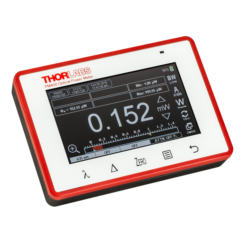
| (Click Photo to Enlarge) |  |
 |
 |
 |
 |
| Sensor Compatibility (Sensors Not Included) | |||||
| Photodiode Power |  |
|
|
|
|
| Thermal Power | |
|
|
|
|
| Thermal Position & Power | - | - | |
|
|
| Pyroelectric Energy | - | |
|
a |
|
| Key Features | |||||
| Housing Dimensions (H x W x D) |
7.24" x 4.29" x 1.61" (184 mm x 109 mm x 41 mm) |
6.42" x 3.87" x 1.38" (163.0 mm x 98.4 mm x 35.0 mm) |
5.35" x 3.78" x 1.16" (136.0 mm x 96.0 mm x 29.5 mm) |
9.97" x 4.35" x 11.56" (253.2 mm x 110.6 mm x 293.6 mm) |
|
| Channels | 1 | 2 | |||
| External Temperature Sensor Input (Sensor Not Included) | - | - | Readout and Record Temperature Over Time | ||
| External Humidity Sensor Input (Sensor Not Included) | - | - | Readout and Record Humidity Over Time | ||
| Analog Outputb | Amplified Input Signal, SMA, 0 to 2 V, Up to 100 kHz |
Amplified Input Signal or 12-bit DAC Corrected Input Signal, SMA, 0 to 2.5 V, Up to 100 kHz |
Amplified Input Signal, 12-bit DAC Corrected Input Signal, or 14-bit DAC Corrected X-Y Position Signal, SMA, 0 to 2.5 V (Power); -2.0 to 2.0 V (Position), Up to 100 kHz |
Amplified Input Signal or DAC Corrected Input Signal, 2p Audio 3.5 mm (Adapter to BNC included), 0 to 2 V, Up to 100 kHz |
Amplified Input Signal or DAC Corrected Input Signal, 2 x BNC, -2.5 to 10 V, Up to 250 kHz. Programmable AOc, 4 x BNC, -5 to 10 V, Up to 1 kHz |
| Input/Output Ports | - | 26-Pin AUX Connector With 4 GPIO, AN OUT for Power (Analog Input Signal and 12-bit DAC) and Position Sensor (14-bit DAC), I2C, UART, and Analog and Digital Supply Voltages | 14-Pin AUX Connector With 4 GPIO, Programmable, 2 x 10 bit ADC for External Temperature, Relative Humidity Sensor, +3.3 V, ±2.5 V (100 mA Max) |
10-Pin PCB Connector, 4 Configurable Digital I/O Channels, 1 Trigger In/Out, I2C (LVTTL / TTL) |
|
| Shutter Control | - | - | - | - | Support for SH05R(/M) or SH1(/M) Optical Shutter with Interlock Input |
| Fan Control | - | - | - | - | |
| Source Spectral Correction | - | ||||
| Attenuation Correction | - | ||||
| External Trigger Input | - | - | - | ||
| Display | |||||
| Type | Mechanical Needle and LCD Display with Digital Readout | 3.5" Full Color Touchscreen Display, 640 x 480 Pixels | 4.3" Protected Capacitive Touchscreen with Color Display, 400 x 272 Pixels | 5" IPS Touchscreen LCD Display, 854 x 480 Pixels | |
| Dimensions | Digital: 1.9" x 0.5" (48.2 mm x 13.2 mm) Analog: 3.54" x 1.65" (90.0 mm x 42.0 mm) |
2.80" x 2.10" (71.0 mm x 53.3 mm) |
3.7" x 2.1" (95 mm x 54 mm) |
4.32" x 2.43" (109.7 mm x 61.6 mm) |
|
| Refresh Rate | 20 Hz | 50 Hz | 10 Hz (Numerical) 25 Hz (Analog Simulation) |
25 Hz | |
| Measurement Viewsd | |||||
| Numerical | |||||
| Mechanical Analog Needle | - | - | - | - | |
| Simulated Analog Needle | - | ||||
| Bar Graph | - | ||||
| Trend Graph | - | ||||
| Statistics | |||||
| Pass/Fail | - | - | - | - | |
| Scope | - | - | - | ||
| Memory | |||||
| Type | - | eMMC Flash | NAND Flash | SD Card | |
| Size | - | 8 GB | 4 GB | 8 GB | |
| Power | |||||
| Battery | LiPo 3.7 V 2300 mAh | LiPo 3.7 V 2300 mAh | LiPo 3.7 V 2300 mAh | - | |
| External | 5 VDC via USB or Included AC Adapter | 5 VDC via USB-C Connector | 5 VDC via USB Mini B Connector | Line Voltage: 100 - 240 V | |


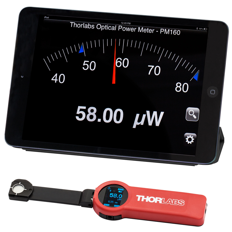
Click to Enlarge
Figure 113A The PM160 wireless power meter, shown here with an iPad mini (not included), can be remotely operated using Apple mobile devices.
This tab outlines the full selection of Thorlabs' power and energy sensors. Refer to Table 113B for power meter console and interface compatibility information.
In addition to the power and energy sensors listed below, Thorlabs also offers all-in-one, wireless, handheld power meters and compact USB power meter interfaces that contain either a photodiode or a thermal sensor, as well as power meter bundles that include a console, sensor head, and post mounting accessories.
Thorlabs offers four types of sensors:
- Photodiode Sensors: These sensors are designed for power measurements of monochromatic or near-monochromatic sources, as they have a wavelength dependent responsivity. These sensors deliver a current that depends on the input optical power and the wavelength. The current is fed into a transimpedance amplifier, which outputs a voltage proportional to the input current.
- Thermal Sensors: Constructed from material with a relatively flat response function across a wide range of wavelengths, these thermopile sensors are suitable for power measurements of broadband sources such as LEDs and SLDs. Thermal sensors deliver a voltage proportional to the input optical power.
- Thermal Position & Power Sensors: These sensors incorporate four thermopiles arranged as quadrants of a square. By comparing the voltage output from each quadrant, the unit calculates the beam's position.
- Pyroelectric Energy Sensors: Our pyroelectric sensors produce an output voltage through the pyroelectric effect and are suitable for measuring pulsed sources, with a repetition rate limited by the time constant of the detector. These sensors will output a peak voltage proportional to the incident pulse energy.
| Table 113B Console Compatibility | |||||||||
|---|---|---|---|---|---|---|---|---|---|
| Console Item # | PM100A | PM100D2 | PM100D3 | PM400 | PM5020 | PM101 Series |
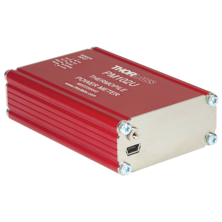
PM102 Series |
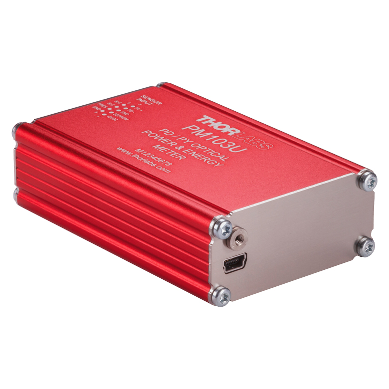
PM103 Series |
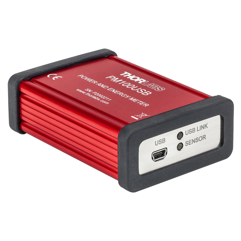
PM100USB |
| Photodiode Power | |
|
|
|
|
|
- | |
|
| Thermal Power | |
|
|
|
|
|
|
- | |
| Thermal Position | - | - | |
|
|
- | |
- | - |
| Pyroelectric Energy | - | |
|
a |
|
- | - | |
a |
Power and Energy Sensor Selection Guide
There are two options for comparing the specifications of our Power and Energy Sensors. Tables 113C, 113D, 113E, and 113F sort our sensors by type (e.g., photodiode, thermal, or pyroelectric) and provide key specifications.
Alternatively, the selection guide Figures 113G and 113H arrange our entire selection of photodiode and thermal power sensors by wavelength (Figure 113G) or optical power range (Figure 113H). Each box contains the item # and specified range of the sensor. These graphs allow for easy identification of the sensor heads available for a specific wavelength or power range.
| Table 113C Photodiode Power Sensors |
|---|


| Table 113D Thermal Power Sensors |
|---|


| Table 113E Thermal Position & Power Sensors |
|---|


| Table 113F Pyroelectric Energy Sensors |
|---|


 Figure 113G Sensor Options Arranged by Wavelength Range
 Figure 113H Sensor Options Arranged by Power Range
Pulsed Laser Emission: Power and Energy Calculations

Determining whether emission from a pulsed laser is compatible with a device or application can require referencing parameters that are not supplied by the laser's manufacturer. When this is the case, the necessary parameters can typically be calculated from the available information. Calculating peak pulse power, average power, pulse energy, and related parameters can be necessary to achieve desired outcomes including:
- Protecting biological samples from harm.
- Measuring the pulsed laser emission without damaging photodetectors and other sensors.
- Exciting fluorescence and non-linear effects in materials.
Pulsed laser radiation parameters are illustrated in Figure 170A and described in Table 170B. For quick reference, a list of equations is provided below. The document available for download provides this information, as well as an introduction to pulsed laser emission, an overview of relationships among the different parameters, and guidance for applying the calculations.
|
Equations: |
||||
 |
and |  |
||
 |
||||
 |
||||
 |
||||
Peak power and average power calculated from each other: |
||||
 |
and |  |
||
| Peak power calculated from average power and duty cycle*: | ||||
 |
*Duty cycle ( ) is the fraction of time during which there is laser pulse emission. ) is the fraction of time during which there is laser pulse emission. |
|||
Click to Enlarge
Figure 170A Parameters used to describe pulsed laser emission are indicated in this plot and described in Table 170B. Pulse energy (E) is the shaded area under the pulse curve. Pulse energy is, equivalently, the area of the diagonally hashed region.
| Table 170B Pulse Parameters | |||||
|---|---|---|---|---|---|
| Parameter | Symbol | Units | Description | ||
| Pulse Energy | E | Joules [J] | A measure of one pulse's total emission, which is the only light emitted by the laser over the entire period. The pulse energy equals the shaded area, which is equivalent to the area covered by diagonal hash marks. | ||
| Period | Δt | Seconds [s] | The amount of time between the start of one pulse and the start of the next. | ||
| Average Power | Pavg | Watts [W] | The height on the optical power axis, if the energy emitted by the pulse were uniformly spread over the entire period. | ||
| Instantaneous Power | P | Watts [W] | The optical power at a single, specific point in time. | ||
| Peak Power | Ppeak | Watts [W] | The maximum instantaneous optical power output by the laser. | ||
| Pulse Width |  |
Seconds [s] | A measure of the time between the beginning and end of the pulse, typically based on the full width half maximum (FWHM) of the pulse shape. Also called pulse duration. | ||
| Repetition Rate | frep | Hertz [Hz] | The frequency with which pulses are emitted. Equal to the reciprocal of the period. | ||
Example Calculation:
Is it safe to use a detector with a specified maximum peak optical input power of 75 mW to measure the following pulsed laser emission?
- Average Power: 1 mW
- Repetition Rate: 85 MHz
- Pulse Width: 10 fs
The energy per pulse:

seems low, but the peak pulse power is:

It is not safe to use the detector to measure this pulsed laser emission, since the peak power of the pulses is >5 orders of magnitude higher than the detector's maximum peak optical input power.
Figure 796A DAkkS-accredited calibrations are performed in accordance with DIN EN ISO/IEC 17025:2018.
Recalibration Services
Thorlabs offers two types of recalibration services in-house for our power and energy meter electronics and photodiode power sensors: ISO 17025 accredited calibrations and manufacturer calibrations. Only the manufacturer calibration is available for the NS170C microscope slide peak power sensor, our thermal power sensors, and our pyroelectric energy sensors. All new products are delivered with a manufacturer calibration by default; if an ISO 17025 accredited calibration is desired for a new device, please contact Tech Sales.
ISO 17025 accredited calibrations are performed in-house in accordance with DIN EN ISO/IEC 17025:2018. Thorlabs GmbH's calibration laboratory is accredited by the German Accreditation Body (DAkkS), the national accreditation authority of the Federal Republic of Germany. The scope of services is described here in English or German. Accredited calibrated power and/or energy meter electronics come with a dedicated certificate of calibration proving the specified accuracy and traceability of calibration data. This certification may be required in certain applications or industries, such as the medical market.
In contrast, our manufacturer calibrations are subject to the quality management requirements of ISO 9001. The certificate of calibration lists the equipment used for the calibration procedure as well as the calibration data acquired. The manufacturer calibration of a power sensor includes recalibration of a single-channel console or interface at no additional cost. If you wish to calibrate one or more sensors with a dual-channel console, each sensor and console calibration service will need to be purchased individually.
Both types of calibration can be offered for third-party equipment or adjusted for special requirements upon request. Please reach out to Tech Sales for further details.
We recommend recalibrating your Thorlabs sensor and console as a pair; however, each may be recalibrated individually. To ensure accurate measurements, we recommend recalibrating annually. To order one or more sensor recalibrations with a dual-channel console, we offer two options: either 1) fill out the Returns Material Authorization (RMA) form with each console and sensor Item # to be recalibrated and specify either manufacturer calibration or ISO 17025 accredited calibration in the "Further Details" field, or 2) separately add each recalibration service Item # offered below to your cart.
| Posted Comments: | |
YN K
(posted 2025-05-19 13:24:20.703) Subject: Suitability of S425C and S130C for Measuring 390 nm SHG Output
I generated a 390 nm beam via second harmonic generation (SHG) using a 780 nm pulsed laser. While the 780 nm fundamental beam is clearly detectable, the 390 nm beam does not produce any measurable response on the S425C sensor.
I also tested the 390 nm output using the S130C photodiode sensor. Although it provides a very small reading, I understand that the S130C is only specified for use above 400 nm, so I am unsure whether the measurement is reliable.
Could you please confirm whether the S425C and S130C sensors are appropriate for measuring 390 nm light? If not, could you recommend a suitable sensor model for this wavelength?
Thank you for your assistance. hkarpenko
(posted 2025-05-19 11:33:49.0) Dear customer,
thank you for your feedback. The S425C sensor is designed for higher power applications and can detect signals from 2mW within a wavelength range of 190nm - 20µm at a temperature stable lab environment. Your generated signal might be too small to be detected. I will contact you directly to discuss your application in detail with you. user
(posted 2024-11-13 15:11:28.17) Is S401C appropriate to measure 10Hz ns laser pulse at 355nm? expected pulse energy is 10 µJ ~ 1mJ corresponding to the 0.1 ~ 10 mW average power. The beam spot is ~ 5mm x 5mm. I expect 1 percent resolution since the stated resolution is 1 µW. hkarpenko
(posted 2024-11-13 08:14:38.0) Dear customer,
thank you for your feedback.
It´s not possible to measure the average power directly with the S410C and your laser parameters. The problem is the low repetition rate of 10Hz, which the sensor is still capable of following. However you could take a record over a period of time and estimate the average power from that. This can be done within the optical power monitor software. I contact you directly to discuss this further with you. Manuel Jerez
(posted 2024-07-08 11:01:44.22) Good afternoon,
We have tried to measure optical power with your S401C device, as follows: An optical fibre faces the sunlight, guiding the radiation to the photodetector, which is located in a thermally insulated room. The results we get are very strange, with sudden drops in the measurement, and very irregular values. Is there any reason why this might happen? Thank you hchow
(posted 2024-07-09 03:17:15.0) Dear Mr. Jerez, thank you for your enquiry. Depending on how much light is coupled through your fiber into the S401C, you could possibly expect huge fluctuations in the measured optical power. This is due to unstable turbulent nature of the earth's lower atmosphere which can cause the amount of light making it through to the ground to be unstable at best. In any case, I will reach out to you in a separate email to address your concerns. Thank you. user
(posted 2024-06-13 09:14:29.643) Question about the S425C-L:
Do you have data on the change in the absorbance as a function of ambient temperature (I am specifically interested in 780 nm and 1560 nm).
Could it be that e.g. the sensor overestimates the power at 780 nm by a few percent while underestimating the power at 1560 nm (in two separate measurements)? In order words, can the calibrated absorbance curve be "tilted" to lower or higher wavelengths compared to the correct absorbance curve? hchow
(posted 2024-06-14 06:06:28.0) Dear User, no unfortunately we do not have any data with respect to absorbance versus ambient temperature. With an increase in ambient temperature, the sensitivity of the thermopile sensor decreases. The sensitivity given as volt per absorbed radiation is lower at higher ambient temperatures. The consequence of which is that the whole sensitivity curv is shifted at different voltage levels depending upon the ambient temperature. Thus, the gradient of the curves (which is proportional to the thermopile sensitivity) decreases with increasing ambient temperature. Our thermopile sensors are calibrated at room temperature, so any sharp increase or decrease in temperature will cause issues with the voltage reading. The absorbance coating does play role in the amount of transmitted heat being converted into voltage, but this is counteracted through our calibration process and the responsivity values recorded on the EEPROM chip of our thermal sensors. PHAM VU
(posted 2022-10-26 19:04:24.527) I have bought PM100USB (SN 1914996) and the sensor S302C (SN M00794496) but it lack of calibration certificate.
Could you please help check and provide it?
Thank and regards,
Vu hchow
(posted 2022-10-27 04:26:56.0) Dear Mr. Vu, thank you for your enquiry. I will personally reach out to you to provide this information. Thank you. Andrey Kuznetsov
(posted 2022-10-21 12:48:23.04) Can you please update the website with all the products' Responsivity V/W? hchow
(posted 2022-10-25 08:09:47.0) Dear Mr. Kuznetsov, thank you for your enquiry. We do offer an analog to the responsivity graphs that you see for our photodiode sensors, and they are the absorbance versus wavelength graphs. I will personally reach out to you for more information. Jimm Wu
(posted 2022-02-12 00:23:41.467) Hi,
Can I ask several questions?
1. Is this item only the head? Does itself work to give the intensity of the light?
2. Where to get the intensity value because I don't see any viewing screen?
3. Does this head give the light intensity in the unit W/cm2 or mW/cm2?
4. Do I need to order other accessories to work together with this head?
Thank you very much for answering my questions, these questions are very important for my research. I just want to find a good sensor for my research. I saw this device in one published publications, so I think it should be ideal for my research.
I will appreciate it if you can respond to me as soon as possible. soswald
(posted 2022-02-15 06:50:30.0) Dear Jimm Wu,
thank you for your feedback.
The S302C is indeed only the sensor head and for readout a power meter console (https://www.thorlabs.de/newgrouppage9.cfm?objectgroup_id=3341) or interface (https://www.thorlabs.de/newgrouppage9.cfm?objectgroup_ID=4037) is required.
The head measured the optical power in W. Conversion to an irradiance in W/cm² or mW/cm² requires that you know the beam diameter incident on the sensor.
I have reached out to you directly to discuss your application in more detail. 程生 程
(posted 2021-11-03 02:05:49.85) S314价格多少? YLohia
(posted 2021-12-23 11:20:53.0) Thank you for contacting Thorlabs. An applications engineer from our team in China (techsupport-cn@thorlabs.com) has reached out to you directly regarding this. Ronald Sipkema
(posted 2020-07-14 09:06:51.93) L.S.,
I'm interested in using the S425C in combination with either a PM101 or PM100USB for OEM use / integration into a machine. Is it possible to order the sensor with a different cable length or alternatively shorten or lengthen the fixed cable attached to the sensor head ourselves? What would be practical limits on the cable length from sensor to meter?
Similarly the PM16-425 might also be an interesting solution, except for the fixed cable length and the fact that the combined electronics / USB plug probably won't fit through a cable carrier or cable hose. Are there options for changing cable length on those sensors? dpossin
(posted 2020-07-16 08:23:45.0) Dear Ronald,
Thank you for your feedback. We did not test at what length the data transfer does not work any more but up to 3m works for sure. We can either offer special power heads with longer cables or you lengthen the cable yourself. The cable of the USB powermeter PM16-425 can be easily extended by a USB to USB extension cable. Alp Ucak
(posted 2020-06-26 12:09:54.14) Hello, at our laboratory, we are using S350C to measure power. Our beam diameter is about 3mm fwhm and the average power is 25W with 350fs laser pulses. At our measurements, we observe an initial rise and we suspect of the powermeter heating problems. It is getting about 45 celsius degrees. Does that create a problem? Should we use a fan or is there another solution? dpossin
(posted 2020-07-02 10:02:19.0) Dear Alp,
Thank you for your feedback. Most probably the average power of your laser is too high which leads to the fact that the heat sink is not able to dissipate all the heat. I am reaching out to you in order to provide further help. Joseph Donovan
(posted 2019-09-18 08:11:55.98) Hi,
I was wondering if the surface of the S425C-L can tolerate short pulsed sources well (the S370C doesn't have enough power handling for our needs).
The laser we're using is 1035 nm, max. power 60W (though will be mostly used around 20W), ~300fs pulses at 1MHz, ~3mm beam diameter. dpossin
(posted 2019-09-20 02:49:18.0) Dear Joseph,
Thank you for your feedback. We do not tested this but we have at least one customer who uses our high power thermal sensors in the fs regime at a pulse peak power of 0.1 MW. At the repetition rate you would like to use the laser, the operating mode can be seen as quasi CW (continues wave). In case you want to use the laser at a average power of 20W you will get a pulse peak power of about 67 MW. At 20W, the heat dissipation should be no problem but I am a bit concerned if the absorption layer on the detector surface can survive the high peak power. Andrey Kuznetsov
(posted 2019-04-11 21:31:28.367) What are the noise figures for all the products in units of Watts? This would help to choose a meter based on how sensitive the measurement can be while not being overpowered by the noise. nreusch
(posted 2019-04-18 05:04:50.0) This is a response from Nicola at Thorlabs. Thank you for your suggestion! The optical power range specification in combination with the resolution (both specified in Watts) should allow you to determine whether your optical signal can be detected. These features contain all limiting factors including noise. gizem.alpakut
(posted 2019-01-22 08:00:48.627) Hi, I have a question regarding S425C-L and S121C pwoermeter sensors. Whenever I measure a specific power value using both of them, I always get different results. S425C-L always gives 50% less power value than S121C does. I am well aware that S425C-L is a thermal power sensor and other is a photodiode, I used PM100D and PM100USB as power meter consoles, which automatically recognize the console type. What can be the resson for that difference? Is there a way to fix this problem? Thanks in advance. nreusch
(posted 2019-01-23 10:50:02.0) This is a response from Nicola at Thorlabs. Thank you very much for your inquiry. You are right about the fact that such differences are mostly due to the different nature of both sensors. This is especially the case for e.g. broadband sources, for larger angles of incidence (relevant for the photodiode sensor) or for pulsed sources. I will get back to you directly to discuss your specific application. spanna
(posted 2018-12-30 14:08:20.63) Dear Thorlabs, I have two questions regarding the S425C-L model:
1. Below what power I can safely remove the heatsink, my laser provides 6mJ (6W @ 1kHz rep.rate) 35fs pulses with 11mm full width 1/e2 spot size?
2. Does the heatsink removal affect the detector calibration or its reading in any way?
Thanks in advance swick
(posted 2019-01-08 04:00:56.0) This is a response from Sebastian at Thorlabs. Thank you for the inquiry.
1. When measuring low optical powers we recommend for stability reasons to use thermal detectors with heat-sinks.
Removing the heat sink provides the option to use other type of heat-sinks like water-cooling.
2. Calibration should not be affected if heat-sink is replaced with an other appropriate one.
I contacted you directly for further discussion. cwong3
(posted 2017-01-16 18:00:18.07) Hi there. Can you tell me what the max energy density would be for a 30 fs pulse? I'm mostly interested in the S470C and S310C. Thanks. wskopalik
(posted 2017-01-17 05:13:38.0) This is a response from Wolfgang at Thorlabs. Thank you very much for your inquiry.
Unfortunately, we don't have specifications for the maximum energy density for fs pulses. Depending on the exact laser parameters (wavelength, pulse energy, repetition rate, etc.) one of our sensors might however still be suitable.
I have contacted you directly to further discuss your requirements and to look for a suitable sensor. arkke.eskola
(posted 2016-10-27 12:06:48.73) Hi,
I am searching a (thermal) sensor, which would work both with excimer laser (193, 248, and 351 nm) and Nd:YAG laser (213, 266, 355, and 532 nm). I am thinking your S350C sensor due to its large aperture size and wide wavelenght range. Could you please comment its suitability for this purpose; especially I would like to know whether there might appear any issue(s) to use S305C to measure (short) Nd:YAG laser pulse energies. Or should I think about pyroelectric energy sensors?
Thanks,
Arkke Eskola wskopalik
(posted 2016-10-28 05:19:58.0) This is a response from Wolfgang at Thorlabs. Thank you for your inquiry.
Thermal sensors are generally a good choice to measure the average power of pulsed lasers. It depends on the exact laser parameters which sensor model is the most suited (i.e. wavelength, pulse energy, pulse width, repetition rate, beam diameter). These parameters are necessary to make sure that the sensor can handle the power levels of the laser and will not be damaged by it.
I will contact you directly to further discuss your requirements. kedves
(posted 2016-04-13 18:29:51.247) Hello, I am looking for a power meter for a femtosecond laser of about 25 mJ pulse energy, 10 Hz repetition rate (i.e. 250 mW average power), and 40 fs pulse duration (i.e. 625 GW pulse peak power) and 15 mm pulse diameter. Which of your products would you recommend that can tolerate this high peak power too? shallwig
(posted 2016-04-14 10:34:42.0) This is a response from Stefan at Thorlabs. Thank you very much for your inquiry. At the moment we have no sensor available which is specified to stand 625 GW peak power and 353,7 GW/cm2 peak power density. I will contact you directly to discuss if there is a special solution we can offer. mastron
(posted 2016-02-24 19:42:46.833) I am looking into power meters and sensors for measurements of ultrafast pulsed lasers (pulses <250fs at 1khz). Would the S470C be appropriate for this kind of measurement? I wouldn't need shot-to-shot resolution; just to be able to measure pulse energies in several ranges: low uJ (so at 1 khz, low mW range), ~500mW, and ~2W without damaging the power sensor. Also, are calibration options available for multiple wavelength regions? I'd like to be able to measure visible, 800 nm, and near to mid-IR (so around 1.5, 2, 5, and 6 um) accurately. shallwig
(posted 2016-02-25 10:16:16.0) This is a response from Stefan at Thorlabs. Thank you very much for your inquiry due to its long response time (<2s) as typical for thermal sensors average power measurements of pulsed sources are possible. The calibration and measurement uncertainty of this sensor are specified from 250nm – 10,6µm. More information about the calibration of our thermal heads can be found in the power meter tutorial in the “calibration “ Tab here: http://www.thorlabs.com/newgrouppage9.cfm?objectgroup_id=6188
I will contact you directly to discuss your application and your parameters in more detail. user
(posted 2015-12-16 15:42:00.627) In addition to my question below, would you please advice me if you conducted calibration with any emmersion oil? How would it be calibrated with angled beam? shallwig
(posted 2015-12-16 05:09:11.0) This is a response from Stefan from Thorlabs. Thank you again for your for your inquiry. We calibrate the sensor S175C at 1064nm with a collimated laser at 100mW, the beam hits the sensors surface perpendicular. Apart from the calibration at 1064nm we do perform a reflectivity measurement were the reflectivity of the coating gets measured from 266 – 1064nm .
In our power meter tutorial the whole process gets described in detail: http://www.thorlabs.com/newgrouppage9.cfm?objectgroup_id=6188
We have a NIST traceable reference built in a integrating sphere and measure the spectral intensity distribution. Afterwards we put the sensor under test in and measure the spectral reflectivity again. The difference between both curves tells us about the reflectivity of the sensors absorber surface. This is the calibration curve you also get delivered with the sensor.
But there is no NIST standard available which allows to calibrate the sensors with angled beams so far. Therefore we cannot specify any measurement accuracy for this measurement task. user
(posted 2015-12-16 13:57:56.547) I am interested in you S175C sensor to measure oure Ti:Sa laser under 20X objective(oil emmersion). We can't know about real power under the objective as we have not had any sensor. But guessing it would be 500mW-less than 1W. Can we use your S175C for our measurment? shallwig
(posted 2015-12-16 04:37:05.0) This is a response from Stefan at Thorlabs. Thank you very much for your inquiry. For estimation how suitable this sensor is for power measurement of your Ti:Sa I would need further information about the beam. We specify for the sensor a maximum average power density of 200W/cm2 and for µs Pulses and a max pulse energy density of 0.1J/cm2 and 1J/cm2 for 1ms pulses. You can find these information in the spec sheet: http://www.thorlabs.de/thorcat/MTN/S175C-SpecSheet.pdf
The measurement accuracy we specify is only valid for parallel beams with diameter >1mm. I would like to discuss your application in more detail with you directly, unfortunately you left no email address. Please feel free to contact me at europe@thorlabs.com hsynvnvural
(posted 2015-11-20 09:55:12.33) Is there any difference between CW/Pulsed Laser average power measurement for thermopile sensors? Is the uncertainty same for both measurement for S350C and S470C sensors? shallwig
(posted 2015-11-20 10:09:03.0) This is a response from Stefan at Thorlabs. Thank you very much for your inquiry. In general Thermopile sensors have a very slow response time, for the S470C we specify <2s. Depending on the repetition rate of your pulsed source multiple of pulses will hit the active surface before a measurement point is taken. The measurement uncertainty for the S350C and S470C can be found in the specs table: ±3% @ 351 nm; ±5% @ 190 - 1100 nm (S350C) and ±3% @ 1064 nm; ±5% @ 250 nm - 10.6 µm (S470C)
A main difference apart from the power range is the detector type. The S350C is a thermal surface absorber while the S470C is a thermal volume absorber. Thermal volume absorbers have significantly higher responsivities, which allow them to detect very low power levels and short (ns) pulses. However, this improvement usually comes at the expense of response time. I will contact you directly to check which sensor is suited for your application. Paul.taylor
(posted 2015-03-20 11:12:45.53) Can you read the voltage direct from the head via a Plc analog input card? If so - what rough calibration V/W is it? shallwig
(posted 2015-03-23 06:13:37.0) This is a response from Stefan at Thorlabs. Thank you very much for your inquiry. You can use a PLC analog input card to read out the voltage directly by taking the generated thermo voltage from Pin 3 and 8 of the D-Sub connector. Please take a look into the “Pin Diagrams” Tab on the website http://www.thorlabs.com/NewGroupPage9.cfm?ObjectGroup_ID=3333 With the sensor head you will get a calibration certificate where the sensitivity at our calibration sources (1062nm) is listed with an uncertainty of +/-3%.
Depending on which sensor you are interested in the sensitivity is between 0,1mV/W and about 100mV/W. Thus you have to deal with very small voltages. Further information about how our thermal sensors get calibrated can be also found in the power meter tutorial on our website: http://www.thorlabs.com/newgrouppage9.cfm?objectgroup_id=6188 in the “calibration” tab. I will contact you directly to discuss your application in more detail. tonyhongxp
(posted 2015-02-10 22:20:54.77) would the thermal power meter work below 190 nm? The absorption curve does not seem to fall at wavelength below 190 nm. tschalk
(posted 2015-02-11 08:03:01.0) This is a response from Thomas at Thorlabs. Thank you very much for your inquiry. You can use the sensor below 190nm but we dont have specific informaiton about the sensitivity and we dont have the possibility to calibrate the sensor below that wavelength. I will contact you directly to discuss your application. user
(posted 2011-11-28 09:07:26.0) A response from Tyler at Thorlabs: Hello Krister, The thermal power meter sensors that Thorlabs sells use a thermopile sensor to measure the incident power. These sensors would not be an out-of-the-box solution for a non-contact temperature sensor. We will contact you to discuss your application and possible solutions. krister.magnusson
(posted 2011-11-28 05:57:45.0) This product measures light intensity. Does it also include a laser which send out a detection signal wich is analyzed? That is, how does it operate?
I am looking for a non-contact temperature sensor (not pyrometer).
Best regards,
Krister Magnusson jjurado
(posted 2011-07-08 15:18:00.0) Javier Jurado: Response from Javier at Thorlabs to last poster: We do offer a cap that you can use to cover the entrance port of the S302C sensor. The part number is SM1CP1:
http://www.thorlabs.com/NewGroupPage9.cfm?ObjectGroup_ID=3519
Please do not hesitate to contact us at techsupport@thorlabs,com if you have any further questions. user
(posted 2011-07-08 15:50:53.0) I ordered S302C and I would like protect its window. Do you sell a cap for it? jjurado
(posted 2011-06-02 11:34:00.0) Response from Javier at Thorlabs to halverso: Thank you very much for contacting us. With a maximum incident power density spec of 200W/cm^2, the S302C should work for your application. However, other parameters such as wavelength range, minimum incident power, and beam diameter are important, as well, in order to determine the most suitable sensor. I will contact you directly to discuss these details. halverso
(posted 2011-06-02 09:18:06.0) I want to measure power on a stable solar simulator. Expected value is 100mW/cm2. The S302C appears to be ideal for my purpose, but I wanted to confirm. Thanks. apalmentieri
(posted 2010-02-22 22:55:57.0) A response from Adam at Thorlabs to malayk: The S302C sensors are not compatible with the old PM100 power meters. They are compatible with the new PM100D power meter. I will contact you directly to help provide you with the best possible solution that suits your needs. malayk
(posted 2010-02-22 22:00:52.0) Is the S302C sensor compatible with the old PM100 power meter? |
| Item #a | S401C | S405C |
|---|---|---|
| Sensor Image (Click the Image to Enlarge) |
 |
 |
| Wavelength Range | 190 nm - 20 µm | 190 nm - 20 µm |
| Optical Power Range | 10 µW - 1 W (3 Wb) | 100 µW - 5 W |
| Input Aperture Size | Ø10 mm | Ø10 mm |
| Active Detector Area |
10 mm x 10 mm | 10 mm x 10 mm |
| Max Optical Power Density | 500 W/cm2 (Avg.) | 1.5 kW/cm2 (Avg.) |
| Detector Type | Thermal Surface Absorber (Thermopile) with Background Compensation |
Thermal Surface Absorber (Thermopile) |
| Linearity | ±0.5% | ±0.5% |
| Resolutionc | 1 µW | 5 µW |
| Measurement Uncertaintyd | ±3% @ 1064 nm ±5% @ 190 nm - 10.6 µm |
±3% @ 1064 nm ±5% @ 250 nm - 17 µm |
| Response Timee | 1.1 s | 1.1 s |
| Cooling | Convection (Passive) | |
| Housing Dimensions (Without Adapter) |
(1.30" x 1.69" x 0.59") |
40.6 mm x 40.6 mm x 16.0 mm (1.60" x 1.60" x 0.63") |
| Temperature Sensor (In Sensor Head) |
NTC Thermistor | NTC Thermistor |
| Cable Length | 1.5 m | |
| Post Mounting | Universal 8-32 / M4 Taps (Post Not Included) |
Universal 8-32 / M4 Taps (Post Not Included) |
| 30 mm Cage Mounting | - | Two 4-40 Tapped Holes & Two Ø6 mm Through Holes |
| Aperture Threads | Internal SM05 | Internal SM05 |
| Accessories | Internally SM1-Threaded Adapter with an Internally SM05-Threaded Light Shield |
Adapter with External SM05 and External SM1 Threads |
| Compatible Consoles | PM100A, PM100D2, PM100D3, PM400, and PM5020 | |
| Compatible Interfaces | PM101, PM101A, PM101R, PM101U, PM102, PM102A, PM102U, and PM100USB | |
- High Resolution of 1 μW or 5 μW
- S401C and S405C Have Thermistors Used to Monitor Temperature of Sensor Head
- S401C: Background Compensation for Low-Drift Measurements
- S405C: Accommodates Average Optical Power Densities Up to 1.5 kW/cm²
Click to Enlarge
Figure G1.1 S401C Thermal Sensor with Included Light Shield
Thorlabs offers two broadband thermal power sensors designed to measure low optical power sources with high resolution. Both thermal sensors' broadband coating has a flat spectral response over a wide wavelength range, as shown in Figure G1.2. The aperture size of Ø10 mm allows for easy alignment and measurement of large-spot-size laser sources. For easy integration with Thorlabs' lens tube systems and SM1-threaded (1.035"-40) fiber adapters (available below), both sensors include an externally SM1-threaded adapter.
The S401C uses active thermal background compensation to provide low-drift power measurements. This is implemented through the use of two sensor circuits to measure heat flow between the light absorber and heat sink in both directions. The measurements of the two sensor circuits are then subtracted, which minimizes the effect of thermal drift on the laser power measurement. (For information about how external thermal disturbances can affect thermal power sensor readings, please see the Operation tab.) The S401C's broadband coating offers high absorption at wavelengths between 0.19 and 20 µm (shown in Figure G1.2), which makes it ideal for use with aligning and measuring Mid-IR Quantum Cascade Lasers (QCLs). The included, internally SM05-threaded (0.535"-40) light shield is shown in Figure G1.1.
The S405C has internal SM05 (0.535"-40) threading that is directly compatible with our SM05 lens tubes, and it can also connect directly to Thorlabs' 30 mm Cage Systems.
Thorlabs offers a recalibration service for these sensors, which can be ordered below (see Item # CAL-THPY).
Click to Enlarge
Raw Data: S401C, S405C
Figure G1.2 The S405 shares the same absorption curve with the S415C, S425C, and S245C-L. (All are sold below.)
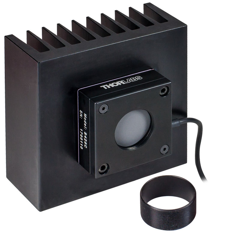
| Item #a | S415C | S425C |
|---|---|---|
| Sensor Image (Click Image to Enlarge) |
 |
 |
| Wavelength Range | 190 nm - 20 µm | 190 nm - 20 µm |
| Optical Power Range | 2 mW - 10 W (20 Wb) | 2 mW - 10 W (20 Wb) |
| Input Aperture Size | Ø15 mm | Ø25.4 mm |
| Active Detector Area |
Ø15 mm | Ø27 mm |
| Max Optical Power Density |
1.5 kW/cm² (Avg.) | 1.5 kW/cm² (Avg.) |
| Detector Type | Thermal Surface Absorber (Thermopile) | |
| Linearity | ±0.5% | ±0.5% |
| Resolutionc | 100 µW | 100 µW |
| Measurement Uncertaintyd |
±3% @ 1064 nm ±5% @ 250 nm - 17 µm |
±3% @ 1064 nm ±5% @ 250 nm - 17 µm |
| Response Timee | 0.6 s | 0.6 s |
| Cooling | Convection (Passive) | |
| Housing Dimensions (Without Adapter) |
(2.00" x 2.00" x 1.38") |
(2.00" x 2.00" x 1.38") |
| Temperature Sensor (In Sensor Head) |
NTC Thermistor | |
| Cable Length | 1.5 m | |
| Post Mounting | Universal 8-32 / M4 Taps (Post Not Included) |
Universal 8-32 / M4 Taps (Post Not Included) |
| 30 mm Cage Mounting | - | - |
| Aperture Threads | Internal SM1 | Internal SM1 |
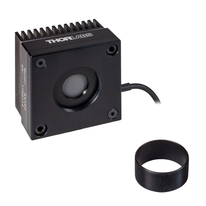
| Removable Heatsink | Yes | Yes |
| Accessories | Externally SM1-Threaded Adapter | Externally SM1-Threaded Adapter |
| Compatible Consoles | PM100A, PM100D2, PM100D3, PM400, and PM5020 | |
| Compatible Interfaces | PM101, PM101A, PM101R, PM101U, PM102, PM102A, PM102U, and PM100USB | |
- 100 µW Optical Power Resolution
- Thermistors Used to Monitor Temperature of Sensor Head
- Removable Heat Sinks Included
These thermal power sensors are designed for general broadband power measurements of low and medium power light sources. All include an externally SM1-threaded (1.035"-40) adapter, with threading concentric with the input aperture. The adapters are useful for mounting Ø1" Lens Tubes and Fiber Adapters (available below). The apertures of the S415C and S425C have internal SM1 threading.
These sensors operate with fast (<0.6 s) natural response times, and their removable heat sinks provide a high degree of flexibility to those interested in integrating them into custom setups or replacing the included heat sink with one that is water or fan cooled. If replacing the heat sink, please note that the replacement must provide heat dissipation adequate for the application.
Thorlabs offers a recalibration service for these sensors, which can be ordered below (see Item # CAL-THPY).
Click to Enlarge
Click Here for Raw Data
Figure G2.1 The absorption curves of each of the thermal power sensors designed for use with low and medium power optical sources.
Click to Enlarge
Raw Data: S350C, S425C-L, S322C
Figure G3.1 The absorption curves of each of the thermal power sensors designed for use with low and medium power optical sources.
- Thermistors Used to Monitor Temperature of Sensor Head
- S322C Has 4-40 Taps for Use with Our 30 mm Cage Systems
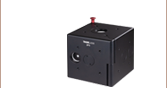
- S350C Has Ø40 mm Aperture Well Suited to Excimer and Other Lasers with Large Spot Sizes
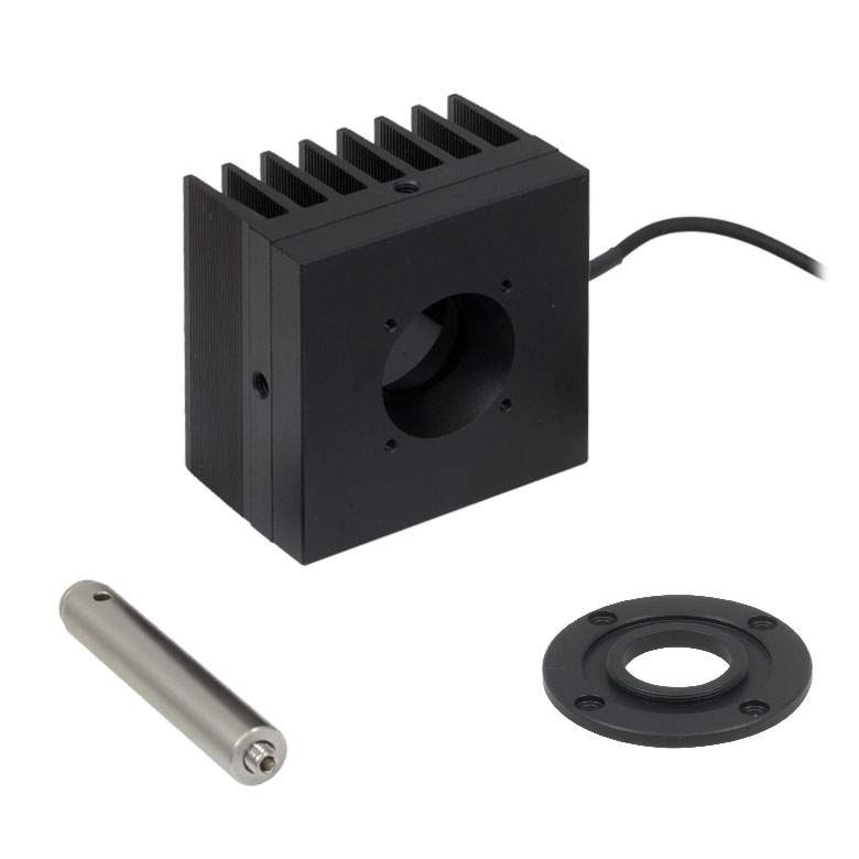
- S425C-L Features Removable Heat Sink
- S322C is Fan Cooled with an Optical Power Range Up to 200 W
These thermal power sensors are designed for general broadband power measurements of low and medium power light sources. With the exception of the S350C, all include an adapter with external SM1 (1.035"-40) threading concentric with the input aperture. This allows the sensors to be integrated into existing Ø1" lens tube systems in addition to being compatible with fiber adapters (available below). The aperture of the S425C-L has internal SM1 threading.
The S425C-L operates with a fast (<0.6 s) natural response time and has a removable heat sink, which provides a high degree of flexibility to those interested in integrating them into custom setups or replacing the included heat sink with one that is water or fan cooled. If replacing the heat sink, please note that the replacement must provide heat dissipation adequate for the application.
Thorlabs offers a recalibration service for these sensors, which can be ordered below (see Item # CAL-THPY).
| Item #a | S350C | S425C-L | S322C |
|---|---|---|---|
| Sensor Image (Click Image to Enlarge) |
 |
 |
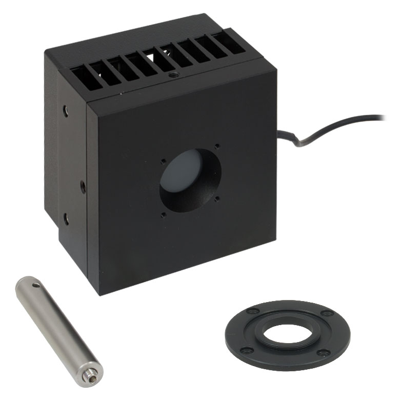 |
| Wavelength Range | 190 nm - 1.1 µm, 10.6 µm | 190 nm - 20 µm | 250 nm - 11 µm |
| Optical Power Range | 10 mW - 40 W (60 Wb) | 2 mW - 50 W (75 Wb) | 100 mW - 200 W (250 Wb) |
| Input Aperture Size | Ø40 mm | Ø25.4 mm | Ø25 mm |
| Active Detector Area |
Ø40 mm | Ø27 mm | Ø25 mm |
| Max Optical Power Density | 2 kW/cm2 (Avg.) | 1.5 kW/cm2 (Avg.) | 4 kW/cm2 (Avg., CO2) |
| Detector Type | Thermal Surface Absorber (Thermopile) | ||
| Linearity | ±1% | ±0.5% | ±1% |
| Resolutionc | 1 mW | 100 µW | 5 mW |
| Measurement Uncertaintyd | ±3% @ 1064 nm ±5% @ 190 nm - 1100 nm, 10.6 µm |
±3% @ 1064 nm ±5% @ 250 nm - 17 µm |
±3% @ 1064 nm ±5% @ 266 nm - 1064 nm |
| Response Timee | 9 s (1 s from 0 to 90%) |
0.6 s | 5 s (1 s from 0 to 90%) |
| Cooling | Convection (Passive) | Forced Air with Fanf | |
| Housing Dimensions (Without Adapter, if Applicable) |
100 mm x 100 mm x 54.2 mm (3.94" x 3.94" x 2.13") |
100.0 mm x 100.0 mm x 58.0 mm (3.94" x 3.94" x 2.28") |
100 mm x 100 mm x 86.7 mm (3.94" x 3.94" x 3.41") |
| Temperature Sensor (In Sensor Head) |
NTC Thermistor | ||
| Cable Length | 1.5 m | ||
| Post Mounting | M6 Threaded Taps, Includes Ø1/2" Post, 75 mm Long |
Universal 8-32 / M4 Taps (Post Not Included) |
M6 Threaded Taps, Includes Ø1/2" Post, 75 mm Long |
| 30 mm Cage Mounting | - | - | Four 4-40 Tapped Holes |
| Aperture Threads | - | Internal SM1 | - |
| Removable Heatsink | - | Yes | - |
| Accessories | - | Externally SM1-Threaded Adapter | Externally SM1-Threaded Adapter |
| Compatible Consoles | PM100A, PM100D2, PM100D3, PM400, and PM5020 | ||
| Compatible Interfaces | PM101, PM101A, PM101R, PM101U, PM102, PM102A, PM102U, and PM100USB | ||
| Item #a | S370C | S470C |
|---|---|---|
| Sensor Image (Click Image to Enlarge) |
 |
 |
| Wavelength Range | 400 nm - 5.2 µm | 250 nm - 10.6 µm |
| Optical Power Range | 10 mW - 10 W (15 Wb) | 100 µW - 5 W (Pulsed and CW) |
| Input Aperture Size | Ø25 mm | Ø15 mm |
| Active Detector Area |
Ø25 mm | Ø16 mm |
| Max Optical Power Density | 35 W/cm2 (Avg.); 100 GW/cm2 (Peak) | |
| Detector Type | Thermal Volume Absorber (Thermopile) | |
| Linearity | ±1% | ±0.5% |
| Resolutionc | 250 µW | 10 µW |
| Measurement Uncertaintyd | ±3% @ 1064 nm ±5% @ 400 nm - 1064 nm |
±3% @ 1064 nm ±5% @ 250 nm - 10.6 µm |
| Response Timee | 45 s (3 s from 0 to 90%) | 6.5 s (<2 s from 0 to 90%) |
| Cooling | Convection (Passive) | |
| Housing Dimensions (Without Adapter, if Applicable) |
(2.95" x 2.95" x 2.02") |
(1.77" x 1.77" x 0.71") |
| Temperature Sensor (In Sensor Head) |
N/A | N/A |
| Cable Length | 1.5 m | |
| Post Mounting | M6 Threaded Taps, Includes Ø1/2" Post, 75 mm Long |
Universal 8-32 / M4 Tap (Post Not Included) |
| 30 mm Cage Mounting | Four 4-40 Tapped Holes | - |
| Aperture Threads | - | External SM1 |
| Accessories | - | |
| Compatible Consoles | PM100A, PM100D2, PM100D3, PM400, and PM5020 | |
| Compatible Interfaces | PM101, PM101A, PM101R, PM101U, PM102, PM102A, PM102U, and PM100USB | |
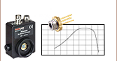
- Designed for Optical Power Measurements of Nd:YAG Lasers
- Ideal for Applications with High Peak Pulse Powers
- S370C: Ø25 mm Aperture for Large-Spot-Size Beams
- S470C: High-Sensitivity for High-Peak-Power Pulses with Low Average Power
The S370C and S470C Thermal Sensors are designed to measure short and highly energetic laser pulses. All of these units are post-mountable for free-space applications and feature NIST-traceable data stored in the sensor connector.
These thermal power sensors are unique in that they have thermal volume absorbers, where our other thermal power sensors have thermal surface absorbers. The volume absorber consists of a Schott glass filter. Incident pulses are absorbed and the heat is distributed throughout the volume. In this way, pulses that would have damaged the absorption coating of a thermal surface absorber are safely measured by these thermal volume absorbers.
The S370C features a large Ø25 mm aperture ideal for large-spot-size beams, and it is compatible with average powers from 10 mW to 10 W (CW).
In comparison, the S470C is faster, as the glass absorber volume is reduced and other design parameters have been optimized for speed. This results in a different optical power range, with the ability to measure powers down to 100 µW. The Ø15 mm aperture is of the S470C is smaller, and it has a lower max average power of 5 W. Its 10 µW resolution is better than the 250 µW resolution of the S370C.
For high-power, pulsed lasers the S370C and S470C Thermal Sensors can withstand high average and peak power densities. However, for sensors with a broader spectral range or shorter response time, consider one of our Pyroelectric Energy Sensors.
Thorlabs offers a recalibration service for these sensors, which can be ordered below (see Item # CAL-THPY).

Click to Enlarge
Click Here for Raw Data
Figure G4.1 This absorption curve is shown over a broader wavelength range than the sensors' operating ranges. See the table for the operating wavelength range of each sensor.
| Table G5.2 Specifications | |
|---|---|
| Item #a | S175C |
| Sensor Image (Click Image to Enlarge) |
 |
| Wavelength Range | 0.3 µm - 10.6 µm |
| Power Range | 100 µW - 2 W |
| Input Aperture Size | 18 mm x 18 mm |
| Active Detector Area | 18 mm x 18 mm |
| Max Optical Power Density | 200 W/cm2 |
| Detector Type | Thermal Surface Absorber (Thermopile) |
| Linearity | ±0.5% |
| Resolutionb | 10 µW |
| Measurement Uncertaintyc | ±3% @ 1064 nm; ±5% @ 300 nm - 10.6 µm |
| Response Timed | 3 s (<2 s from 0 to 90%) |
| Housing Dimensions | 76 mm x 25.2 mm x 4.8 mm (2.99" x 0.99" x 0.19") |
| Temperature Sensor (In Sensor Head) |
N/A |
| Cable Length | 1.5 m |
| Housing Features | Integrated Glass Cover Engraved Laser Target on Back |
| Compatible Consoles | PM100A, PM100D2, PM100D3, PM400, and PM5020 |
| Compatible Interfaces | PM101, PM101A, PM101R, PM101U, PM102, PM102A, PM102U, and PM100USB |
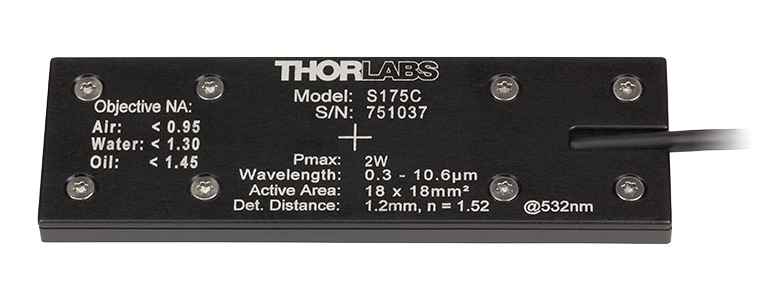
Click to Enlarge
Figure G5.1 The back of the S175C housing is engraved with the sensor specifications and a target for centering the beam on the sensor.
- Designed to Measure Optical Power at the Sample Plane of a Microscope
- 76.0 mm x 25.2 mm Footprint Matches Standard Microscope Slides
- Wavelength Range: 300 nm - 10.6 µm
- Sensitive to Optical Powers from 100 µW to 2 W
- Information Stored in Connector
- Sensor Data
- NIST- and PTB-Traceable Calibration Data
The S175C Microscope Slide Thermal Power Sensor Head is designed to measure the power at the sample in microscopy setups. The thermal sensor can detect wavelengths between 300 nm and 10.6 µm at optical powers between 100 µW and 2 W. The sensor head's 76.0 mm x 25.2 mm footprint matches that of a standard microscope slide and is compatible with most standard upright and inverted microscopes.
The thermal sensor has an 18 mm x 18 mm active area and is contained in a sealed housing behind a glass cover. An immersion medium (water, glycerol, oil) may be placed over the glass cover plate.
As seen in Figure G5.1, the bottom of the sensor housing features a laser-engraved target to aid in aligning and focusing the beam. In standard microscopes, the target can be used for beam alignment before flipping the sensor head to face the objective for power measurements. In inverted microscopes, turn on the trans-illumination lamp and align the target on the detector housing with the beam; this will center the sensor in front of the objective.
Click to Enlarge
Click Here for Raw Data
Figure G5.3 Typical absorption curve for the S175C (glass and absorber). Note that this curve is representative, and the actual absorption across the spectrum will vary from unit to unit.
Sensor specifications and the NIST- and PTB-traceable calibration data are stored in non-volatile memory in the sensor connector and can be read out by the latest generation of Thorlabs power meters. We recommend yearly recalibration to ensure accuracy and performance. Calibration may be ordered using the CAL-THPY recalibration service available below. Please contact Tech Support for more information.
To avoid damaging the sensor, we recommend positioning it in the light path at a location where the beam is not focused. It is important not to exceed the Max Optical Power Density (see Table G5.2) over the beam's spot size.
The complete set of specifications is presented in the Specs tab. Thorlabs also offers a Microscope Slide Sensor Head with a photodiode sensor for low-power, high-resolution measurements; the full presentation may be found here.
These internally SM1-threaded (1.035"-40) adapters mate terminated fiber to any of our externally SM1-threaded components, including a selection of our photodiode power sensors, our thermal power sensors, and our photodetectors.
For details on narrow versus wide key connectors, please see our Intro to Fiber tutorial. Please contact Tech Support if you are unsure if the adapter is mechanically compatible.
The APC adapters have two dimples in the front surface that allow them to be tightened with the SPW909 or SPW801 spanner wrench. The dimples do not go all the way through the disk so that the adapter can be used in light-tight applications when paired with SM1 lens tubes.
The S120-25 ferrule adapter is designed without a locking connector mechanism and accepts fiber patch cables with Ø2.5 mm ferrules for quick measurements with photodetectors or power sensors.
| Item # | S120-FC2 | S120-FC | S120-APC2a | S120-APCa | S120-SMA | S120-ST | S120-SC | S120-LC | S120-25 |
|---|---|---|---|---|---|---|---|---|---|
| Adapter Image (Click the Image to Enlarge) |
 |
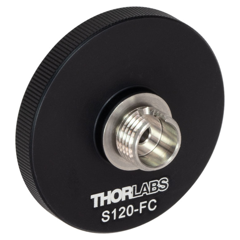 |
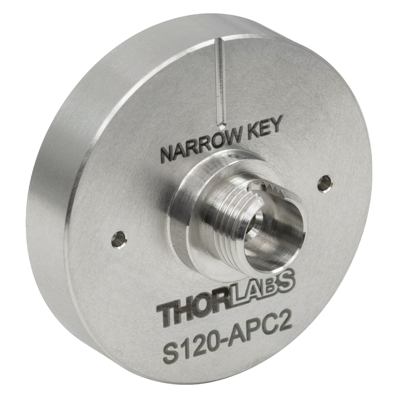 |
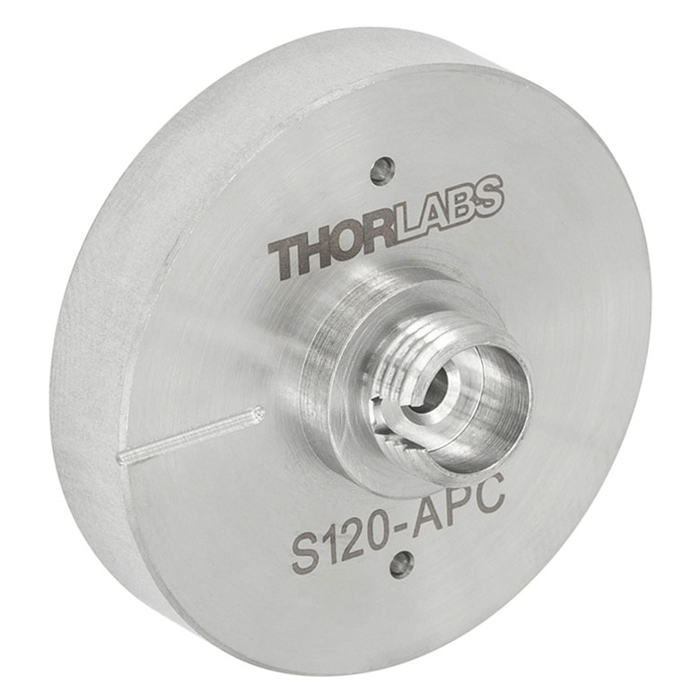 |
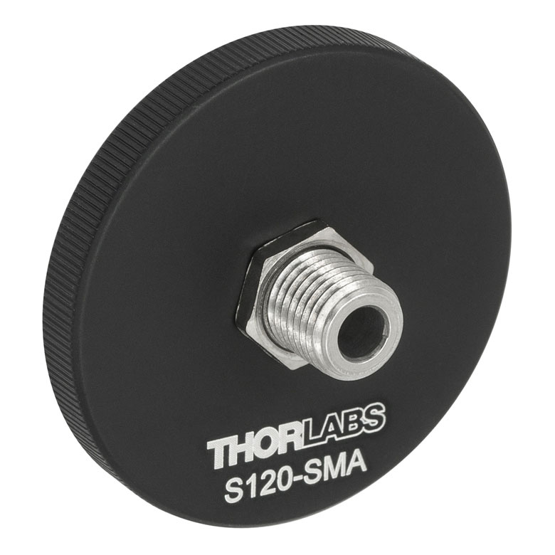 |
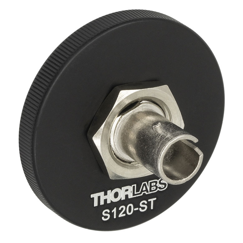 |
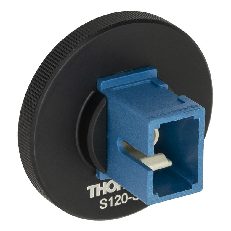 |
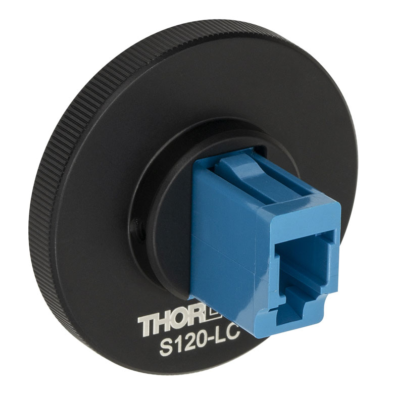 |
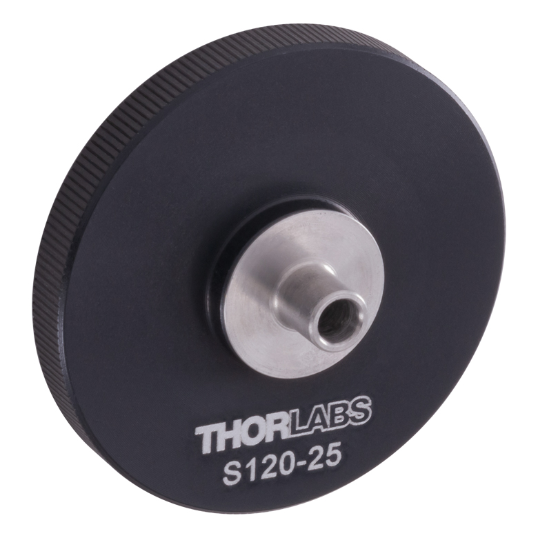 |
| Fiber Connector Type | FC/PC, 2.0 mm Narrow Key |
FC/PC, 2.2 mm Wide Key |
FC/APC, 2.0 mm Narrow Key |
FC/APC 2.2 mm Wide Key |
SMA | ST®b/PC | SC/PCc | LC/PC | Ø2.5 mm Ferrule |
| Threading | Internal SM1 (1.035"-40) | ||||||||
| Table 317A Compatibility | |
|---|---|
| Sensor Type | Sensor Item #s |
| Thermal Power | S175C, S302Ca, S305Ca, S310Ca, S314Ca,S322C, S350C, S370C, S401C, S405C, S415C, S425C, S425C-L, S470C, PM160T, PM160T-HP, PM16-401, PM16-405 |
| Pyroelectric Energy | ES111C, ES120C, ES145C, ES220C, ES245C, ES308C, ES312C, ES408C, ES412C |
Thorlabs offers recalibration services for our Thermal Power and Pyroelectric Energy Sensors. To ensure accurate measurements, we recommend recalibrating the sensors annually. Recalibration of a single-channel power and/or energy meter console or interface is included with the recalibration of a sensor at no additional cost. If you wish to calibrate one or more sensors with a dual-channel console, each sensor and console calibration service will need to be purchased individually.
Please note that the CAL-THPY recalibration service cannot be used for our Thermal Position & Power Sensors; recalibration for these sensors can be requested by contacting Tech Support. Table 317A lists the sensors for which the CAL-THPY recalibration service is available.
Requesting a Calibration
Thorlabs provides two options for requesting a calibration:
- Complete the Returns Material Authorization (RMA) form. When completing the RMA form, please enter your name, contact information, the Part #s, and the Serial #s of all sensors or consoles being returned for calibration; in the Reason for Return field, select "I would like an item to be calibrated." All other fields are optional. Once the form has been submitted, a member of our RMA team will reach out to provide an RMA Number, return instructions, and to verify billing and payment information.
- Enter the Part # and Serial # of the item that requires recalibration below and then Add to Cart. If you would like a console calibrated with your sensor, repeat this process for Item # CAL-PM1 or CAL-PM2 below, entering the console Item # and Serial #. A member of our RMA team will reach out to coordinate the return of the item(s) for calibration. Note that each console calibration Item # represents the cost of calibrating a console alone; if requesting a single-channel console calibration with a sensor calibration, the appropriate discount will be applied when your request is processed. Should you have other items in your cart, note that the calibration request will be split off from your order for RMA processing.
Please Note: To ensure your item being returned for calibration is routed appropriately once it arrives at our facility, please do not ship it prior to being provided an RMA Number and return instructions by a member of our team. Pyroelectric energy sensors returned for recalibration or servicing must include the separate BNC to DB9 adapter, which contains the sensor EEPROM.
| Table 719A Compatibility | |
|---|---|
| Calibration Service Item # | Compatible Consoles & Interfaces |
| Single-Channel | |
| CAL-PM1 | PM100D2, PM100D3, PM100A, PM400, PM100USB, PM100Da PM101 Series, PM102 Series, PM103 Series |
| Dual-Channel | |
| CAL-PM2 | PM5020 and PM320Ea |
These traceable recalibration services are for the power and/or energy meter electronics of our consoles and interfaces. To ensure accurate measurements, we recommend recalibrating annually. The manufacturer calibration of a power sensor includes recalibration of a single-channel console or interface at no additional cost; this is unavailable for the accredited calibration option. If you wish to calibrate one or more sensors with a dual-channel console, each sensor and console calibration service will need to be purchased individually. For more details on these recalibration services, please click the Documents (![]() ) icons below.
) icons below.
Table 719A lists the power and/or energy meter consoles and interfaces that can be calibrated using the CAL-PM1 and CAL-PM2 recalibration services.
Requesting a Calibration
Thorlabs provides two options for requesting a calibration:
- Complete the Returns Material Authorization (RMA) form. When completing the RMA form, please enter your name, contact information, the Part #, and the Serial # of each item being returned for calibration; in the Reason for Return field, select "I would like an item to be calibrated." In the Further Details field, please indicate "Manufacturer Calibration" or the desired calibration part number below in order to differentiate from the ISO 17025 accredited calibration option. Once the form has been submitted, a member of our RMA team will reach out to provide an RMA Number, return instructions, and to verify billing and payment information.
- Select the appropriate Item # below, enter the Part # and Serial # of the item that requires recalibration, and then Add to Cart. If you would like to calibrate one or more sensors with your console, repeat this process for the appropriate sensor recalibration service above, entering the console Item # and Serial #. A member of our RMA team will reach out to coordinate return of the item(s) for calibration. Note that each console calibration Item # represents the cost of calibrating a console alone; if requesting a single-channel console calibration with a sensor calibration, the appropriate discount will be applied when your request is processed. Should you have other items in your cart, note that the calibration request will be split off from your order for RMA processing.
Please Note: To ensure your item being returned for calibration is routed appropriately once it arrives at our facility, please do not ship it prior to being provided an RMA Number and return instructions by a member of our team.
| Table 792A Compatibility | |
|---|---|
| Calibration Service Item # | Compatible Consoles & Interfaces |
| Single-Channel | |
| CAL-PM1D | PM100D2, PM100D3, PM100A, PM400, PM100USB, PM100Da PM101 Series, PM102 Series, PM103 Series |
| Dual-Channel | |
| CAL-PM2D | PM5020 |
These ISO 17025 accredited recalibration services are for the power and/or energy meter electronics of our consoles and interfaces. If you wish to calibrate one or more sensors with a console, each sensor and console calibration service will need to be purchased individually. ISO 17025 accredited calibrations are performed in accordance with DIN EN ISO/IEC 17025:2018. Thorlabs GmbH's calibration laboratory is accredited by the German Accreditation Body (DAkkS), the national accreditation authority of the Federal Republic of Germany. The scope of services is described here in English or German. For more details on these recalibration services, please see the Recalibration tab or click the Documents (![]() ) icons below.
) icons below.
Table 792A lists the power and/or energy meter consoles and interfaces that can be calibrated using the CAL-PM1D and CAL-PM2D recalibration services.
Requesting a Calibration
Thorlabs provides two options for requesting a calibration:
- Complete the Returns Material Authorization (RMA) form. When completing the RMA form, please enter your name, contact information, the Part #, and the Serial # of each item being returned for calibration; in the Reason for Return field, select "I would like an item to be calibrated." In the Further Details field, please indicate "ISO 17025 Accredited Calibration" or the desired calibration part number below in order to differentiate from the manufacturer calibration option. Once the form has been submitted, a member of our RMA team will reach out to provide an RMA Number, return instructions, and to verify billing and payment information.
- Select the appropriate Item # below, enter the Part # and Serial # of the item that requires recalibration, and then Add to Cart. If you would like to calibrate one or more sensors with your console, repeat this process for the appropriate sensor recalibration service above, entering the console Item # and Serial #. A member of our RMA team will reach out to coordinate return of the item(s) for calibration. Note that each console calibration Item # represents the cost of calibrating a console alone; if requesting a single-channel console calibration with a sensor calibration, the appropriate discount will be applied when your request is processed. Should you have other items in your cart, note that the calibration request will be split off from your order for RMA processing.
Please Note: To ensure your item being returned for calibration is routed appropriately once it arrives at our facility, please do not ship it prior to being provided an RMA Number and return instructions by a member of our team.