 Products Home
225 W TEC Controller
- High TEC Power: 225 W (±15 A)
- Digital PID Controller
- Auto PID Parameter Setting
- USB Interface (SCPI)
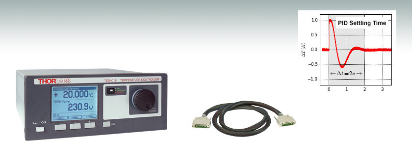
Fast Temperature Settling
by PID Controller
CAB4001
Different Connection Cables
Available as Accessory
TED4015


Please Wait
| Item # | TED4015 |
|---|---|
| Temperature Stability | 0.002 °C (24 hrs) |
| TEC Output | ±15 A |
| Compliance Voltage | 15 V |
| Temperature Control Range | -55 to 150 °C |
| Resistance Measurement Range (2 Ranges) |
100 Ω to 100 kΩ or 1kΩ to 1 MΩ |
| Temperature Resolution | 0.001 °C (0.1 Ω/1 Ω for Thermistors) |
Applications
- Precise Temperature Stabilization of Laser Diodes for Interferometry and Spectroscopy
- Control Temperature Set Point via External Input (Active Laser Wavelength Stabilization)
- Cooling of Detectors for Noise Reduction
- Temperature Stabilization of Nonlinear Crystals
- Temperature Stabilization of Industrial Systems
Features
- Excellent Temperature Stability: 0.002 °C (24 hrs)
- Digital PID Control with Separate P, I, and D Settings
- Automatic PID Setting Function
- Temperature Display in °C, °F, K
- Adjustable Temperature Sensor Offset
- Active Power Management for Efficient Power Use
- Compatible Sensors:
- NTC Thermistors
- Current Temperature Sensors
- Voltage Temperature Sensors
- Platinum RTD Temperature Sensors
- Control Modes:
- Constant Temperature
- Constant Current
- Enhanced Security Features:
- Adjustable TEC Current Limit
- Adjustable Temperature Limits
- Temperature Window Protection
- Sensor Fault Protection
- Interface and Drivers:
- USB Interface (SCPI Compliant)
- VXIpnp/VISA Drivers for Common Programming Environments like LabWindows/CVI™, LabVIEW™, and MS Visual Studio™
The TED4015 is a high-performance digital temperature controller designed to drive thermoelectric cooler (TEC) elements with currents up to ±15 A. It supports most common temperature sensors and can be adapted to different thermal loads. The TED4015 can be fully controlled via its robust, SCPI-compatible USB interface. The digital PID control offers an auto PID setting function or separate control of the P, I, and D parameters. The TED4015 boasts excellent temperature stability of 0.002 °C within 24 hrs, enhanced safeguard features, and error indicators, making this device ideal for cooling very sensitive devices where high stability, reliability, and precision is required. Thorlabs recommends recalibrating these spectrometers every 24 months and offers a factory recalibration service. To order this service, scroll to the bottom of the page and select Item # CAL-TED4.
Compared to our TED200C Temperature Controller, the TED4015 offers a wider TEC current range plus additional features like full digital control, easy auto PID setting, constant TEC current mode, set temperature protection, TEC voltage measurement, and adjustable temperature window protection. The TED4015 also offers silent operation.
For driver software, as well as programming reference guides for Standard Commands for the Programmable Instruments (SCPI) standard, LabVIEW™, Visual C++, Visual C#, and Visual Basic, please see the Software tab.
Adaptability to Different Thermal Loads
The TED4015 can easily be adapted to different thermal loads by a digital PID loop. The P (proportional) gain, the I (integral) offset control, and the D (derivative or differential) rates can be individually adjusted by the user or by the auto PID function. With optimum PID parameters, the settling time for a temperature change of 1 °C for a laser mounted in our LM14S2 Laser Diode Mount is less than 2 seconds.
Supported Temperature Sensors
The TED4015 temperature controller supports almost all common temperature sensors. A sensor selection in the Temperature Control Menu allows the use of thermistors up to 1000 kΩ, the use of a temperature sensing IC (such as the AD590) or the use of platinum RTD sensors. The temperature can be displayed in Celsius, Fahrenheit or Kelvin. For thermistors, two temperature calculation methods can be selected: Steinhart-Hart or exponential. The maximum control range is -55 to 150 °C, limited by the rated temperature range of the connected sensor and thermal setup.
Enhanced Security Features
The TED4015 is designed for maximum TEC element protection and stable as well as reliable operation. An adjustable TEC output current limit prevents the controller from overdriving the TEC element. This limit can be set from 0.1 A to the current range of the controller. Adjustable temperature limits and the temperature window protection provide alerts if the temperature of the TEC element exceed certain values.
The system indicates the presence of an incorrect or missing temperature sensor and a bad connection between sensor and controller by an LED on the TEC "On" key and an audible warning signal. The TEC current is automatically switched off if an error occurs.
Temperature Monitor Output
The TED4015 provides a monitoring signal proportional to the difference between actual and set temperature. An oscilloscope or an analog data acquisition card can be connected directly to the rear panel BNC connector to monitor the settling behavior with different thermal loads.
Companion Products
Our LDC200C Laser Diode Controllers are ideal companions for the TED4015. When combined with our TEC laser mounts, the TED4015 can achieve a thermal stability of 0.001 °C. This temperature stability is required for applications like laser diode wavelength tuning and atomic absorption cell spectroscopy.
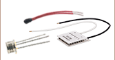
The TED4015 Ships with the Following Parts:
- Laser Mount Cable for TED4015: 5 A, 17W2, D-Sub-9 (Item Number CAB4000, Also Sold Below)
- DB-9 Connectors: 17W2, Male and Female, with Two High-Current 20 A Contacts (Item Number CON4001, Also Sold Below)
- USB Cable A-B, 2 m
- Driver CD
- Certificate of Calibration
- Operating Manual
| Item # | TED4015 | |
|---|---|---|
| Front Panela | Remote Controla | |
| TEC Current Output | ||
| Current Range | -15 A to +15 A | |
| Compliance Voltage | 15 V | |
| Maximum TEC Output Power | 225 W | |
| Setting Resolution (Constant Current Mode) | 1 mA | 0.1 mA |
| Accuracy | ±(0.2% + 20 mA) | |
| Ripple and Noise (10 Hz to 10 MHz, Typical) | <10 mA rms | |
| TEC Current Limit | ||
| Setting Range | 0.1 A to 15 A | |
| Setting Resolution | 1 mA | 0.1 mA |
| Accuracy | ±(0.2% + 10 mA) | |
| NTC Thermistor Sensors | ||
| Resistance Measurement Ranges | 100 Ω to 100 kΩ / 1 kΩ to 1 MΩ | |
| Control Range (Max)b | -55 to 150 °C | |
| Resolution (Temperature) | 0.001 °C | |
| Resolution (Resistance, 100 kΩ / 1 MΩ Range) | 0.1 Ω / 1 Ω | 0.03 Ω / 0.3 Ω |
| Accuracy (100 kΩ/1 MΩ Range)c | ±(0.06% + 1 Ω / 5 Ω) | |
| Temperature Stability 24 hours (Typical)b | <0.002 °C | |
| Temperture Coefficient | <5 mK/°C | |
| IC Sensors | ||
| Supported Current Temperature Sensors | AD590, AD592 | |
| Supported Voltage Temperature Sensors | LM335, LM235, LM135, LM35 | |
| Temperature Control Range with AD590 | -55 to 150 °C | |
| Temperature Control Range with AD592 | -25 to 105 °C | |
| Temperature Control Range with LM335 | -40 to 100 °C | |
| Temperature Control Range with LM235 | -40 to 125 °C | |
| Temperature Control Range with LM135 | -55 to 150 °C | |
| Temperature Control Range with LM35 | -55 to 150 °C | |
| Resolution | 0.001 °C | 0.0001 °C |
| Accuracy AD590 Current | ±(0.04% + 0.08 µA) | |
| Accuracy LM335/LM35 Voltage | ±(0.03% + 1.5 mV) | |
| Temperature Stability 24 hours | <0.002 °C | |
| Temperature Coefficient | <5 mK/°C | |
| Pt100/Pt1000 RTD Sensors | ||
| Temperature Control Range | -55 to 150 °C | |
| Resolution | 0.001 °C | 0.0003 °C |
| Accuracy | ±0.3 °C | |
| Temperature Stability (24 Hours, Typical) | <0.005 °C | |
| Temperture Coefficient | <20 mK/°C | |
| Temperature Window Protection | ||
| Setting Range Twin | 0.01 to 100.0 °C | |
| Protection Reset Delay | 0 to 600 s | |
| Window Protection Output | BNC, TTL 5V (Open Collector with Internal 2 kΩ Pull-Up Resistor) |
|
| Temperature Control Output | ||
| Load Resistance | >10 kΩ | |
| Transmission Coefficient | ΔT x 5 V / Twin ± 0.2 % (Temperature Deviation, Scaled to Temperature Window) |
|
| TEC Voltage Measurement | ||
| Measurement Principle | 4-Wire / 2-Wire | |
| Measurement Range | -16.5 V to +16.5 V | |
| Resolution | 100 mV | 40 mV |
| Accuracy (with 4-wire Measurement) | ±50 mV | |
| Digital I/O Port | ||
| Number of I/O Lines | 4 (Separately Configurable) | |
| Input Level | TTL or CMOS, Voltage Tolerant up to 24 V | |
| Output Level (Source Operation) | TTL or 5 V CMOS, 2 mA Max | |
| Output Level (Sink Operation) | Open Collector, Up to 24 V, 400 mA Max | |
| Interface | ||
| USB 2.0 | According USBTMC/USBTMC-USB488 Specification Rev. 1.0 | |
| Protocol | SCPI-Compliant Command Set | |
| Drivers | VISA VXIpnp™, MS Visual Studio™, MS Visual Studio.net™, NI LabView™, NI Labwindows/CVI™ | |
| General Data | ||
| Safety Features | TEC Current Limit, Sensor Fault Protection, Short Circuit when TEC Off, TEC Open Circuit Protection, Temperature Setpoint Limit, Temperature Window Protection, Over Temperature Protection, Keylock Switch |
|
| Display | LCD 320 x 240 pixels | |
| Connector for Sensor, TE Cooler, TEC On Signal | 17W2 Mixed D-sub Jack (Female) | |
| Connectors for Deviation Out and Temp Ok Out | BNC | |
| Connector for Digital I/O | Mini DIN 6 | |
| Connector for USB Interface | USB Type B | |
| Chassis Ground Connector | 4 mm Banana Jack | |
| Line Voltage / Frequency | 100 to120 V and 200 to 240 V ± 10% / 50 to 60 Hz ± 5% | |
| Maximum Power Consumption | 600 VA | |
| Mains Supply Overvoltage | Category II (Cat II) | |
| Operating Temperature (Non Condensing) | 0 to 40 °C | |
| Storage Temperature | -40 to 70 °C | |
| Relative Humidity | 80% Up to 31 °C Max, Decreasing to 50% at 40 °C | |
| Pollution Degree (Indoor Use Only) | 2 | |
| Operation Altitude | <2000 m | |
| Warm-Up Time for Rated Accuracy | 30 min | |
| Weight | 5.3 kg | |
| Dimensions (W x H x D) w/o Operating Elements | 263 mm x 122 mm x 307 mm | |
| Dimensions (W x H x D) with Operating Elements | 263 mm x 122 mm x 345 mm | |
All technical data valid at 23 ± 5 °C and 45 ± 15% relative humidity
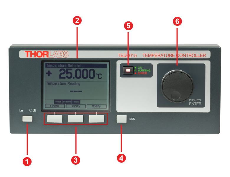
TED4015 Front Panel
| Callout | Connection | Callout | Connection |
|---|---|---|---|
| 1 | Supply Power Switch | 4 | Escape Key |
| 2 | LC Display | 5 | TEC Status Indicator |
| 3 | Softkeys for Menu Navigation | 6 | Adjustment Knob |
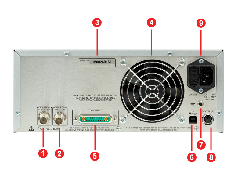
TED4015 Back Panel
| Callout | Connection | Callout | Connection |
|---|---|---|---|
| 1 | Actual Temperature Deviation Output "Deviation Out" -5 to 5 V | 6 | USB Connector |
| 2 | TTL Temperature Monitor Output "Temp OK Out" 5 V |
7 | 4 mm Banana Jack for Chassis Ground |
| 3 | Serial Number of the Unit | 8 | MiniDin-6 Jack "Digital I/O" |
| 4 | Cooling Fan | ||
| 5 | TEC Element Output and Temperature Sensor Input "TEC Output" | 9 | Power Connector and Fuse Holder "Line In" |
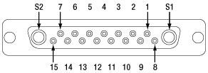
TEC Output
17W2 Mixed D-Sub Jack
| Pin | Connection | Pin | Connection |
|---|---|---|---|
| 1 | Interlock, TEC ON LED (+) | 10 | PT100/1000 (-), AD590/592 (-), LM35 Out, LM135/235/335 (+) |
| 2 | Voltage Measurement TEC Element (+) | 11 | PT100/1000 (+), AD590/592 (+), LM35/135/235/335 (+) |
| 3 | Thermistor (-), PT100/1000 (-), Analog Ground | 12 | Analog Ground, LM35/135/235/335 (-) |
| 4 | Thermistor (+), PT100/1000 (+) | 13 | Not Connected |
| 5 | Analog Ground, LM35/135/235/335 (-) | 14 | I/O 1-wire (Currently Not Used) |
| 6 | Digital Ground for I/O 1-Wire | 15 | Ground for 12 V Output and Interlock, TEC ON LED (-) |
| 7 | 12 V Output (for External Fan, Max Current = 500 mA) | S1 | TEC Element (+) (Peltier Element) |
| 8 | Not Connected | S2 | TEC Element (-)(Peltier Element) |
| 9 | Voltage Measurement TEC Element (-) |
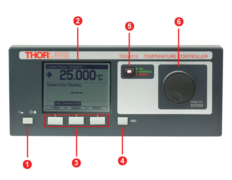
Digital I/O Ports
| Pin | Connection |
|---|---|
| 1 | I/O 1 |
| 2 | I/O 2 |
| 3 | I/O 3 |
| 4 | I/O 4 |
| 5 | GND |
| 6 | I/O Supply Voltage (+12 V from Internal or Higher External Voltage up to +24 V) |
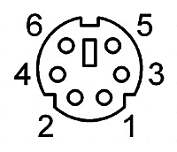
Deviation Out
BNC Female
Actual Temperature Deviation Output, -5 to +5 V
Temp OK Out
BNC Female
Temperature OK Output (High if Inside Temperature Window), TTL 5 V
Computer Connection
USB Type B
USB Type B to Type A Cable Included
Ground

4 mm Banana Jack for Chassis Ground
CAB4000 TEC Element Cable
This cable contains a DB-9 female connector on one side and a 17W2 male connector on the other side. Both views shown below are looking into the connector.
DB-9 Female Connector
17W2 Male Connector
| Pin Matching | |
|---|---|
| DB-9 Pin | 17W2 Pin(s) |
| 1 | 1, 15 |
| 2 | 4 |
| 3 | 3 |
| 4 | 2, S1 |
| 5 | 9, S2 |
| 6 | No Connection |
| 7 | 10 |
| 8 | 5, 12 |
| 9 | 11 |
| Shield | Shield |
| DB-9 Connector Colors | |
|---|---|
| Pin | Color |
| 1 | White |
| 2 | Pink and Gray |
| 3 | Red and Blue |
| 4 | Pink / Red / Purple (3 Wires) |
| 5 | Black / Gray / Blue (3 Wires) |
| 6 | No Connection |
| 7 | Yellow |
| 8 | Brown |
| 9 | Green |
| 17W2 Connector Colors | |||
|---|---|---|---|
| Pin | Color | Pin | Color |
| 1 | White | 10 | Yellow |
| 2 | Red | 11 | Green |
| 3 | Red and Blue | 12 | Brown |
| 4 | Pink and Gray | 13 | No Connection |
| 5 | Brown | 14 | No Connection |
| 6 | No Connection | 15 | White |
| 7 | No Connection | S1 | Purple / Pink (2 Wires) |
| 8 | No Connection | ||
| 9 | Blue | S2 | Black / Gray (2 Wires) |
Sample Screens of the TED4000
| Measurement Screen | Menu Screen | ||
|---|---|---|---|
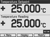 |
The top of this screen shows the Temperature Setpoint: temperature in Constant Temperature Mode and current in Constant Current Mode. At the bottom the actual measured value is shown. The units depend on the attached sensor. Peltier Current, Peltier Voltage and Peltier Power can be shown as well. A status line shows warnings and error-messages. | 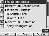 |
The menu screen allows selecting different operation modes and options. |
| Temperature Controller Screen | Temperature Mode Settings Screen | ||
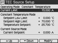 |
Via the Temperature Controller Screen all parameters for the temperature controller are entered: Operation Mode, Current Limit, Current Control Mode Settings, Temperature Sensor Settings. | 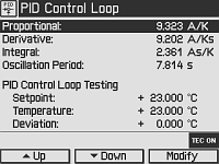 |
This Screen offers access to the PID and Temperature Limit Settings. |
| PID Auto-Tune Screen | Preference Screen | ||
 |
Via this Screen the PID auto parameter function is started. The TED4000 selects optimal PID parameters for the current settings. | 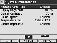 |
This Screen offers access to the device preferences, i.e. operation and display modes. |
Software for Laser Diode Controllers
The download button below links to VISA VXI pnp™, MS Visual Studio™, MS Visual Studio.net™, LabVIEW™, and LabWindows/CVI™ drivers, firmware, utilities, and support documentation for Thorlabs' ITC4000 Series laser controllers, LDC4000 Series laser controllers, CLD1000 Series compact laser diode controllers, and TED4000 Series TEC controllers.
The software download page also offers programming reference notes for interfacing with compatible controllers using SCPI, LabVIEW, Visual C++, Visual C#, and Visual Basic. Please see the Programming Reference tab on the software download page for more information and download links.
Driver Software
Version 3.1.0 (April 11, 2014)
Programming Reference
Version 3.3 (April 8, 2015) - SCPI Commands
Version 1.0 (June 16, 2015) - LabVIEW, Visual C++, Visual C#, Visual Basic
The software packages support LabVIEW 8.5 and higher. If you are using an earlier version of LabVIEW, please contact Technical Support for assistance.
The TED4015 ships with the following components:
| TED4015 | Component |
|---|---|
| x | Benchtop Temperature Controller, ±15 A/225 W (TED4015) |
| x | Cable TED4000 to laser mount, 5 A, 17W2, D-Sub-9 (CAB4000) |
| x | USB Cable A-B, 2 m |
| x | Operation Manual TED4015 |
| x | Distribution CD 4000 Series |
| x | Mixed D-Sub connector 17W2, male & female with 2 high current contacts each, 20 A (CON4001) |
PID Basics
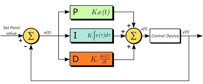
The PID circuit is often utilized as a control loop feedback controller and is commonly used for many forms of servo circuits. The letters making up the acronym PID correspond to Proportional (P), Integral (I), and Derivative (D), which represents the three control settings of a PID circuit. The purpose of any servo circuit is to hold the system at a predetermined value (set point) for long periods of time. The PID circuit actively controls the system so as to hold it at the set point by generating an error signal that is essentially the difference between the set point and the current value. The three controls relate to the time-dependent error signal. At its simplest, this can be thought of as follows: Proportional is dependent upon the present error, Integral is dependent upon the accumulation of past error, and Derivative is the prediction of future error. The results of each of the controls are then fed into a weighted sum, which then adjusts the output of the circuit, u(t). This output is fed into a control device, its value is fed back into the circuit, and the process is allowed to actively stabilize the circuit’s output to reach and hold at the set point value. The block diagram below illustrates the action of a PID circuit. One or more of the controls can be utilized in any servo circuit depending on system demand and requirement (i.e., P, I, PI, PD, or PID).
Through proper setting of the controls in a PID circuit, relatively quick response with minimal overshoot (passing the set point value) and ringing (oscillation about the set point value) can be achieved. Let’s take as an example a temperature servo, such as that for temperature stabilization of a laser diode. The PID circuit will ultimately servo the current to a Thermoelectric Cooler (TEC) (often times through control of the gate voltage on an FET). Under this example, the current is referred to as the Manipulated Variable (MV). A thermistor is used to monitor the temperature of the laser diode, and the voltage over the thermistor is used as the Process Variable (PV). The Set Point (SP) voltage is set to correspond to the desired temperature. The error signal, e(t), is then the difference between the SP and PV. A PID controller will generate the error signal and then change the MV to reach the desired result. For example, if e(t) states that the laser diode is too hot, the circuit will allow more current to flow through the TEC (proportional control). Since proportional control is proportional to e(t), it may not cool the laser diode quickly enough. In that event, the circuit will further increase the amount of current through the TEC (integral control) by looking at the previous errors and adjusting the output to reach the desired value. As the SP is reached (e(t) approaches zero), the circuit will decrease the current through the TEC in anticipation of reaching the SP (derivative control).
Please note that a PID circuit will not guarantee optimal control. Improper setting of the PID controls can cause the circuit to oscillate significantly and lead to instability in control. It is up to the user to properly adjust the PID gains to ensure proper performance.
PID Theory
The output of the PID control circuit, u(t), is given as
where
Kp= Proportional Gain
Ki = Integral Gain
Kd = Derivative Gain
e(t) = SP - PV(t)
From here we can define the control units through their mathematical definition and discuss each in a little more detail. Proportional control is proportional to the error signal; as such, it is a direct response to the error signal generated by the circuit:
Larger proportional gain results in larger changes in response to the error, and thus affects the speed at which the controller can respond to changes in the system. While a high proportional gain can cause a circuit to respond swiftly, too high a value can cause oscillations about the SP value. Too low a value and the circuit cannot efficiently respond to changes in the system.
Integral control goes a step further than proportional gain, as it is proportional to not just the magnitude of the error signal but also the duration of the error.
Integral control is highly effective at increasing the response time of a circuit along with eliminating the steady-state error associated with purely proportional control. In essence integral control sums over the previous error, which was not corrected, and then multiplies that error by Ki to produce the integral response. Thus, for even small sustained error, a large aggregated integral response can be realized. However, due to the fast response of integral control, high gain values can cause significant overshoot of the SP value and lead to oscillation and instability. Too low, and the circuit will be significantly slower in responding to changes in the system.
Derivative control attempts to reduce the overshoot and ringing potential from proportional and integral control. It determines how quickly the circuit is changing over time (by looking at the derivative of the error signal) and multiplies it by Kd to produce the derivative response.
Unlike proportional and integral control, derivative control will slow the response of the circuit. In doing so, it is able to partially compensate for the overshoot as well as damp out any oscillations caused by integral and proportional control. High gain values cause the circuit to respond very slowly and can leave one susceptible to noise and high frequency oscillation (as the circuit becomes too slow to respond quickly). Too low and the circuit is prone to overshooting the SP value. However, in some cases overshooting the SP value by any significant amount must be avoided and thus a higher derivative gain (along with lower proportional gain) can be used. The chart below explains the effects of increasing the gain of any one of the parameters independently.
| Parameter Increased | Rise Time | Overshoot | Settling Time | Steady-State Error | Stability |
|---|---|---|---|---|---|
| Kp | Decrease | Increase | Small Change | Decrease | Degrade |
| Ki | Decrease | Increase | Increase | Decrease Significantly | Degrade |
| Kd | Minor Decrease | Minor Decrease | Minor Decrease | No Effect | Improve (for small Kd) |
Tuning
In general the gains of P, I, and D will need to be adjusted by the user in order to best servo the system. While there is not a static set of rules for what the values should be for any specific system, following the general procedures should help in tuning a circuit to match one’s system and environment. A PID circuit will typically overshoot the SP value slightly and then quickly damp out to reach the SP value.
Manual tuning of the gain settings is the simplest method for setting the PID controls. However, this procedure is done actively (the PID controller turned on and properly attached to the system) and requires some amount of experience to fully integrate. To tune your PID controller manually, first the integral and derivative gains are set to zero. Increase the proportional gain until you observe oscillation in the output. Your proportional gain should then be set to roughly half this value. After the proportional gain is set, increase the integral gain until any offset is corrected for on a time scale appropriate for your system. If you increase this gain too much, you will observe significant overshoot of the SP value and instability in the circuit. Once the integral gain is set, the derivative gain can then be increased. Derivative gain will reduce overshoot and damp the system quickly to the SP value. If you increase the derivative gain too much, you will see large overshoot (due to the circuit being too slow to respond). By playing with the gain settings, you can maximize the performance of your PID circuit, resulting in a circuit that quickly responds to changes in the system and effectively damps out oscillation about the SP value.
| Control Type | Kp | Ki | Kd |
|---|---|---|---|
| P | 0.50 Ku | - | - |
| PI | 0.45 Ku | 1.2 Kp/Pu | - |
| PID | 0.60 Ku | 2 Kp/Pu | KpPu/8 |
While manual tuning can be very effective at setting a PID circuit for your specific system, it does require some amount of experience and understanding of PID circuits and response. The Ziegler-Nichols method for PID tuning offers a bit more structured guide to setting PID values. Again, you’ll want to set the integral and derivative gain to zero. Increase the proportional gain until the circuit starts to oscillate. We will call this gain level Ku. The oscillation will have a period of Pu. Gains for various control circuits are then given to the right in the chart.
Note that when using the Ziegler-Nichols tuning method with some devices like the DSC1 digital servo controller, the integral and derivative terms must be normalized by the sample rate. To do this, the integral term determined from the table should be divided by the sample rate in Hertz and the derivative term should be multiplied by the sample rate in Hertz.
| Posted Comments: | |
David H
(posted 2024-09-03 12:47:01.933) I'm using TED4015 with TH10K.
In "Temperature Sensor Setup" menu I can choose Exponential or Steinhart-Hart.
I can't use Exponential because TH10K doesn't include that info in the datasheet. So I try to use Steinhart-Hart. From the TH10K datasheet I get A=3.3530481E-03, B=2.5420230E-04, C=-6.9383563E-08 (Note that based on the wikipedia definition, "d" in the datasheet is actually C in the steinhart-hart equation, so I'm using the datasheet's "d" here as the TED4015's "C".)
OK now there are two problems. First, TED4015 doesn't accept a negative number. Second, if I use the TH10K's positive "c" (1.1431163E-06) instead of "d", then it is greater than unity, and TED4015 doesn't accept a value greater than 1.0E-6.
So, what A,B,C (or R0, T0, beta) values do I use for TH10K? hkarpenko
(posted 2024-09-05 04:16:14.0) Dear David,
thank you for your feedback.
The A,B,C and D values in the datasheet of the thermistor TH10K are given for a relative resistance. Thus these cannot be used for the settings in the TED4015 driver. Therefore you can use the table below "R-T curve selection", from which you can derive the needed parameters A,B and C. The parameters I got from this table are
A = 1.111156282e-3
B = 2.372849520e-4
C = 7.357486264e-8
I will contact you directly to assisst you on this. Fasih Zareef
(posted 2024-07-30 13:03:52.29) Hello,
I am interested in this product for laboratory measurements. Our desired temperatures are in the range of -25 to +30C. I wanted to know what inputs are required by TEC to maintain this temperature e.g. chiller temperature, coolant, sensors, etc. hkarpenko
(posted 2024-07-31 09:06:09.0) Dear Fasih,
thank you for your feedback.
To reach the desired temperature on your sample it is important to select the suitable TEC element and design the heatsink accordingly. I will contact you directly to discuss this issue further with you. Iko Ben-Giat
(posted 2024-06-06 21:29:08.61) Hello
We are using TED4015 Temp. controller, and we have encountered a problem, when connected to USB (for remote), temp. fluctuate +/- 0.005 degrees, while without USB fluctuations are +/- 0.001 degrees as in the specs.
We added some ferrites on the USB cable which reduce the frequency of the fluctuations, but still their amplitude was +/- 0.005 degrees.
Please advise
Iko Ben Giat - Chief Product and Engineering
Iko@tera.group hkarpenko
(posted 2024-06-07 11:01:24.0) Dear customer,
thank you for your feedback. It can have several reasons why it is the case. I will contact you directly to discuss this issue with you. ZENG Yanquan
(posted 2024-03-26 15:56:23.087) May I ask that is it multichannel? I need to controll 4 TECs instantaneously, maybe with the same power. dmehmedov
(posted 2024-03-26 12:00:12.0) Dear Zeng Yanquan,
thank you for your feedback. The controller is single channel, and you would not be able to control all four TEC elements since you have only one temperature input.
I will contact you directly to provide further information. Matteo Buffolo
(posted 2023-08-03 15:44:35.18) Hi, I would like to know whether the output current/power is controlled via switching or linear regulation. Thanks. dpossin
(posted 2023-08-04 07:10:20.0) Dear Matteo,
Thank you for your feedback. The temperature controller use an closed loop feedback system via an PID feedback control which adjusts the input current level and polarity. Steve Erisman
(posted 2023-07-06 08:29:19.117) Good morning. Will the 225 W TEC Controller drive 2 Kapton Heaters in parallel with a total resistance of 40ohm?
These are 12v heaters, actual current 0.15amp / Max 3amp. It is using a 1k ohm Platinum RTD. hkarpenko
(posted 2023-07-12 02:31:10.0) Dear Steve,
thank you for your feedback. The heater TED4015 is suitable for your application. In the worst case, the power is not distributed equally if the internal resistance of both heaters is not the same or changes unequally with the heating. Joe Williams
(posted 2021-06-25 19:56:16.433) What is the current from pins 3 and 4 when using a PT1000 RTD as the temperature sensor? MKiess
(posted 2021-07-09 10:55:24.0) Dear Joe, thank you very much for your inquiry. The measuring current when using a PT1000 RTD is 50 µA. Douglas Kuik
(posted 2021-04-14 14:19:37.817) Can you provide me with a calibration adjustment procedure for the TED4015? wskopalik
(posted 2021-04-16 03:48:28.0) Thank you very much for your feedback!
I will send you a document which describes the calibration procedure on the TED4015 devices. We also offer a calibration service for these devices, if you are interested in that.
I will contact you directly to provide further information. Mike Pivnenko
(posted 2020-07-07 15:22:37.233) Hi.
I have just received the controller and work with it for a few hours. Seems to work OK. I use it with TECH4 and AD590. A couple of questions.
1. The fun inside the unit does not rotate. Is it OK?
2. It continuously makes repetitive noise, like double click with about 53-54 double clicks per minute. Is it normal?
Thank you,
Mike MKiess
(posted 2020-07-08 07:59:43.0) This is an response from Michael of Thorlabs. Thank you very much for your inquiry. I have contacted you directly to discuss your application, configuration and related features in more detail. betrand
(posted 2018-03-12 03:00:59.23) Hi,my question is as following. Could the TED4015 be used to drive heaters instead of TEC elements? If it is possible, please let me know the setup and the necessary information.
Bertrand swick
(posted 2018-03-15 05:12:39.0) This is a response from Sebastian at Thorlabs. Thank you for the inquiry. Without additional circuitry it is not possible to drive heaters with TED4015. The temperature regulation is designed for active heating and cooling by driving peltier elements. I contacted you directly to discuss alternative solutions. swick
(posted 2018-03-19 06:14:01.0) This is a response from Sebastian at Thorlabs. Thank you for the inquiry. With TED4015 it is not possible to drive heaters without additional circuitry. The temperature regulation is designed for active heating and cooling by driving peltier elements. I contacted you directly to discuss alternative solutions. andreas.daetwyler
(posted 2017-03-29 10:07:24.463) Hi
Do you have a rack mount kit 19" for the part TED 4015?
Thank you
Regards
Andreas swick
(posted 2017-04-03 03:16:56.0) This is a response from Sebastian at Thorlabs. Thank you very much for your feedback.
At the time we do not offer a mounting kit for TED4015 compatible to 19'' racks. We will internally discuss this idea. cpepe
(posted 2017-02-20 06:03:45.68) Hi, I am looking for a temperature controller for a temperature sensor of the Cernox RTDs type. I was wondering if your 225 W TEC Controller will work with this type of sensor? Will it be able to measure temperature at 1.5 K ? wskopalik
(posted 2017-02-21 03:09:17.0) This is a response from Wolfgang at Thorlabs. Thank you very much for your inquiry.
We would need to check the exact specifications of this sensor for a definite answer. With the NTC thermistors Thorlabs offers, the control range goes down to -55°C. For other sensors this range would change due to the different relation between resistance and temperature.
I have contacted you directly so we can have a look at the sensor specifications in more detail. kwestla
(posted 2016-12-16 10:19:39.863) Can the TED4015 also be used to drive patch style heaters as long as the current limit is set appropriately? tfrisch
(posted 2016-12-20 09:42:09.0) Hello, thank you for contacting Thorlabs. I will reach out to you directly about the details of your heater. melihc10
(posted 2016-11-14 13:36:05.64) Hi there, i wanna learn output waveform of this device. We are trying to drive heater with 100kHz pulses. This one seems like a DC current, isn't it? swick
(posted 2016-11-15 04:28:14.0) This is a response from Sebastian at Thorlabs. Thank you very much for your inquiry.
The TED4015 is not designed to provide modulated electrical current with high frequencies. The typical timing of the PID regulation is around 0.1 to 10 seconds.
Using the USB interface in constant current mode for applying set points (0 A and e.g. 15 A) would lead to max. frequency of 100 Hz. tschalk
(posted 2013-10-16 07:32:00.0) This is a response from Thomas at Thorlabs. Thank you very much for your inquiry. Unfortunately there is no way to mount the TED4015 into a 19" rack. The only devices which are compatible with a 19" rack are the PRO8000 Series (https://www.thorlabs.com/newgrouppage9.cfm?objectgroup_id=895&pn=PRO8000#1649) or the TXP Series (https://www.thorlabs.de/newgrouppage9.cfm?objectgroup_id=924). hadi.abidin
(posted 2013-10-15 07:54:00.017) Hallo
Is there a way to mount the TED4015 securely onto a 19' rack? |
| Item # | CAB4000 | CAB4001 | CON4001 |
|---|---|---|---|
| Click Image to Enlarge | 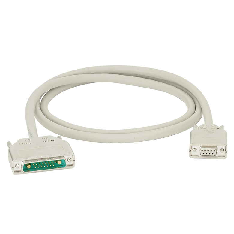 |
 |
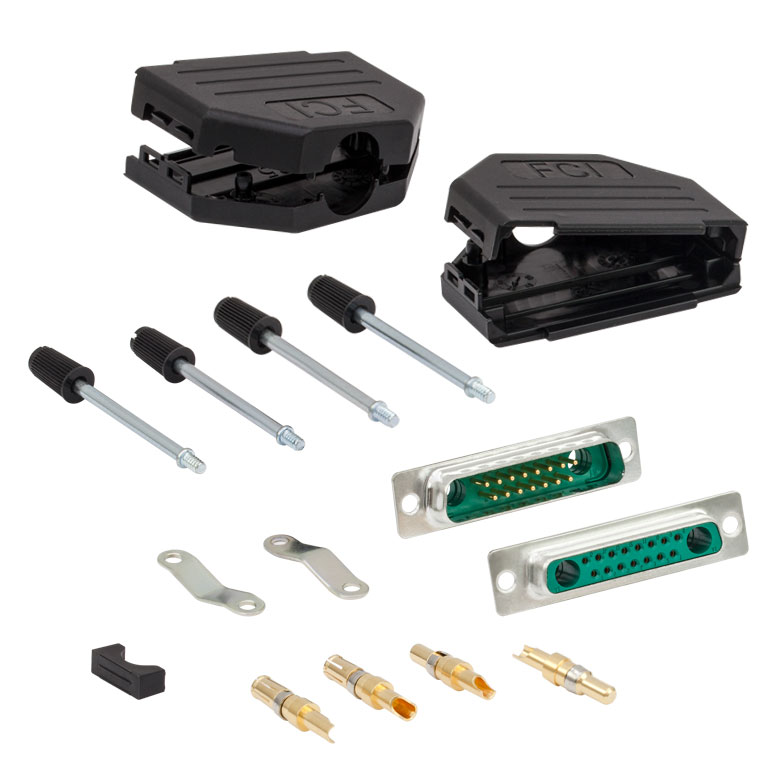 |
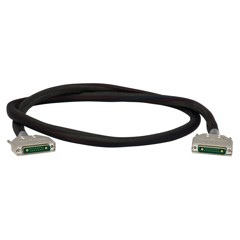
| Description | Standard TEC Element Cable | High Current TEC Element Cable | 17W2 Male and Female Connector Kit (One Each) |
| Max Current | 5 A | 20 A | 20 A |
| Connector Type | 17W2 Male to DB-9 Female | 17W2 Male to 17W2 Male | Loose 17W2 Connectors, Male and Female |
These cables connect our TED4015 temperature controller or our ITC4000 series dual current / temperature controllers to thermoelectric cooling elements. We also provide loose 17W2 connectors for customers who wish to make their own cables. Please see the Pin Diagrams tab for specific pinout information.
Please note that one CAB4000 cable and one CON4001 connector set are included with the purchase of a TED4015 benchtop controller.
Thorlabs offers a recalibration service for our TED4015 Temperature Controller. To ensure accurate measurements, we recommend recalibrating the devices every 24 months.
Requesting a Calibration
Thorlabs provides two options for requesting a calibration:
- Complete the Returns Material Authorization (RMA) form. When completing the RMA form, please enter your name, contact information, the Part #, and the Serial # of the item being returned for calibration; in the Reason for Return field, select "I would like an item to be calibrated." All other fields are optional. Once the form has been submitted, a member of our RMA team will reach out to provide an RMA Number, return instructions, and to verify billing and payment information.
- Enter the Part # and Serial # of the item that requires recalbration below and then Add to Cart. A member of our RMA team will reach out to coordinate return of the item for calibration. Should you have other items in your cart, note that the calibration request will be split off from your order for RMA processing.
Please Note: To ensure your item being returned for calibration is routed appropriately once it arrives at our facility, please do not ship it prior to being provided an RMA Number and return instructions by a member of our team.