 Products Home / Optical Elements / Optical Lenses / Aspheric Lenses: Molded & Precision Polished / Molded Aspheric Lenses / Molded Glass Aspheric Lenses: 350 - 700 nm AR Coating
Molded Glass Aspheric Lenses: 350 - 700 nm AR Coating
- High NA (0.15 to 0.7)
- Diffraction-Limited Design
- Broadband AR-Coated for 350 - 700 nm
- Collimate or Focus Light with a Single Element
A375TM-A
A375-A
C140TMD-A
354140-A
C710TMD-A
354710-A
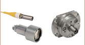
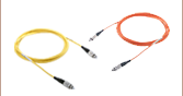
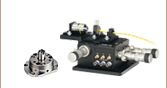
Application Idea
Aspheric Lens in a Fiber Launch Application


Please Wait
| Table 1.1 Molded Glass Aspheric Lenses |
|---|
| Infinite Conjugate |
| Uncoated |
| 350 - 700 nm (-A Coating) |
| 600 - 1050 nm (-B Coating) |
| 1050 - 1700 nm (-C Coating) |
| 1.8 - 3 µm (-D Coating) |
| 3 - 5 µm (-E Coating) |
| 8 - 12 µm (-F Coating) |
| 405 nm V-Coating |
| 1064 nm V-Coating |
| Finite Conjugate |
| Uncoated |
| Webpage Features | |
|---|---|
| |
Click for complete specifications. |
| Performance Hyperlink | Click to view item-specific focal length shift data and spot diagrams at various wavelengths. |
 Zemax Files Zemax Files |
|---|
| Click on the red Document icon next to the item numbers below to access the Zemax file download. Our entire Zemax Catalog is also available. |
Features
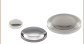
- Molded Glass Aspheric Lenses Designed for Infinite Magnification
- Focus or Collimate Light Without Introducing Spherical Aberration
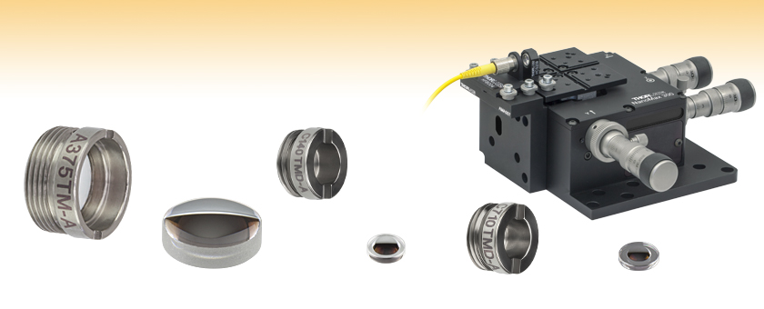
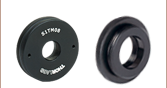
- Available Unmounted or Pre-Mounted in Non-Magnetic 303 Stainless Steel Lens Cells
Engraved with the Item # - Broadband AR Coating for 350 - 700 nm
Aspheric lenses focus or collimate light without introducing spherical aberration into the transmitted wavefront. For monochromatic sources, spherical aberration often prevents a single spherical lens from achieving diffraction-limited performance when focusing or collimating light. Aspheric lenses are designed to mitigate the impacts of spherical aberration and are often the best single element solution for many applications including collimating the output of a fiber or laser diode, coupling light into a fiber, spatial filtering, or imaging light onto a detector.
All of the molded glass lenses featured on this page are available with an antireflection coating for the 350 - 700 nm range deposited on both sides. Other AR coating options are listed in Table 1.1.
These lenses can be purchased unmounted or premounted in non-magnetic 303 stainless steel lens cells that are engraved with the Item # for easy identification. All mounted aspheres have a metric thread that makes them easy to integrate into an optical setup or OEM application; they can also be readily used with our SM1-threaded (1.035"-40) lens tubes by using our aspheric lens adapters. When combined with our microscope objective adapter extension tube, mounted aspheres can be used as a drop-in replacement for multi-element microscope objectives.
A selection of the lenses sold on this page are designed for collimating laser diodes. As seen in the tables below, a compatible laser window thickness is listed for these lenses. In these instances, the numerical aperture (NA), working distance (WD), and wavefront error of these lenses are defined based on the presence of a laser window of the indicated thickness (not included).
If an unmounted aspheric lens is being used to collimate the light from a point source or laser diode, the side with the greater radius of curvature (i.e., the flatter surface) should face the point source or laser diode. To collimate light using one of our mounted aspheric lenses, orient the housing so that the externally threaded end of the mount faces the source.
Molded glass aspheres are manufactured from a variety of optical glasses to yield the indicated performance. The molding process will cause the properties of the glass (e.g., Abbe number) to deviate slightly from those given by glass manufacturers. Specific material properties for each lens can be found by clicking on the Info Icon ![]() in the tables below and selecting the Glass tab.
in the tables below and selecting the Glass tab.
Choosing a Lens
Aspheric lenses are commonly chosen to couple incident light with a diameter of 1 - 5 mm into a single mode fiber. A simple example will illustrate the key specifications to consider when trying to choose the correct lens.
Example:
Fiber: P1-630A-FC-2
Collimated Beam Diameter Prior to Lens: Ø3 mm
The specifications for the P1-630A-FC-2, 630 nm, FC/PC single mode patch cable indicate that the mode field diameter (MFD) is 4.3 μm. This specification should be matched to the diffraction-limited spot size given by the following equation:
![]()
Here, f is the focal length of the lens, λ is the wavelength of the input light, and D is the diameter of collimated beam incident on the lens. Solving for the desired focal length of the collimating lens yields
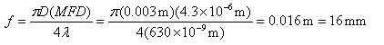
Thorlabs offers a large selection of mounted and unmounted aspheric lenses to choose from. The aspheric lens with a focal length that is closest to 16 mm has a focal length of 15.29 mm (Item # 354260-B or A260-B). This lens also has a clear aperture that is larger than the collimated beam diameter. Therefore, this option is the best choice given the initial parameters (i.e., a P1-630A-FC-2 single mode fiber and a collimated beam diameter of 3 mm). Remember, for optimal coupling, the spot size of the focused beam must be less than the MFD of the single mode fiber. As a result, if an aspheric lens is not available that provides an exact match, then choose one with a focal length that is shorter than the calculation above yields. Alternatively, if the clear aperture of the aspheric lens is large enough, the beam can be expanded before the aspheric lens, which has the result of reducing the spot size of the focus beam.
Aspheric Lens Design Formula
| Definitions of Variables | |
|---|---|
| z | Sag (Surface Profile) as a Function of Y |
| Y | Radial Distance from Optical Axis |
| R | Radius of Curvature |
| k | Conic Constant |
| An | nth Order Aspheric Coefficient |
The aspheric surfaces of these lenses may be described using a polynomial expansion in Y, the radial distance from the optical axis. The surface profile or sagitta (often abbreviated as sag) is denoted by z, and is given by the following expression:
where R is the radius of curvature, k is the conic constant, and the An are the nth order aspheric coefficients. The sign of R is determined by whether the center of curvature for the lens surface is located to the right or left of the lens' vertex; a positive R indicates that the center of curvature is located to the right of the vertex, while a negative R indicates that the center of curvature is located to the left of the vertex. For example, the radius of curvature for the left surface of a biconvex lens would be specified as positive, while the radius of curvature for its right surface would be specified as negative.
Aspheric Lens Coefficients
Due to the rotational symmetry of the lens surface, only even powers of Y are contained in the polynomial expansion above. The target values of the aspheric coefficients for each product can be found by clicking either on the blue Info Icons in the tables below (![]() ) or on the red documents icon (
) or on the red documents icon ( ) next to each lens sold below.
Choosing a Collimation Lens for Your Laser Diode
Since the output of a laser diode is highly divergent, collimating optics are necessary. Aspheric lenses do not introduce spherical aberration and therefore are commonly chosen when the collimated laser beam is to be between one and five millimeters. A simple example will illustrate the key specifications to consider when choosing the correct lens for a given application. The second example below is an extension of the procedure, which will show how to circularize an elliptical beam.
Example 1: Collimating a Diverging Beam
- Laser Diode to be Used: L780P010
- Desired Collimated Beam Diameter: Ø3 mm (Major Axis)
When choosing a collimation lens, it is essential to know the divergence angle of the source being used and the desired output diameter. The specifications for the L780P010 laser diode indicate that the typical parallel and perpendicular FWHM beam divergences are 8° and 30°, respectively. Therefore, as the light diverges, an elliptical beam will result. To collect as much light as possible during the collimation process, consider the larger of these two divergence angles in any calculations (i.e., in this case, use 30°). If you wish to convert your elliptical beam into a round one, we suggest using an anamorphic prism pair, which magnifies one axis of your beam; for details, see Example 2 below.
Assuming that the thickness of the lens is small compared to the radius of curvature, the thin lens approximation can be used to determine the appropriate focal length for the asphere. Assuming a divergence angle of 30° (FWHM) and desired beam diameter of 3 mm:
 |
 |
||
| Θ = Divergence Angle | Ø = Beam Diameter | f = Focal Length | r = Collimated Beam Radius = Ø/2 |
Note that the focal length is generally not equal to the needed distance between the light source and the lens.
With this information known, it is now time to choose the appropriate collimating lens. Thorlabs offers a large selection of aspheric lenses. For this application, the ideal lens is a molded glass aspheric lens with focal length near 5.6 mm and our -B antireflection coating, which covers 780 nm. The C171TMD-B (mounted) or 354171-B (unmounted) aspheric lenses have a focal length of 6.20 mm, which will result in a collimated beam diameter (major axis) of 3.3 mm. Next, check to see if the numerical aperture (NA) of the diode is smaller than the NA of the lens:
0.30 = NALens > NADiode ≈ sin(15°) = 0.26
Up to this point, we have been using the full-width at half maximum (FWHM) beam diameter to characterize the beam. However, a better practice is to use the 1/e2 beam diameter. For a Gaussian beam profile, the 1/e2 diameter is almost equal to 1.7X the FWHM diameter. The 1/e2 beam diameter therefore captures more of the laser diode's output light (for greater power delivery) and minimizes far-field diffraction (by clipping less of the incident light).
A good rule of thumb is to pick a lens with an NA twice that of the laser diode NA. For example, either the A390-B or the A390TM-B could be used as these lenses each have an NA of 0.53, which is more than twice the approximate NA of our laser diode (0.26). These lenses each have a focal length of 4.6 mm, resulting in an approximate major beam diameter of 2.5 mm. In general, using a collimating lens with a short focal length will result in a small collimated beam diameter and a large beam divergence, while a lens with a large focal length will result in a large collimated beam diameter and a small divergence.
Example 2: Circularizing an Elliptical Beam
Using the laser diode and aspheric lens chosen above, we can use an anamorphic prism pair to convert our collimated, elliptical beam into a circular beam.
Whereas earlier we considered only the larger divergence angle, we now look at the smaller beam divergence of 8°. From this, and using the effective focal length of the A390-B aspheric lens chosen in Example 1, we can determine the length of the semi-minor axis of the elliptical beam after collimation:
r' = f * tan(Θ'/2) = 4.6 mm * tan(4°) = 0.32 mm
The minor beam diameter is double the semi-minor axis, or 0.64 mm. In order to magnify the minor diameter to be equal to the major diameter of 2.5 mm, we will need an anamorphic prism pair that yields a magnification of 3.9. Thorlabs offers both mounted and unmounted prism pairs. Mounted prism pairs provide the benefit of a stable housing to preserve alignment, while unmounted prism pairs can be positioned at any angle to achieve the exact desired magnification.
The PS883-B mounted prism pair provides a magnification of 4.0 for a 950 nm wavelength beam. Because shorter wavelengths undergo greater magnification when passing through the prism pair, we can expect our 780 nm beam to be magnified by slightly more than 4.0X. Thus, the beam will still maintain a small degree of ellipticity.
Alternatively, we can use the PS871-B unmounted prism pair to achieve the precise magnification of the minor diameter necessary to produce a circular beam. Using the data available here, we see that the PS871-B achieves a magnification of 4.0 when the prisms are positioned at the following angles for a 670 nm wavelength beam:
| α1: +34.608° | α2: -1.2455° |
Refer to the diagram to the right for α1 and α2 definitions. Our 780 nm laser will experience slightly less magnification than a 670 nm beam passing through the prisms at these angles. Some trial and error may be required to achieve the exact desired magnification. In general:
- To increase magnification, rotate the first prism clockwise (increasing α1) and rotate the second prism counterclockwise (decreasing α2).
- To reduce magnification, rotate the first prism counterclockwise (decreasing α1) and rotate the second prism clockwise (increasing α2).
| Posted Comments: | |
jdelia
(posted 2025-06-12 02:19:13.0) Thank you for reaching out. At the time of posting this response, the website accurately reflects the volume pricing for our 354340-A lenses. I have reached out to you directly via email to clarify the issue you found. Min Uk Jung
(posted 2025-01-21 10:30:08.87) Dear manager,
Hello! I'm the student who studying in Pusan National University.
Could you provide the meaning of the "Laser Window Thickness"?
I searched them in google but I can't find the more detail about it.
Thank you
MinUk Jung EGies
(posted 2025-01-22 01:16:39.0) Thank you for contacting Thorlabs. Some of these lenses have their numerical apertures (NA) and working distances (WD) defined based on the presence of a laser window. An example image showing this laser window positioning for the 355110-A lens can be found here: https://www.thorlabs.com/images/popupimages/110_Drawing_D1-450.gif. For the lenses whose NA and WD are defined based on this, the “Laser Window Thickness” refers to the expected window thickness at which these values were defined. I have reached out to you directly regarding this. ILIYA SHOFMAN
(posted 2024-10-01 14:38:54.16) I opened the ZEMAX file for the A375TM-A lens (7.5mm effective focal length, mounted lens). I noticed that the zemax model had a 0.275mm window of N-BK7 before the image plane. Why is this window included in the model?
I didn't notice an equivalent window in the actual lens (I purchased the A375-TM before). Thank you for your clarification! tdevkota
(posted 2024-10-02 04:20:56.0) Thank you for reaching out to Thorlabs. The lenses with an LTW (Laser Window Thickness) spec are designed for collimating TO can laser diodes, which usually have glass windows. Therefore, the Zemax models for these lenses are simulated with the window included, even though the lenses themselves do not have a window. While they can certainly be used without the window, they are optimized for this application; using them in other contexts may lead to aberrations. Iliya Shofman
(posted 2024-01-19 19:49:34.077) Hello,
I wanted to clarify the exact meaning of the "Working Distance" specification. Working distance is typically defined as the distance between the focal point and the front edge of the lens. Does this include the threaded lens mount (i.e., what if the lens is sunk inside the lens mount ring)?
Thank you kindly,
Iliya. jpolaris
(posted 2024-01-23 07:57:50.0) Thank you for contacting Thorlabs. The definition of working distance can vary somewhat from lens to lens. These definitions are typically given as notes below the specification tables. If you click the blue "i" icons in the specification table in the Info column, a pop-up window will appear with a reference drawing. Taking unmounted lens 354710-A and the mounted version C710TMD-A as examples, the mounted version has a 0.1 mm shorter working distance than the unmounted version. This is because, for the mounted version, the working distance is defined from the back of the mount, and the lens is recessed somewhat into the mount. For the unmounted version, the working distance is measured from the plano surface of the lens. In both cases, the measurement of working distance is taken up to the window of the laser diode you are collimating. I have reached out to you directly with more information and to discuss further. Kyle Arnold
(posted 2024-01-16 17:30:53.213) Can I check what is the material absorption for D-ZK3 glass at 350nm (eg. C453TMD-A)? It is right at the edge of the given plot and I can't tell if it is 90% or much lower.
Of the thorlabs lenses we have, the one with good transmission at 350nm is D-K59 glass, but only A220TM-A (11mm focal length) uses this glass. jdelia
(posted 2024-02-01 09:16:32.0) Thank you for contacting Thorlabs. I have reached out to you directly to share the raw data for our D-ZK3 transmission graph. Internal transmission at 350 nm should be between 90.3% and 90.9%. Sabine Wollmann
(posted 2022-05-30 11:38:48.273) Dear Thorlabs,
could you provide me data for the damage threshold of this lens please?
Many thanks
Sabine cdolbashian
(posted 2022-06-06 11:10:00.0) Thank you for reaching out to us Sabine. While we do not have full damage threshold data for all of our lenses, I can confirm that in your case, your laser with 100mW of power will be easily compatible with these lenses and coatings therein. Y BoH
(posted 2020-12-11 21:40:55.72) When you are facing many boxes full of random mounted molded aspheric in the lab, trying to find one for a fiber coupler, it would be super useful if the laser marking on the side of the lens is not just meaning less model number but also the focal length of the lens. YLohia
(posted 2020-12-24 11:16:13.0) Hello, thank you for your feedback. We are always looking to improve are existing products and will consider adding more useful engravings in the future. user
(posted 2020-09-08 20:35:54.0) There is a typo on note 8 of the "Auto CAD PDF" for C340TMD-A. The working distance reference points are not given. "from" is typed twice YLohia
(posted 2020-09-09 10:46:54.0) Hello, thank you for your feedback. We will correct this typo. Ibrahim Kucukkara
(posted 2020-08-25 04:03:45.893) I have a 9mm TO can type L450G1 450nm laser diode with beam diameter of 6mm. Will you please suggest me a collimating lens and a proper adaptor and lens tube for a good collimation?
Thank you very much for your valuable help in advance.
Regards
İbrahim YLohia
(posted 2020-08-25 04:12:05.0) Hello Ibrahim, thank you for contacting Thorlabs. Please see the Collimation Tutorial tab on this page for information on picking appropriate collimation lenses. I have reached out to you directly to discuss your application and requirements further. Gerald Auböck
(posted 2020-03-10 13:07:07.22) Dear Ladies and Gentleman,
do you have a damage threshold for your N414-A
(CW operation),
thanks and Best Regards,
Gerald nbayconich
(posted 2020-03-20 02:10:21.0) Thank you for contacting Thorlabs. At the moment we have not tested these optics for pulsed or CW damage threshold limitations. I will reach out to you directly to discuss your application. user
(posted 2019-04-01 14:34:42.947) The aspheric coefficients in Zemax file have the same sign:
-0.00015041
-2.451e-006
-0.00000002547
The aspheric coefficients shown in this page have different signs:
-0.00015041
-2.451e-006
-0.00000002547 YLohia
(posted 2019-04-04 09:02:11.0) Hello, thank you for contacting Thorlabs. The aspheric coefficients change sign based on the direction the lens is pointing. The coefficients are correct in Zemax as well as the info icon. All of these coefficients should have the same sign. That being said, we did find an issue with the signs on the product page of this lens (https://www.thorlabs.com/thorproduct.cfm?partnumber=A397-A) and are working to correct it. yusefzadib
(posted 2017-04-14 15:36:40.633) Hi
I used bellow products to setup a laser source:
1.C110TMD-A, f = 6.24 mm, NA = 0.40,
2.L638P700M, 638 nm, 700 mW, Ø5.6 mm,G Pin code
3.LDH56-P2/M, 30 mm Cage Plate Collimation Mount
4.SR9HF, ESD Protection and Strain Relief Cable, Pin Codes F and G, 7.5 V
However, I couldn't get a suitable collimated beam. It was
It should be mentioned that all focal distances were checked with precise devices. tfrisch
(posted 2017-04-28 09:46:34.0) Hello, thank you for contacting Thorlabs. I notice that your source is a multimode laser diode which is expected to have greater divergence at collimation than a similar single mode source. I will reach out to you directly about your application. richard
(posted 2017-02-16 13:08:52.723) Hello,
I was wondering if you could provide the concentricity tolerance between the mounted optic and the 9.24 mm OD of your M9 threaded mounted aspheres (such as A397TM-A). tfrisch
(posted 2017-03-01 05:00:18.0) Hello, thank you for contacting Thorlabs. Most units will be seated better than the absolute tolerances of the lens and bore diameters, but 0.19mm is the worst case scenario. chiwon.lee
(posted 2017-01-09 10:06:57.053) Hello, is it possible to manufature aspheric lenes with deep UV (250 nm) anti-reflective coating? tfrisch
(posted 2017-01-09 11:59:30.0) Hello, thank you for contacting Thorlabs. So far into the UV, absorption will be come a concern. I will reach out to you directly with information on materials that may be suitable for a UV range asphere. mbennahmias
(posted 2016-06-27 10:54:25.437) Hello,
I would like to know what is the laser induced damage threshold for this optical element / AR coating.
I am using a 0.2 W 375 nm laser diode and the diverging beam size at this location is ~ 0.1 to 0.2 mm andrew.logan
(posted 2014-12-16 13:52:10.44) In the drawings for the 354560-A you give the tolerance on the lens diameter at +/- 0.15 mm, whereas Lightpath's 2014 pdf catalogue shows their typical tolerance as +/- 0.015 mm. Is this a typo, or does the 354560 have a tolerance that is an order of magnitude worse than what is typical of Lightpath?
Thanks myanakas
(posted 2015-01-14 02:19:40.0) Response from Mike at Thorlabs: Thank you for your feedback. This is a typo, the correct tolerance is +/- 0.015. We are currently working to have the website updated to correct this. moritz.kick
(posted 2014-01-07 15:25:08.0) Hi,
we want to couple a laser beam into and out of a fiber. The wavelength is 580 nm, we use the 460-HP fiber (MFD 3.5µm) and the Collimated Beam Diameter prior to Lens is about 1.3 mm.
I calculated f as 6.16 so the best aspheric lens for coupling the light into the fiber would be the item 352170-A. Is this correct so far?
But what kind of lense do I need to collimate the beam past the fiber. Can I use the same lense for both sides?
Thanks for your support jlow
(posted 2014-01-08 05:10:48.0) Response from Jeremy at Thorlabs: At 580nm, the estimated MFD of the 460HP fiber is around 3.9µm nominally. Therefore, the ideal focal length lens would have around 6.8mm focal length. Using that number, the closest focal length asphere that would give you the best theoretical coupling efficiency would be the A375-A (7.5mm focal length). However, the difference with using the 6.24mm focal length asphere is relatively small (<0.5% absolute). For the collimation on the other end, it depends on the beam diameter and beam divergence you are looking to have on the output. Longer focal length would give you larger beam diameter and smaller beam divergence. You can use the same focal length lens on the output as well. tcohen
(posted 2012-09-04 10:05:00.0) Response from Tim at Thorlabs: Thank you for contacting us. For the most efficiency in our support, a member of our China support team will contact you directly. houshannanhai
(posted 2012-09-04 03:28:27.0) ??,????????????0.22,???1.5mm??????532nm?????,???????????40mm????????????????????????????????????(working distance)????????,?????????????????,???????qq?????? bdada
(posted 2011-11-14 23:47:00.0) Response from Buki at Thorlabs.com
Thank you for participating in our Feedback Forum. We can provide custom coatings on our lenses. We have contacted you to get more information from you in order to provide a quote. c2hollow
(posted 2011-11-14 15:14:57.0) Is it possible to get the C330TME-A with 405nm V-coating? |
| Table 112A AR Coating Abbreviations | |
|---|---|
| Abbreviation | Description |
| U | Uncoated: Optics Do Not have an AR Coating |
| A | Broadband AR Coating for the 350 - 700 nm Range |
| B | Broadband AR Coating for the 600 - 1050 nm or 650 - 1050 nm Range |
| C | Broadband AR Coating for the 1050 - 1620 nm or 1050 - 1700 nm Range |
| V | Narrowband AR Coating Designed for the Wavelength Listed in Tables 112B and 112C |
Tables 112B and 112C contain all molded glass visible and near-IR aspheric lenses offered by Thorlabs. For our selection of IR molded glass aspheres, click here. The Item # listed is that of the unmounted, uncoated lens. An "X" in any of the five AR Coating Columns indicates the lens is available with that coating (note that the V coating availability is indicated with the AR coating wavelength). Table 112A defines each letter and lists the specified AR coating range. Clicking on the X takes you to the landing page where that lens (mounted or unmounted) can be purchased.
| Table 112B Finite Conjugate Aspheric Lenses | |||||||||||
|---|---|---|---|---|---|---|---|---|---|---|---|
| Base Item # | AR Coating Options | Effective Focal Length |
NA | Outer Diameter of Unmounted Lens |
Working Distance | Clear Aperture of Unmounted Lens |
|||||
| U | A | B | C | V | Unmounted | Mounted | |||||
| 355104 | X | 0.3 mm | 0.65 | 1.600 mm | S1: 0.1 mma S2: 1.0 mma |
- | S1: Ø0.29 mm S2: Ø0.48 mm |
||||
| 355465 | X | 0.5 mm | S1: 0.50 S2: 0.10 |
1.845 mm | S1: 0.3 mma S2: 2.9 mma |
- | S1: Ø0.40 mm S2: Ø0.70 mm |
||||
| 355585 | X | 0.6 mm | S1: 0.50 S2: 0.10 |
2.345 mm | S1: 0.3 mma S2: 3.0 mma |
- | S1: Ø0.35 mm S2: Ø0.66 mm |
||||
| 355587 | X | 0.6 mm | S1: 0.50 S2: 0.11 |
1.800 mm | S1: 0.3 mma S2: 2.9 mma |
- | S1: Ø0.35 mm S2: Ø0.68 mm |
||||
| 355915 | X | 0.8 mm | S1: 0.50 S2: 0.12 |
1.300 mm | S1: 0.7 mma S2: 3.9 mma |
S1: 0.6 mma,b S2: 0.8 mma,b |
S1: Ø0.77 mm S2: Ø1.00 mm |
||||
| 355200 | X | 1.1 mm | S1: 0.43 S2: 0.12 |
2.400 mm | S1: 0.5 mmc S2: 4.8 mma |
S1: 0.4 mmb,c S2: 2.4 mma,b |
S1: Ø1.24 mm S2: Ø1.24 mm |
||||
| 355201 | X | 1.1 mm | S1: 0.12 S2: 0.43 |
4.929 mm | S1: 0.5 mmc S2: 4.8 mma |
S1: 0.2 mmb,c S2: 2.6 mma,b |
S1: Ø1.24 mm S2: Ø1.24 mm |
||||
| 354450 | X | 1.2 mm | S1: 0.30 S2: 0.30 |
1.800 mm | S1: 1.7 mma S2: 1.7 mma |
- | S1: Ø1.14 mm S2: Ø1.14 mm |
||||
| 355755 | X | 1.9 mm | S1: 0.15 S2: 0.15 |
1.700 mm | S1: 3.6 mma S2: 3.6 mma |
S1: 3.5 mma,b S2: 0.9 mma,b |
S1: Ø1.10 mm S2: Ø1.10 mm |
||||
| Table 112C Infinite Conjugate Aspheric Lenses | |||||||||||
|---|---|---|---|---|---|---|---|---|---|---|---|
| Base Item # | AR Coating Options | Effective Focal Length |
NA | Outer Diameter of Unmounted Lens |
Working Distance | Clear Aperture of Unmounted Lens |
|||||
| U | A | B | C | V | Unmounted | Mounted | |||||
| 354710 | X | X | X | X | 1.5 mm | 0.53 | 2.650 mm | 0.5 mma | 0.4 mma,b | S1: Ø1.15 mm S2: Ø1.50 mm |
|
| 354140 | X | X | X | X | 1.5 mm | 0.58 | 2.400 mm | 0.8 mmc | 0.8 mmc | S1: Ø1.14 mm S2: Ø1.60 mm |
|
| 355151 | X | X | X | X | 2.0 mm | 0.50 | 3.000 mm | 0.5 mma | 0.3 mma,b | S1: Ø1.09 mm S2: Ø2.00 mm |
|
| 355440 | X | X | X | X | 2.8 mm | S1: 0.26 S2: 0.52 |
4.700 mm | S1: 2.0 mma S2: 7.1 mmc |
S1: 1.8 mma,b S2: 7.09 mmc |
S1: Ø3.76 mm S2: Ø4.12 mm |
|
| 355392 | X | X | X | X | 2.8 mm | 0.60 | 4.000 mm | 1.5 mmc | 1.0 mmb,c | S1: Ø2.50 mm S2: Ø3.60 mm |
|
| 355390 | X | X | X | X | 2.8 mm | 0.55 | 4.500 mm | 2.2 mmc | 2.0 mmb,c | S1: Ø3.60 mm S2: Ø3.60 mm |
|
| 355660 | X | X | X | X | 3.0 mm | 0.52 | 4.000 mm | 1.6 mmc | 1.3 mmb,c | S1: Ø2.35 mm S2: Ø3.60 mm |
|
| 354330 | X | X | X | X | 3.1 mm | 0.70 | 6.325 mm | 1.8 mmc | 1.8 mmb,c | S1: Ø3.84 mm S2: Ø5.00 mm |
|
| N414 | X | X | X | 3.30 mm | 0.47 | 4.50 mm | 1.94 mmc | 1.83 mmb,c | Ø3.52 mm | ||
| 354340 | X | X | X | 4.0 mm | 0.64 | 6.325 mm | 1.48 mma | 1.2 mma,b | S1: Ø3.77 mm S2: Ø5.10 mm |
||
| 357610 | X | X | X | 4.0 mm | 0.62 | 6.325 mm | 1.5 mma | 1.1 mma,b | S1: Ø3.39 mm S2: Ø4.80 mm |
||
| 357775 | X | X | X | 405 | 4.0 mm | 0.60 | 6.325 mm | 1.9 mma | 1.5 mma,b | S1: Ø3.45 mm S2: Ø4.80 mm |
|
| 354350 | X | X | X | 4.5 mm | 0.40 | 4.700 mm | 2.2 mmc | 1.6 mmb,c | S1: Ø2.05 mm S2: Ø3.70 mm |
||
| 355230 | X | X | X | X | 1064 | 4.5 mm | 0.55 | 6.325 mm | 2.8 mma | 2.4 mma,b | S1: Ø3.93 mm S2: Ø5.07 mm |
| A230 | X | X | X | X | 4.51 mm | 0.55 | 6.34 mm | 2.91 mmc | 2.53 mmb,c | Ø4.95 mm | |
| 354453 | X | X | X | X | 4.6 mm | 0.50 | 6.000 mm | 2.0 mma | 0.9 mma,b | S1: Ø3.38 mm S2: Ø4.80 mm |
|
| A390 | X | X | 4.60 mm | 0.53 | 6.00 mm | 2.70 mmc | 1.64 mmb,c | Ø4.89 mm | |||
| 354430 | X | X | X | 5.0 mm | 0.15 | 2.000 mm | 4.4 mmc | 4.0 mmb,c | S1: Ø1.40 mm S2: Ø1.60 mm |
||
| 354105 | X | X | X | X | 5.5 mm | 0.60 | 7.200 mm | 3.1 mma | 2.0 mma,b | S1: Ø4.96 mm S2: Ø6.00 mm |
|
| 354171 | X | X | X | X | 6.2 mm | 0.30 | 4.700 mm | 3.4 mma | 2.8 mma,b | S1: Ø2.72 mm S2: Ø3.70 mm |
|
| 355110 | X | X | X | X | 1064 | 6.2 mm | 0.40 | 7.200 mm | 2.7 mma | 1.6 mma,b | S1: Ø2.93 mm S2: Ø5.00 mm |
| A110 | X | X | X | X | 6.24 mm | 0.40 | 7.20 mm | 3.39 mmc | 2.39 mmb,c | Ø5.00 mm | |
| A375 | X | X | X | 7.50 mm | 0.30 | 6.51 mm | 5.90 mmc | 5.59 mmb,c | Ø4.50 mm | ||
| 354240 | X | X | X | X | 1064 | 8.0 mm | 0.50 | 9.950 mm | 4.9 mma | 3.8 mma,b | S1: Ø6.94 mm S2: Ø8.00 mm |
| A240 | X | X | X | X | 8.00 mm | 0.50 | 9.94 mm | 5.92 mmc | 4.79 mmb,c | Ø8.00 mm | |
| 354060 | X | X | X | X | 9.6 mm | 0.27 | 6.325 mm | 7.5 mma | 7.1 mma,b | S1: Ø5.13 mm S2: Ø5.20 mm |
|
| 354061 | X | X | X | X | 11.0 mm | 0.24 | 6.325 mm | 8.9 mma | 8.5 mma,b | S1: Ø4.63 mm S2: Ø5.20 mm |
|
| A220 | X | X | X | 11.00 mm | 0.26 | 7.20 mm | 7.97 mmc | 6.91 mmb,c | Ø5.50 mm | ||
| 354220 | X | X | X | X | 1064 | 11.0 mm | 0.25 | 7.200 mm | 6.9 mma | 5.8 mma,b | S1: Ø4.07 mm S2: Ø5.50 mm |
| 355397 | X | X | X | X | 11.0 mm | 0.30 | 7.200 mm | 9.3 mma | 8.2 mma,b | S1: Ø6.24 mm S2: Ø6.68 mm |
|
| A397 | X | X | X | 11.00 mm | 0.30 | 7.20 mm | 9.64 mmc | 8.44 mmb,c | Ø6.59 mm | ||
| 354560 | X | X | X | X | 13.86 mm | 0.18 | 6.325 mm | 12.1 mmc | 11.7 mmb,c | S1: Ø4.54 mm S2: Ø5.10 mm |
|
| A260 | X | X | X | 15.29 mm | 0.16 | 6.50 mm | 14.09 mmc | 13.84 mmb,c | Ø5.00 mm | ||
| 354260 | X | X | X | X | 15.3 mm | 0.16 | 6.500 mm | 12.7 mma | 12.4 mma,b | S1: Ø4.61 mm S2: Ø5.00 mm |
|
| A280 | X | X | X | 18.40 mm | 0.15 | 6.50 mm | 17.13 mmc | 16.88 mmb,c | Ø5.50 mm | ||
| 354280 | X | X | X | X | 1064 | 18.4 mm | 0.15 | 6.500 mm | 15.9 mma | 15.6 mma,b | S1: Ø5.15 mm S2: Ø5.50 mm |
| Item # (Unmounted/ Mounted) |
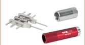
Info | EFLa | NA | OD | WDb | CA | TC | DW | AR Rangec | LWTd | Glass | Performance | Thread | Suggested Spanner Wrench |
|---|---|---|---|---|---|---|---|---|---|---|---|---|---|---|
| 354140-A | 1.5 mm | 0.58 | - | D-ZK3 | Focal Shift / Spot Size |
- | - | |||||||
| C140TMD-A | 6.2 mm | SPW306 | ||||||||||||
| 354710-A | 1.5 mm | 0.53 | 0.5 mmf | S1: Ø1.15 mm S2: Ø1.50 mm |
0.863 mm | 350 - 700 nm | 0.250 mm | D-ZK3 | Focal Shift / Spot Size |
- | - | |||
| C710TMD-A | 6.2 mm | 0.4 mmf,g | M6 x 0.5 | SPW306 |
- EFL is specified at the design wavelength for the unmounted lens.
- WD is specified at the design wavelength.
- The AR coating is designed for 350 - 700 nm, but the substrate material has poor transmittance in the UV (click on the Info Icon
 for details).
 - Lenses with an LWT specification are designed for laser diode collimation; in these cases, the NA, WD, and wavefront are defined based on the presence of a laser window (not included) of the indicated thickness.
- This working distance is measured to the focal point.
- This working distance is measured to the front of the window of the laser diode being collimated.
- Measured from the Mount
| Item # (Unmounted/ Mounted) |
Info | EFLa | NA | OD | WDb | CA | TC | DW | AR Rangec | LWTd | Glass | Performance | Thread | Suggested Spanner Wrench |
|---|---|---|---|---|---|---|---|---|---|---|---|---|---|---|
| 355151-A | 2.0 mm | 0.50 | 3.000 mm | 0.5 mme | S1: Ø1.09 mm S2: Ø2.00 mm |
1.892 mm | 780 nm | 350 - 700 nm | 0.250 mm | Focal Shift / Spot Size Cross Section |
- | - | ||
| C151TMD-A | 6.2 mm | 0.3 mme,f | M6 x 0.5 | SPW306 | ||||||||||
| 355390-A | 2.8 mm | 0.55 | 4.500 mm | 2.2 mmg | S1: Ø3.60 mm S2: Ø3.60 mm |
1.900 mm | 830 nm | 350 - 700 nm | - | D-ZLaF52LA | 390_Asph.pdf | - | - | |
| C390TME-A | 8.2 mm | 2.0 mmg,f | M8 x 0.5 | SPW308 | ||||||||||
| 355392-A | 2.8 mm | 0.60 | 4.000 mm | 1.5 mmg | S1: Ø2.50 mm S2: Ø3.60 mm |
2.240 mm | 830 nm | 350 - 700 nm | - | D-ZLaF52LA | 392_Asph.pdf | - | - | |
| C392TME-A | 6.2 mm | 1.0 mmg,f | M6 x 0.5 | SPW306 | ||||||||||
| 355440-A | 2.8 mm | S1: 0.26 S2: 0.52 |
4.700 mm | S1: 2.0 mme S2: 7.1 mmg |
3.827 mm | 980 nm | 350 - 700 nm | 0.250 mm | D-ZLaF52LA | Focal Shift / Spot Size Cross Section |
- | - | ||
| C440TMD-A | 8.2 mm | S1: 1.9 mme,f S2: 7.1 mmg,h |
M8 x 0.5 | SPW308 |
- EFL is specified at the design wavelength for the unmounted lens.
- WD is specified at the design wavelength.
- The AR coating is designed for 350 - 700 nm, but the substrate material has poor transmittance in the UV (click on the Info Icon for details).
- Lenses with an LWT specification are designed for laser diode collimation; in these cases, the NA, WD, and wavefront are defined based on the presence of a laser window (not included) of the indicated thickness.
- This working distance is measured to the front of the window of the laser diode being collimated.
- Measured from the Mount
- This working distance is measured to the focal point.
- Measured from the Lens
| Item # (Unmounted/ Mounted) |
Info | EFLa | NA | OD | WDb | CA | TC | DW | AR Rangec | LWTd | Glass | Performance | Thread | Suggested Spanner Wrench |
|---|---|---|---|---|---|---|---|---|---|---|---|---|---|---|
| 355660-A | 3.0 mm | 0.52 | 4.000 mm | 1.6 mme | S1: Ø2.35 mm S2: Ø3.60 mm |
2.500 mm | 1550 nm | 350 - 700 nm | - | 660_Asph.pdf | - | - | ||
| C660TME-A | 8.2 mm | 1.3 mme,f | M8 x 0.5 | SPW308 | ||||||||||
| 354330-A | 0.70 | 6.325 mm | 1.8 mme | S2: Ø5.00 mm |
830 nm | - | Focal Shift / Spot Size Cross Section |
- | - | |||||
| C330TMD-A | 9.2 mm | 1.8 mme,f | M9 x 0.5 | SPW301 | ||||||||||
| N414-A | 3.30 mm | 0.47 | 4.50 mm | 1.94 mme | Ø3.52 mm | 3.87 mm | 670 nm | 350 - 700 nm | 0.25 mm | N414_Asph.pdf | - | - | ||
| N414TM-A | 6.22 mm | 1.83 mme,f | M6 x 0.5 | SPW306 |
- EFL is specified at the design wavelength for the unmounted lens.
- WD is specified at the design wavelength.
- The AR coating is designed for 350 - 700 nm, but the substrate material has poor transmittance in the UV (click on the Info Icon for details).
- Lenses with an LWT specification are designed for laser diode collimation; in these cases, the NA, WD, and wavefront are defined based on the presence of a laser window (not included) of the indicated thickness.
- This working distance is measured to the focal point.
- Measured from the Mount
| Item #(Unmounted/ Mounted) |
Info | EFLa | NA | OD | WDb | CA | TC | DW | AR Rangec | LWTd | Glass | Performance | Thread | Suggested Spanner Wrench |
|---|---|---|---|---|---|---|---|---|---|---|---|---|---|---|
| 357610-A | 4.0 mm | 0.62 | 6.325 mm | 1.5 mme | S2: Ø4.80 mm |
2.953 mm | 410 nm | 1.200 mm | Focal Shift / Spot Size Cross Section |
- | - | |||
| C610TMD-A | 9.24 mm | 1.1 mme,f | M9 x 0.5 | SPW301 | ||||||||||
| 357775-A | 4.0 mm | 0.60 | 6.325 mm | 1.9 mme | S1: Ø3.45 mm S2: Ø4.80 mm |
2.898 mm | 408 nm | 350 - 700 nm | 0.250 mm | D-LAK6 | Focal Shift / Spot Size Cross Section |
- | - | |
| C775TMD-A | 9.2 mm | 1.5 mme,f | M9 x 0.5 | SPW301 | ||||||||||
| 354340-A | 4.0 mm | 0.64 | 6.325 mm | 1.5 mme | S1: Ø3.77 mm S2: Ø5.10 mm |
3.097 mm | 685 nm | 350 - 700 nm | 1.200 mm | D-ZK3 | Focal Shift / Spot Size Cross Section |
- | - | |
| C340TMD-A | 9.2 mm | 0.9 mme,f | M9 x 0.5 | SPW301 | ||||||||||
| 355230-A | 4.5 mm | 0.55 | 6.325 mm | 2.8 mme | S1: Ø3.93 mm S2: Ø5.07 mm |
2.708 mm | 780 nm | 350 - 700 nm | 0.250 mm | Focal Shift / Spot Size Cross Section |
- | - | ||
| C230TMD-A | 9.2 mm | 2.4 mme,f | M9 x 0.5 | SPW301 | ||||||||||
| A230-A | 4.51 mm | 0.55 | 6.33 mm | 2.91 mmg | Ø4.95 mm | 2.94 mm | 780 nm | 350 - 700 nm | 0.25 mm | S-NPH1 | A230_Asph.pdf | - | - | |
| A230TM-A | 9.24 mm | 2.53 mmf,g | M9 x 0.5 | SPW301 | ||||||||||
| 354453-A | 4.6 mm | 0.50 | 6.000 mm | 2.0 mme | S1: Ø3.38 mm S2: Ø4.80 mm |
3.135 mm | 655 nm | 350 - 700 nm | 0.275 mm | D-ZK3 | Focal Shift / Spot Size Cross Section |
- | - | |
| C453TMD-A | 9.2 mm | 0.9 mme,f | M9 x 0.5 | SPW301 | ||||||||||
| A390-A | 4.60 mm | 0.53 | 6.00 mm | 2.70 mmg | Ø4.89 mm | 3.10 mm | 655 nm | 350 - 700 nm | 0.275 mm | H-LaK54 | A390_Asph.pdf | - | - | |
| A390TM-A | 9.24 mm | 1.64 mmf,g | M9 x 0.5 | SPW301 |
- EFL is specified at the design wavelength for the unmounted lens.
- WD is specified at the design wavelength.
- The AR coating is designed for 350 - 700 nm, but the substrate material has poor transmittance in the UV (click on the Info Icon for details).
- Lenses with an LWT specification are designed for laser diode collimation; in these cases, the NA, WD, and wavefront are defined based on the presence of a laser window (not included) of the indicated thickness.
- This working distance is measured to the front of the window of the laser diode being collimated.
- Measured from the Mount
- This working distance is measured to the focal point.
| Item # (Unmounted/ Mounted) |
Info | EFLa | NA | OD | WDb | CA | TC | DW | AR Rangec | LWTd | Glass | Performance | Thread | Suggested Spanner Wrench |
|---|---|---|---|---|---|---|---|---|---|---|---|---|---|---|
| 354105-A | 5.5 mm | 0.60 | 7.200 mm | 3.1 mme | S1: Ø4.96 mm S2: Ø6.00 mm |
2.937 mm | 633 nm | 350 - 700 nm | 0.250 mm | D-ZK3 | Focal Shift / Spot Size Cross Section |
- | - | |
| C105TMD-A | 9.2 mm | 2.0 mme,f | M9 x 0.5 | SPW301 |
- EFL is specified at the design wavelength for the unmounted lens.
- WD is specified at the design wavelength.
- The AR coating is designed for 350 - 700 nm, but the substrate material has poor transmittance in the UV (click on the Info Icon for details).
- Lenses with an LWT specification are designed for laser diode collimation; in these cases, the NA, WD, and wavefront are defined based on the presence of a laser window (not included) of the indicated thickness.
- This working distance is measured to the front of the window of the laser diode being collimated.
- Measured from the Mount
| Item # (Unmounted/ Mounted) |
Info | EFLa | NA | OD | WDb | CA | TC | DW | AR Rangec | LWTd | Glass | Performance | Thread | Suggested Spanner Wrench |
|---|---|---|---|---|---|---|---|---|---|---|---|---|---|---|
| 354171-A | 0.30 | 4.700 mm | 3.4 mme | S2: Ø3.70 mm |
3.484 mm | 633 nm | 0.275 mm | D-ZK3 | Focal Shift / Spot Size Cross Section |
- | - | |||
| C171TMD-A | 8.2 mm | 2.8 mme,f | M8 x 0.5 | SPW308 | ||||||||||
| 355110-A | 6.2 mm | 0.40 | 7.200 mm | 2.7 mme | S1: Ø2.93 mm S2: Ø5.00 mm |
5.158 mm | 780 nm | 350 - 700 nm | 0.275 mm | D-ZLaF52LA | Focal Shift / Spot Size Cross Section |
- | - | |
| C110TMD-A | 9.2 mm | 1.6 mme,f | M9 x 0.5 | SPW301 | ||||||||||
| A110-A | 6.24 mm | 0.40 | 7.20 mm | 3.39 mmg | Ø5.00 mm | 5.36 mm | 780 nm | 350 - 700 nm | 0.275 mm | H-LaK54 | A110_Asph.pdf | - | - | |
| A110TM-A | 9.24 mm | 2.39 mmf,g | M9 x 0.5 | SPW301 |
- EFL is specified at the design wavelength for the unmounted lens.
- WD is specified at the design wavelength.
- The AR coating is designed for 350 - 700 nm, but the substrate material has poor transmittance in the UV (click on the Info Icon for details).
- Lenses with an LWT specification are designed for laser diode collimation; in these cases, the NA, WD, and wavefront are defined based on the presence of a laser window (not included) of the indicated thickness.
- This working distance is measured to the front of the window of the laser diode being collimated.
- Measured from the Mount
- This working distance is measured to the focal point.
| Item # (Unmounted/ Mounted) |
Info | EFLa | NA | OD | WDb | CA | TC | DW | AR Rangec | LWTd | Glass | Performance | Thread | Suggested Spanner Wrench |
|---|---|---|---|---|---|---|---|---|---|---|---|---|---|---|
| A375-A | 7.50 mm | 0.30 | 6.51 mm | 5.90 mme | Ø4.50 mm | 2.75 mm | 810 nm | 350 - 700 nm | 0.275 mm | H-LaK54 | A375_Asph.pdf | - | - | |
| A375TM-A | 9.24 mm | 5.59 mme,f | M9 x 0.5 | SPW301 |
- EFL is specified at the design wavelength for the unmounted lens.
- WD is specified at the design wavelength.
- The AR coating is designed for 350 - 700 nm, but the substrate material has poor transmittance in the UV (click on the Info Icon for details).
- Lenses with an LWT specification are designed for laser diode collimation; in these cases, the NA, WD, and wavefront are defined based on the presence of a laser window (not included) of the indicated thickness.
- This working distance is measured to the focal point.
- Measured from the Housing
| Item # (Unmounted/ Mounted) |
Info | EFLa | NA | OD | WDb | CA | TC | DW | AR Rangec | LWTd | Glass | Performance | Thread | Suggested Spanner Wrench |
|---|---|---|---|---|---|---|---|---|---|---|---|---|---|---|
| 354240-A | 8.0 mm | 0.50 | 9.936 mm | 4.9 mme | S2: Ø8.00 mm |
3.434 mm | 780 nm | 0.250 mm | D-ZK3 | Focal Shift / Spot Size Cross Section |
- | - | ||
| C240TMD-A | 12.2 mm | 3.8 mme,f | M12 x 0.5 | SPW302 | ||||||||||
| A240-A | 0.50 | 9.94 mm | 5.92 mmg | Ø8.00 mm | 3.69 mm | 780 nm | 350 - 700 nm | 0.25 mm | A240_Asph.pdf | - | - | |||
| A240TM-A | 12.24 mm | 4.79 mmf,g | M12 x 0.5 | SPW302 |
- EFL is specified at the design wavelength for the unmounted lens.
- WD is specified at the design wavelength.
- The AR coating is designed for 350 - 700 nm, but the substrate material has poor transmittance in the UV (click on the Info Icon for details).
- Lenses with an LWT specification are designed for laser diode collimation; in these cases, the NA, WD, and wavefront are defined based on the presence of a laser window (not included) of the indicated thickness.
- This working distance is measured to the front of the window of the laser diode being collimated.
- Measured from the Mount
- This working distance is measured to the focal point.
| Item # (Unmounted/ Mounted) |
Info | EFLa | NA | OD | WDb | CA | TC | DW | AR Rangec | LWTd | Glass | Performance | Thread | Suggested Spanner Wrench |
|---|---|---|---|---|---|---|---|---|---|---|---|---|---|---|
| 354060-A | 9.6 mm | 0.27 | 6.325 mm | 7.5 mme | S2: Ø5.20 mm |
2.493 mm | 633 nm | 0.250 mm | D-ZK3 | Focal Shift / Spot Size Cross Section |
- | - | ||
| C060TMD-A | 9.2 mm | 7.1 mme,f | M9 x 0.5 | SPW301 |
- EFL is specified at the design wavelength for the unmounted lens.
- WD is specified at the design wavelength.
- The AR coating is designed for 350 - 700 nm, but the substrate material has poor transmittance in the UV (click on the Info Icon for details).
- Lenses with an LWT specification are designed for laser diode collimation; in these cases, the NA, WD, and wavefront are defined based on the presence of a laser window (not included) of the indicated thickness.
- This working distance is measured to the front of the window of the laser diode being collimated.
- Measured from the Mount
| Item # (Unmounted/ Mounted) |
Info | EFLa | NA | OD | WDb | CA | TC | DW | AR Rangec | LWTd | Glass | Performance | Thread | Suggested Spanner Wrench |
|---|---|---|---|---|---|---|---|---|---|---|---|---|---|---|
| 354061-A | 0.24 | 8.9 mme | S2: Ø5.20 mm |
633 nm | 0.250 mm | D-ZK3 | Focal Shift / Spot Size Cross Section |
- | - | |||||
| C061TMD-A | 9.2 mm | 8.5 mme,f | M9 x 0.5 | SPW301 | ||||||||||
| A220-A | 0.26 | 7.20 mm | 7.97 mmg | Ø5.50 mm | 5.00 mm | 633 nm | 350 - 700 nm | 0.25 mm | D-K59 | A220_Asph.pdf | - | - | ||
| A220TM-A | 9.24 mm | 6.91 mmf,g | 0.275 mm | M9 x 0.5 | SPW301 | |||||||||
| 354220-A | 11.0 mm | 0.25 | 7.200 mm | 6.9 mme | S1: Ø4.07 mm S2: Ø5.50 mm |
5.032 mm | 633 nm | 350 - 700 nm | 0.250 mm | D-ZK3 | Focal Shift / Spot Size Cross Section |
- | - | |
| C220TMD-A | 9.2 mm | 5.8 mme,f | M9 x 0.5 | SPW301 | ||||||||||
| 355397-A | 11.0 mm | 0.30 | 7.200 mm | 9.3 mme | S1: Ø6.24 mm S2: Ø6.68 mm |
1.947 mm | 670 nm | 350 - 700 nm | 0.275 mm | Focal Shift / Spot Size Cross Section |
- | - | ||
| C397TMD-A | 9.2 mm | 8.2 mme,f | M9 x 0.5 | SPW301 | ||||||||||
| A397-A | 11.00 mm | 0.30 | 7.20 mm | 9.64 mmg | Ø6.59 mm | 2.20 mm | 670 nm | 350 - 700 nm | 0.275 mm | H-LaK54 | A397_Asph.pdf | - | - | |
| A397TM-A | 9.24 mm | 8.44 mmf,g | M9 x 0.5 | SPW301 |
- EFL is specified at the design wavelength for the unmounted lens.
- WD is specified at the design wavelength.
- The AR coating is designed for 350 - 700 nm, but the substrate material has poor transmittance in the UV (click on the Info Icon for details).
- Lenses with an LWT specification are designed for laser diode collimation; in these cases, the NA, WD, and wavefront are defined based on the presence of a laser window (not included) of the indicated thickness.
- This working distance is measured to the front of the window of the laser diode being collimated.
- Measured from the Mount
- This working distance is measured to the focal point.
| Item # (Unmounted/ Mounted) |
Info | EFLa | NA | OD | WDb | CA | TC | DW | AR Rangec | Glass | Performance | Thread | Suggested Spanner Wrench |
|---|---|---|---|---|---|---|---|---|---|---|---|---|---|
| 354560-A | 13.9 mm | 0.18 | 6.325 mm | 12.1 mmd | S1: Ø4.54 mm S2: Ø5.10 mm |
2.773 mm | 650 nm | 350 - 700 nm | D-ZK3 | 560_Asph.pdf | - | - | |
| C560TME-A | 9.2 mm | 11.7 mmd,e | M9 x 0.5 | SPW301 |
- EFL is specified at the design wavelength for the unmounted lens.
- WD is specified at the design wavelength.
- The AR coating is designed for 350 - 700 nm, but the substrate material has poor transmittance in the UV (click on the Info Icon for details).
- This working distance is measured to the focal point.
- Measured from the Mount
| Item # (Unmounted/ Mounted) |
Info | EFLa | NA | OD | WDb | CA | TC | DW | AR Rangec | LWTd | Glass | Performance | Thread | Suggested Spanner Wrench |
|---|---|---|---|---|---|---|---|---|---|---|---|---|---|---|
| 354260-A | 15.3 mm | 0.16 | 6.500 mm | 12.7 mme | S2: Ø5.00 mm |
2.209 mm | 780 nm | 0.250 mm | D-ZK3 | Focal Shift / Spot Size Cross Section |
- | - | ||
| C260TMD-A | 9.2 mm | 12.4 mme,f | M9 x 0.5 | SPW301 | ||||||||||
| A260-A | 15.29 mm | 0.16 | 6.50 mm | 14.09 mmg | Ø5.00 mm | 2.20 mm | 780 nm | 350 - 700 nm | 0.25 mm | H-LaK54 | A260_Asph.pdf | - | - | |
| A260TM-A | 9.24 mm | 13.84 mmf,g | - | M9 x 0.5 | SPW301 |
- EFL is specified at the design wavelength for the unmounted lens.
- WD is specified at the design wavelength.
- The AR coating is designed for 350 - 700 nm, but the substrate material has poor transmittance in the UV (click on the Info Icon for details).
- Lenses with an LWT specification are designed for laser diode collimation; in these cases, the NA, WD, and wavefront are defined based on the presence of a laser window (not included) of the indicated thickness.
- This working distance is measured to the front of the window of the laser diode being collimated.
- Measured from the Mount
- This working distance is measured to the focal point.
| Item # (Unmounted/ Mounted) |
Info | EFLa | NA | OD | WDb | CA | TC | DW | AR Rangec | LWTd | Glass | Performance | Thread | Suggested Spanner Wrench |
|---|---|---|---|---|---|---|---|---|---|---|---|---|---|---|
| 354280-A | 18.4 mm | 0.15 | 6.50 mm | 15.9 mme | S2: Ø5.50 mm |
780 nm | 0.250 mm | D-ZK3 | Focal Shift / Spot Size Cross Section |
- | - | |||
| C280TMD-A | 9.2 mm | 15.6 mme,f | M9 x 0.5 | SPW301 | ||||||||||
| A280-A | 18.40 mm | 0.15 | 6.50 mm | 17.13 mmg | Ø5.50 mm | 2.17 mm | 780 nm | 350 - 700 nm | 0.25 mm | H-LaK54 | A280_Asph.pdf | - | - | |
| A280TM-A | 9.24 mm | 16.88 mmf,g | - | M9 x 0.5 | SPW301 |
- EFL is specified at the design wavelength for the unmounted lens.
- WD is specified at the design wavelength.
- The AR coating is designed for 350 - 700 nm, but the substrate material has poor transmittance in the UV (click on the Info Icon for details).
- Lenses with an LWT specification are designed for laser diode collimation; in these cases, the NA, WD, and wavefront are defined based on the presence of a laser window (not included) of the indicated thickness.
- This working distance is measured to the front of the window of the laser diode being collimated.
- Measured from the Mount
- This working distance is measured to the focal point.