 Products Home / Fiber Components / Collimation / Coupling / Reflective Collimators / Reflective Collimators, UV-Enhanced Aluminum Coating
Reflective Collimators, UV-Enhanced Aluminum Coating
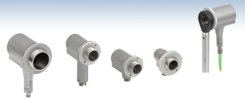
- UV-Enhanced Aluminum Collimators/Couplers with Reflected Focal Lengths of 7.0 mm, 15.0 mm, 33.0 mm, or 50.8 mm
- Maximum Fiber NA without Clipping the Beam: 0.40, 0.30, 0.15, or 0.19
- Free From Chromatic Aberrations
RC12SMA-F01
SMA Connector
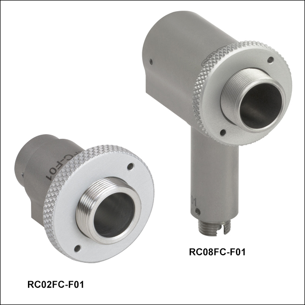
RC08FC-F01
FC/PC Connector
RC04APC-F01
FC/APC Connector
RC02SMA-F01
SMA Connector
RC12APC-F01
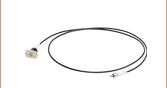
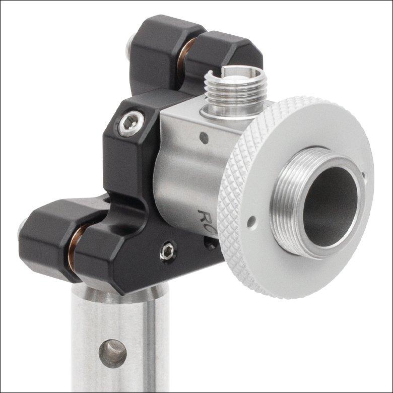
Reflective Collimator
with Patch Cable
Shown Mounted to an
LMR1 on a Ø1/2" Post


Please Wait
| Key Specificationsa | ||||
|---|---|---|---|---|
| Item # Prefix | RC02 | RC04 | RC08 | RC12 |
| Max Fiber Numerical Aperture (NA) | 0.40 | 0.30 | 0.15 | 0.19 |
| Reflected Focal Length (RFL) | 7.0 mm | 15.0 mm | 33.0 mm | 50.8 mm |
| External Threading of Housing | SM05 (0.535"-40) | SM1 (1.035"-40) | ||
| Clear Aperture | Ø7.5 mm | Ø11.0 mm | Ø22.0 mm | |
| Reflectance (Avg., AOI = 45°) | >90% (250 nm - 450 nm) | |||
Click to Enlarge
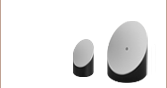
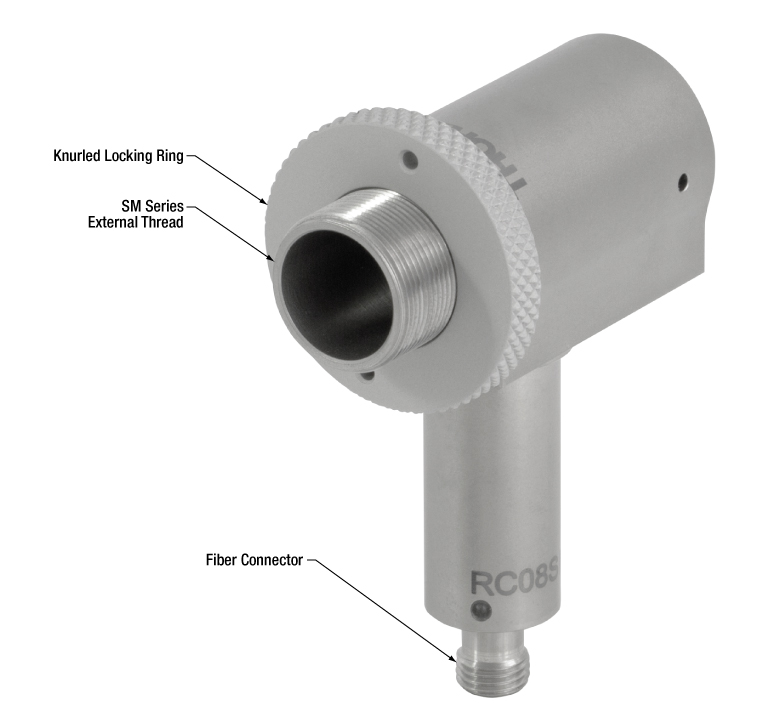
The housings of the RC02, RC04, and RC08 collimators have SM05 (0.535"-40) external threads while the RC12 collimator has SM1 (1.035"-40) external threads. A knurled locking ring included with all collimators enables secure mounting of the optic. Please see the Mounting Options tab for details.
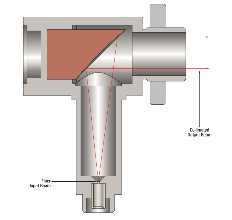
Click to Enlarge
Collimated Light from an Optical Fiber Using an RCxx-F01 Series Collimator (These collimators can also be used in reverse for coupling into a multimode fiber.)
Features
- Free from Chromatic Aberrations for Collimation Over the Mirror's Reflection Band
- UV-Enhanced Aluminum Coating (250 - 450 nm) Offers High Reflection
- Ravg > 90% (250 nm - 450 nm)
- Reflected Focal Lengths of 7.0 mm, 15.0 mm, 33.0 mm, or 50.8 mm
- Great for Coupling Polychromatic Light into Multimode Fiber
- FC/PC, FC/APC, or SMA Connector Options Available
- Surface Roughness: <100 Å (RMS)
- Ø7.5 mm, Ø11.0 mm, or Ø22.0 mm Clear Aperture
- Maximum Fiber NA without Clipping the Beam: 0.40, 0.30, 0.15 or 0.19 (RC02x-F01, RC04x-F01,
RC08x-F01 or RC12x-F01, Respectively) - Non-Magnetic Stainless Steel Housing
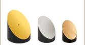
Thorlabs' UV-Enhanced Aluminum Reflective Collimators are based on a 90° off-axis parabolic (OAP) mirror. Metallic mirrors, unlike lenses, have a focal length that remains constant over a broad wavelength range. Due to this intrinsic property, parabolic mirror collimators do not need to be adjusted to accommodate various wavelengths of light, making them ideal for use with polychromatic light. Common applications include systems that utilize multiple wavelengths that need to be collimated, collimation/coupling in the UV, and coupling polychromatic light into large-core multimode fiber.
These UV-enhanced aluminum reflective collimators offer excellent reflectivity within the 250 nm - 450 nm wavelength range; please see the Specs tab for more information. In multiple-wavelength systems operating in the UV and visible, these reflective collimators can be used to both couple polychromatic collimated light into large-core multimode fiber or collimate polychromatic light emitted by optical fibers. When collimating light from a multimode patch cable, the fiber NA should be ≤0.40 (RC02), ≤0.30 (RC04), ≤0.15 (RC08), or ≤0.19 (RC12) to avoid clipping light on the housing. Note too that, in general, light from a multimode fiber cannot be well collimated. For more information on how to optimize coupling of light from an optical fiber, please see the Collimation Tutorial tab.
The RC02, RC04, and RC08 reflective collimator housings are equipped with external SM05 (0.535"-40) threads while the RC12 housing has external SM1 (1.035"-40) threads. This makes them directly compatible with our SM05- or SM1-threaded optomechanics, such as the LMR05(/M) or LMR1(/M) lens mounts, respectively. The backs of the RC02 collimators are machined down to Ø1/2", enabling direct mounting into a Ø1/2" kinematic mount. Furthermore, the RC02, RC04, and RC08 housing may be directly mounted to Ø1" kinematic mounts by removing the knurled ring on the front of the housing, holding the housing behind the kinematic mount's Ø1" counterbore, and then rethreading the knurled ring over the back lip of the counterbore and onto the housing using an SPW909 Spanner Wrench or an SPW801 Adjustable Spanner Wrench. The collimator can then be secured by tightening the mount's setscrew. Please see the Mounting Options tab for more details.
Scattering from the mirror surface is minimal (~2% @ 633 nm) and results from the <100 Å RMS surface roughness achieved by the diamond turning process used to manufacture the off-axis parabolic mirror.
For the 450 nm - 20 µm range, Thorlabs also offers several types of collimators with our protected silver coating: Reflective Collimators for large NAs, Adjustable Focus Reflective Collimators, and Compact Collimators for easy integration into a cage system.
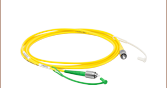
Fiber Patch Cables for Reflective Collimators
Thorlabs offers single mode, polarization-maintaining, or multimode fiber optic patch cables for both coupling and collimating applications. If you cannot find the appropriate stock patch cable for your application, custom patch cables with same-day shipping are also available.
| Specifications | ||||||||||||
|---|---|---|---|---|---|---|---|---|---|---|---|---|
| Item # Prefix | RC02 | RC04 | RC08 | RC12 | ||||||||
| Fiber Connector | FC/PC | FC/APC | SMA | FC/PC | FC/APC | SMA | FC/PC | FC/APC | SMA | FC/PC | FC/APC | SMA |
| Clear Aperture | Ø7.5 mm | Ø11.0 mm | Ø11.0 mm | Ø22.0 mm | ||||||||
| Typical Collimated Beam Diameter (1/e2)a |
Ø1.5 mm (SM400 at 450 nm) Ø1.3 mm (SM600 at 633 nm) Ø1.5 mm (780HP at 780 nm) Ø1.3 mm (SMF-28-J9 at 1550 nm) Ø2.2 mm (SM1950 at 2 µm) |
Ø3.1 mm (SM400 at 450 nm) Ø2.8 mm (SM600 at 633 nm) Ø3.3 mm (780HP at 780 nm) Ø2.9 mm (SMF-28-J9 at 1550 nm) Ø4.7 mm (SM1950 at 2 µm) |
Ø6.8 mm (SM400 at 450 nm) Ø6.2 mm (SM600 at 633 nm) Ø7.2 mm (780HP at 780 nm) Ø6.3 mm (SMF-28-J9 at 1550 nm) Ø10.2 mm (SM1950 at 2 µm) |
Ø10.5 mm (SM400 at 450 nm) Ø9.5 mm (SM600 at 633 nm) Ø11.0 mm (780HP at 780 nm) Ø9.6 mm (SMF-28-J9 at 1550 nm) Ø15.8 mm (SM1950 at 2 µm) |
||||||||
| Full Angle Beam Divergenceb | 0.023° (SM400 at 450 nm) 0.035° (SM600 at 633 nm) 0.037° (780HP at 780 nm) 0.088° (SMF-28-J9 at 1550 nm) 0.067° (SM1950 at 2 µm) |
0.011° (SM400 at 450 nm) 0.016° (SM600 at 633 nm) 0.018° (780HP at 780 nm) 0.040° (SMF-28-J9 at 1550 nm) 0.031° (SM1950 at 2 µm) |
0.005° (SM400 at 450 nm) 0.007° (SM600 at 633 nm) 0.008° (780HP at 780 nm) 0.018° (SMF-28-J9 at 1550 nm) 0.014° (SM1950 at 2 µm) |
0.003° (SM400 at 450 nm) 0.005° (SM600 at 633 nm) 0.005° (780HP at 780 nm) 0.012° (SMF-28-J9 at 1550 nm) 0.009° (SM1950 at 2 µm) |
||||||||
| Maximum Fiber Numerical Aperture (NA) |
0.40 | 0.30 | 0.15 | 0.19 | ||||||||
| Reflected Focal Length (RFL) | 7.0 mm | 15.0 mm | 33.0 mm | 50.8 mm | ||||||||
| Parent Focal Length (PFL)c | 3.5 mm | 7.5 mm | 16.5 mm | 25.4 mm | ||||||||
| Coating | UV-Enhanced Aluminum | |||||||||||
| Wavelength Range | 250 - 450 nm | |||||||||||
| Reflectance (Avg., AOI = 45°) | >90% | |||||||||||
| Surface Quality | 40-20 Scratch-Dig | |||||||||||
| Surface Roughness | <100 Å RMS | |||||||||||
| Reflected Wavefront Error | λ/4 RMS at 633 nm | |||||||||||
| Pointing Errord | <10 mrad | <10 mrad | - | <10 mrad | <10 mrad | - | <10 mrad | <10 mrad | - | <10 mrad | <10 mrad | - |
Click to Enlarge
Excel Spreadsheet with Raw Data Over the 250 nm - 20 µm Range
for UV-Enhanced Aluminum, 45° AOI
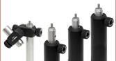
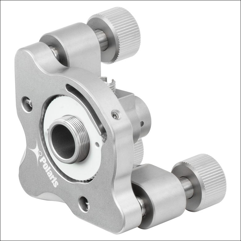
Mirror Mounts
The Ø1", 4.0 mm thick knurled locking ring of the RC02x, RC04x, and RC08x reflective collimators can be used as the mounting surface to secure the collimator into a mirror mount for Ø1" optics, such as the POLARIS-K1E Ø1" side optic retention mount shown in the middle image below. Other mirror mounts or other optic mounts capable of securing a 4.0 mm thick optic can also be used. The RC02x, RC04x, and RC08x collimators feature an SM05 (0.535"-40) external threading which also enables mounting to Thorlabs' SM05-threaded kinematic mirror mounts. The RC12x collimator features an external SM1 (1.035"-40) threading that can be used to mount the collimator to an SM1-threaded kinematic mirror mount or to a mirror mount for Ø2" optics by using an SM1-threaded adapter such as the AD2T adapter. The RC02x collimator can be mounted using the Ø1/2" (12.7 mm) rear surface as shown in the image below.
Click to Enlarge An RC02x Collimator Secured in a KM05 Kinematic Mirror Mount using the rear mounting surface.
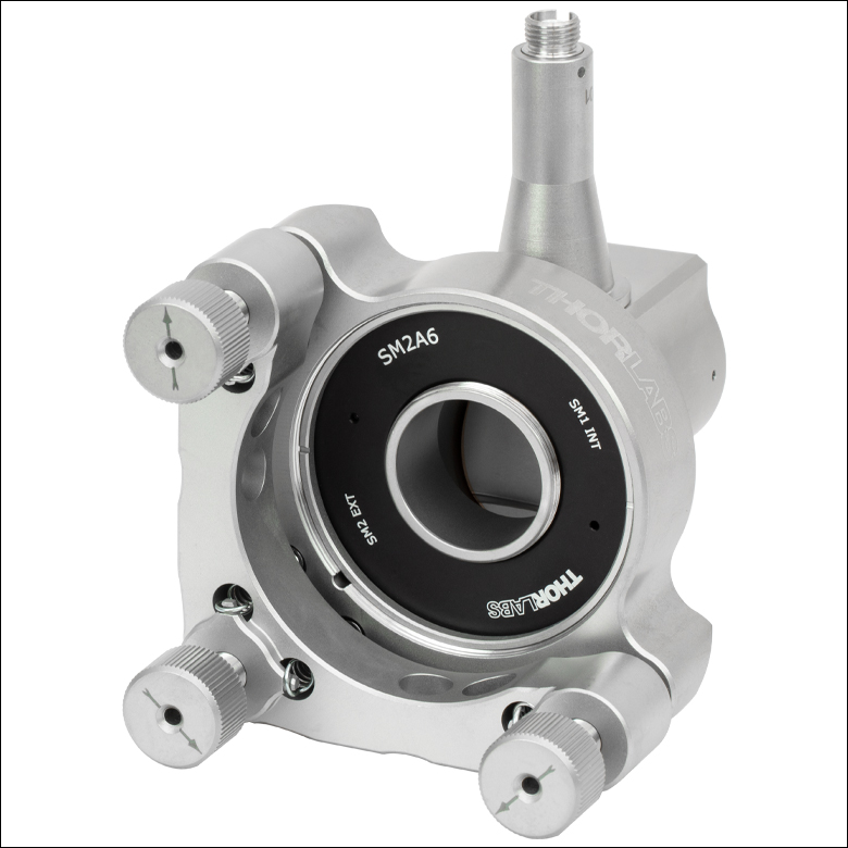
Click to Enlarge An RC12x Collimator in a POLARIS-K2T Ø2" Mount using an SM2A6 adapter with SM1-internal and SM2-external threads.
Cage System and Lens Tube Integration
The RC02x, RC04x, and RC08x collimators can be directly integrated into a cage system using the external SM05 (0.535"-40) threading on the collimator housing and an SM05 internally threaded cage component such as Thorlabs' CP32(/M) cage plate for 30 mm cage systems. Similarly, the RC12x collimator can be directly mounted into a cage system using the external SM1 (1.035"-40) threading on the collimator housing and a compatible cage system component such as the CP33(/M) cage plate for 30 mm cage systems.
The SM05 (0.535"-40) or SM1 (1.035"-40) external threading on the RC0x or RC12x collimators, respectively, can also be used to mount a compatible SM-threaded lens tube or other compatible optic for easy system integration.
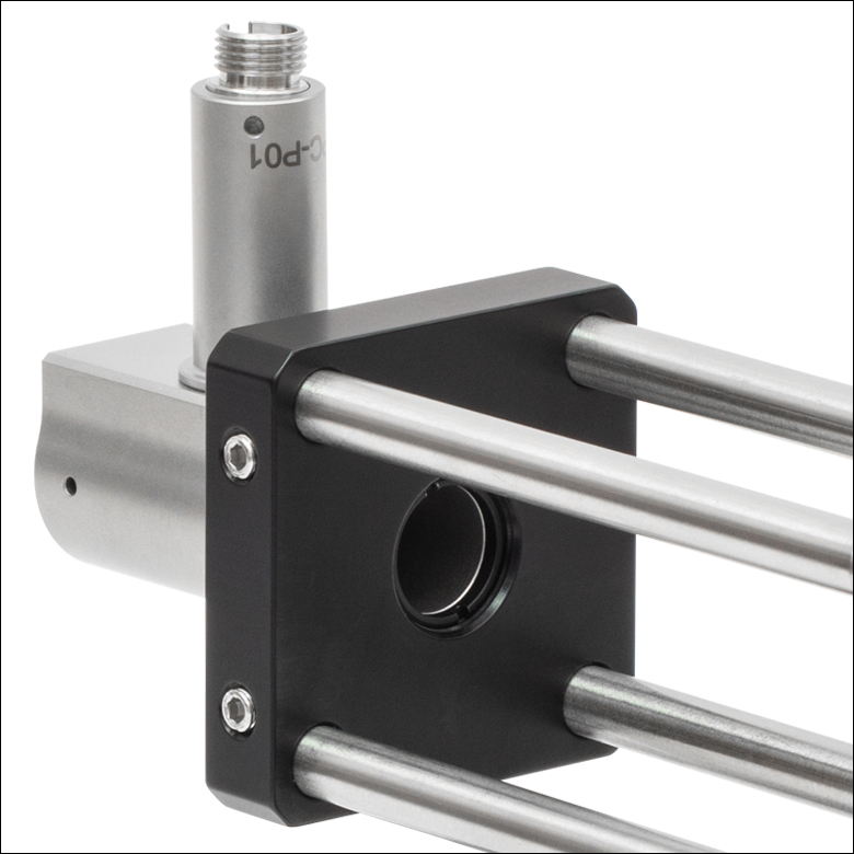
Click to Enlarge An RC08x Reflective Collimator is mounted to a CP32 30 mm Cage Plate using the SM05 (0.535"-40) external threads.
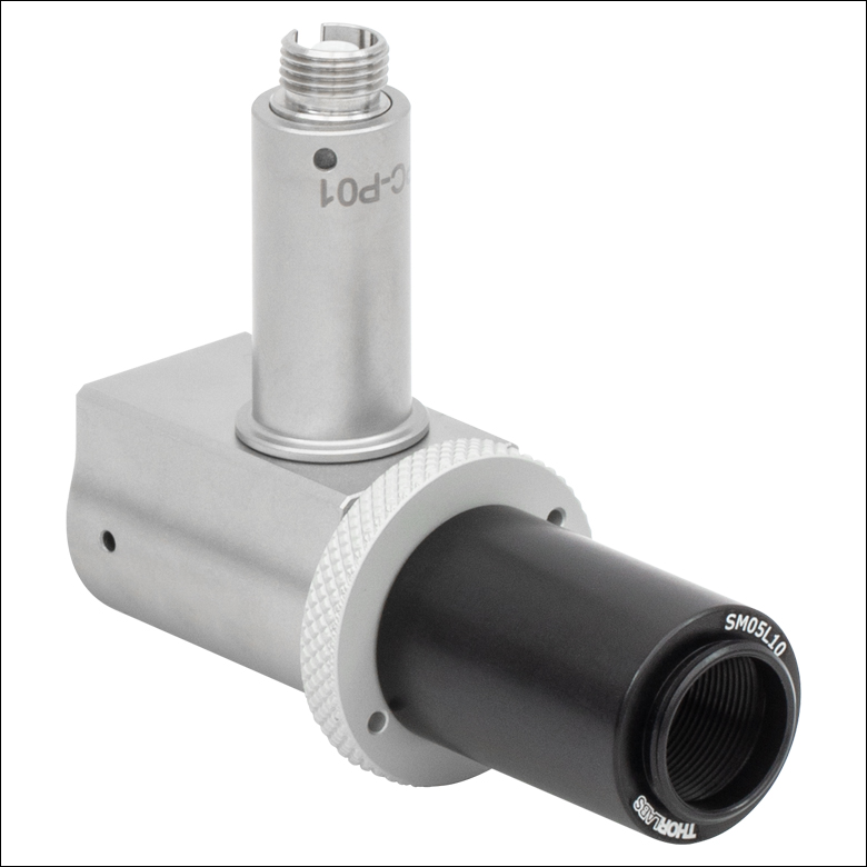
Click to Enlarge An RC08x Reflective Collimator with an SM05L10 Lens Tube attached using the SM05 (0.535"-40) external threads.
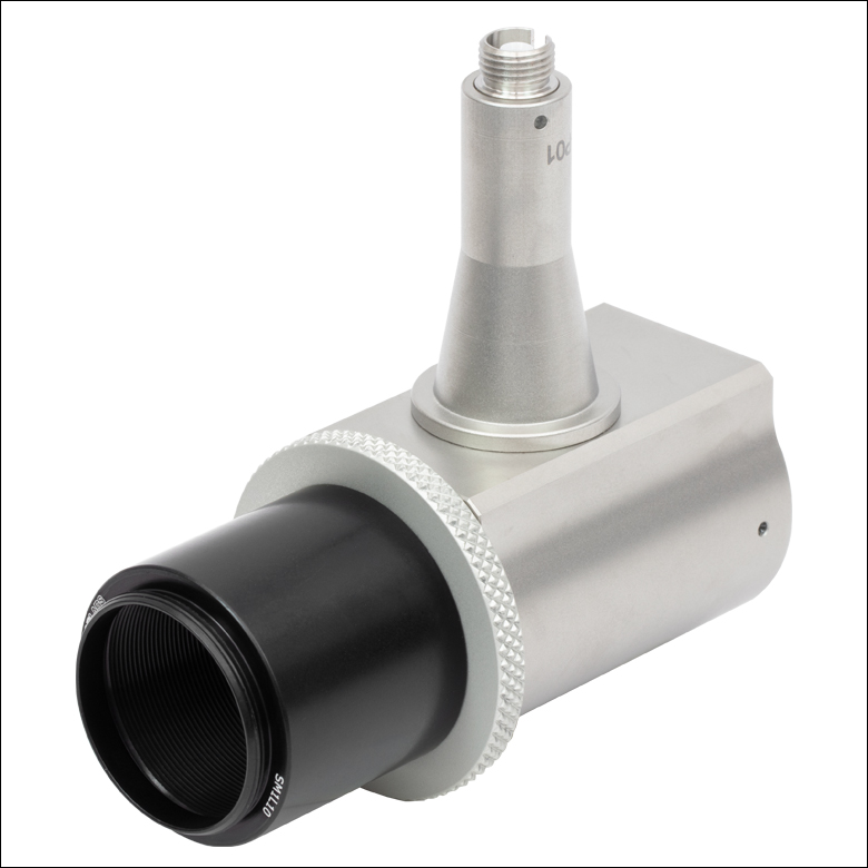
Click to Enlarge An RC12x Reflective Collimator with an SM1L10 Lens Tube attached using the SM1 (1.035"-40) external threads.
Collimating Light Tutorial
Collimating Light from a Single Mode Fiber with a Reflective Collimator
When collimating light from single-mode fibers, the Reflective Fiber Collimators produce beams with large waist diameters and low divergence. The graphs below illustrate the theoretical 1/e2 beam diameter as a function of propagation distance for four different SM fiber-coupled laser wavelengths using our reflective collimators. The effect of changing the fiber or the wavelength can be estimated using the theoretical approximations below.
Theoretical Approximation of the Divergence Angle of an Output Beam
The divergence angle can be approximated theoretically using the formula below as long as the light emerging from the fiber has a Gaussian intensity profile. Therefore, the formula works well for single mode (SM) fibers.
The full divergence angle of the output beam using an SM fiber in degrees is approximated by

where θSM is the divergence angle of the beam after collimation, MFD is the mode field diameter of the fiber, and RFL is the reflected focal length of the reflective collimator. The MFD and RFL must have the same units in this equation.
Example Calculation:
When the RC04APC-F01 collimator (RFL = 15.0 mm) is used with the P3-630A-FC-1 SM patch cable (MFD = 4.3 µm), the divergence angle is:
θSM ≈ (0.0043 mm / 15.0 mm) x (180 / 3.1416) ≈ 0.016° or 0.29 mrad.
Theoretical Approximation of the Output Beam Diameter
The 1/e2 output beam diameter can be found using the approximation

where λ is the wavelength of light being used, MFD is the mode field diameter of the fiber, and RFL is the reflected focal length of the reflective collimator.
Example Calculation:
When the RC04APC-F01 collimator (RFL = 15.0 mm) is used with the P3-630A-FC-1 SM patch cable (MFD = 4.3 µm) at λ = 633 nm = 0.633 µm, the output beam diameter is:
d = 4 x 0.633 µm x [15.0 mm / (3.1416 x 4.3 µm)] = 2.8 mm.
Click to Enlarge
Click Here for Theoretical Data
This data is calculated for our SM400, SM600, 780HP, and SMF-28-J9 single mode fibers and our RC04x-F01 reflective collimators.
Click to Enlarge
Click Here for Theoretical Data
This data is calculated for our SM400, SM600, 780HP, and
SMF-28-J9 single mode fibers and our RC02x-F01 reflective collimators.
Click to Enlarge
Click Here for Theoretical Data
This data is calculated for our SM400, SM600, 780HP, and
SMF-28-J9 single mode fibers and our RC12x-F01 reflective collimators.
Click to Enlarge
Click Here for Theoretical Data
This data is calculated for our SM400, SM600, 780HP, and
SMF-28-J9 single mode fibers and our RC08x-F01 reflective collimators.
Collimating Light from a Multimode Fiber with a Reflective Collimator
Click to Enlarge
Low-NA Fiber: The green line indicates the envelope of the beam as it diverges and is collimated by the OAP mirror.
Click to Enlarge
High-NA Fiber: The red line indicates the envelope of the beam that is clipped by the collimator housing. The dashed green line shows the portion of the beam that is collimated by the OAP mirror.
The geometrical ray model can be used to describe the collimation of light from multimode (MM) fibers. Consider an off-axis point on the MM core. Light from this point will generate a collimated beam at an angle to the optical axis of the off-axis parabolic (OAP) mirror. Superimposing beams from all points on the MM core results in an output beam with significant divergence, unlike the output from the SM fiber described above. The graphs below show the calculated beam diameter as a function of distance from the reflective couplers for three different MM fibers.
Theoretical Approximation of the Divergence Angle of an Output Beam
The full angle divergence of an output beam generated from a MM fiber can be approximated with the help of the reflected focal length (RFL) of the reflective collimator and the core diameter of the MM fiber as follows:
where θMM is the divergence angle of the beam after collimation, calculated in degrees.
Example Calculation:
When the RC12SMA-F01 collimator (RFL = 50.8 mm) is used with the M96L01 MM patch cable (Core Diameter = 105 µm), the full divergence angle is:
θMM ≈ (0.105 mm / 50.8 mm) x (180 / 3.1416) ≈ 0.118° or 2.1 mrad.
Theoretical Approximation of the Output Beam Diameter
Based on the ray model, the beam diameter as a function of distance from the reflective collimator and NA can be approximated with the following relation:

The equation above shows that the beam diameter is more strongly affected by the numerical aperture (NA) of the fiber close to the reflecting mirror, whereas the core diameter more strongly affects the beam diameter far from the collimator.
The graphs below illustrate the approximated beam diameter as a function of the distance from the collimator for three different MM fibers (FG010LDA, FG025LJA, FG105LVA), all with an NA = 0.1. These results are independent of wavelength and connector type, but depend on the reflected focal length of the collimator.
Using MM fibers with NAs >0.40, >0.30, >0.15, and >0.19 for the RC02x-F01, RC04x-F01, RC08x-F01, and RC12x-F01 collimators, respectively, will cause light to be clipped by the housing of the collimators before it reaches the output. Therefore, when collimating light from a MM patch cable, the fiber NA should be ≤0.40, ≤0.30, ≤0.15, and ≤0.19 for the RC02x-F01, RC04x-F01, RC08x-F01, or RC12x-F01 collimators, respectively, to avoid clipping light on the housing.
Aside from all these considerations based on simple paraxial optics, please keep in mind that a perfect off-axis parabola can only collimate light without aberrations from a point source, located at the mirror's focal point. The further the point is away from the optical axis or the larger the core of the MM fiber, the larger the introduced optical aberrations for the off-axis rays of the extended source. Finally, the off-axis points of the extended source cannot be perfectly collimated. The effects of aberrations can, however, be minimized by increasing the reflected focal length of the reflective collimator or by increasing the wavelength.
Click to Enlarge
Click Here for Theoretical Data
This data is calculated for our FG010LDA, FG025LJA, and FG105LVA multimode fibers and our RC04x-F01 reflective collimators, independent of wavelength.
Click to Enlarge
Click Here for Theoretical Data
This data is calculated for our FG010LDA, FG025LJA, and FG105LVA multimode fibers and our RC02x-F01 reflective collimators, independent of wavelength.
Click to Enlarge
Click Here for Theoretical Data
This data is calculated for our FG010LDA, FG025LJA, and FG105LVA multimode fibers and our RC12x-F01 reflective collimators, independent of wavelength.
Click to Enlarge
Click Here for Theoretical Data
This data is calculated for our FG010LDA, FG025LJA, and FG105LVA multimode fibers and our RC08x-F01 reflective collimators, independent of wavelength.

Insights into Off-Axis Parabolic Mirrors
Scroll down to read about the unique properties of off-axis parabolic (OAP) mirrors and how to take advantage of them:
- Why a Parabolic Mirror Instead of a Spherical Mirror?
- Benefit of an Off-Axis Parabolic Mirror
- Directionality of OAP-Mirror-Based Reflective Collimators
Click here for more insights into lab practices and equipment.
Why a Parabolic Mirror Instead of a Spherical Mirror?
Click to Enlarge
Figure 187B Spherical mirrors do not reflect all rays in a collimated beam through a single point. A selection of intersections in the focal volume are indicated by black dots.
Click to Enlarge
Figure 187A Parabolic mirrors have a single focal point for all rays in a collimated beam.
Parabolic mirrors perform better than spherical mirrors when collimating light emitted by a point source or focusing a collimated beam.
Focusing Collimated Light
Parabolic mirrors (Figure 187A) focus all rays in an incoming, collimated light beam to a diffraction-limited spot. In contrast, concave spherical mirrors (Figure 187B) concentrate incoming collimated light into a volume larger than a diffraction-limited spot. The size of the spherical mirror's focal volume can be reduced by decreasing the diameter of the incoming collimated beam.
Collimating Light from a Point Source
A point source emits light in all directions. When this highly divergent light source is placed at the focal point of a parabolic mirror, the output beam is highly collimated. If the point source were ideal, all reflected rays would be perfectly parallel with one another.
When a point source is placed within a spherical mirror's focal volume, the output beam is not as well collimated as the beam provided by a parabolic mirror. Different rays from the point source are not perfectly parallel after reflection from the spherical mirror, but two reflected rays will be more nearly parallel when they reflect from more closely spaced points on the spherical mirror's surface. Consequently, the quality of the collimated beam can be improved by reducing the area of the reflective surface. This is equivalent to limiting the angular range over which the source in the focal volume emits light.
Choosing Between Parabolic and Spherical Mirrors
A parabolic mirror is not always the better choice. Beam diameter, cost constraints, space limitations, and performance requirements of an application all influence selection. Beam diameter is a factor, since the performance of these two mirrors is more similar when the beam diameter is smaller. Parabolic mirrors are more expensive, since their reflective profiles are more difficult to fabricate. Parabolic mirrors are also typically larger. Improved performance may or may not be more important than the difference in cost and physical size.
Date of Last Edit: Dec. 4, 2019
Benefit of an Off-Axis Parabolic Mirror
Click to Enlarge
Figure 187D An off-axis parabolic mirror can be thought of as a section of the larger parabolic shape. Both have the same focal point, but it is more accessible in the case of an OAP mirror.
Click to Enlarge
Figure 187C The focal point of an on-axis parabolic mirror is close to the reflective surface, and typically surrounded by the reflective surface, which makes the focal point difficult to access.
One of the primary benefits of a concave parabolic mirror is its single focal point. All rays travelling parallel to the mirror's axis are reflected through this point. This is useful for a range of purposes, including imaging and manufacturing applications that require focusing laser light to a diffraction limited spot.
There are a few negatives associated using with using conventional parabolic mirrors, which are symmetric around the focal point (Figure 187C). One is that the sides of the mirror generally obstruct access to the focus. Another is that when the mirror is used to collimate a divergent light source, the housing of the light source blocks a portion of the collimated beam. In particular, light emitted at small angles with respect to the optical axis of the mirror is typically obstructed.
An off-axis parabolic (OAP) mirror (Figure 187D) is one solution to this problem. The reflective surface of this mirror is parabolic in shape, but it is not symmetric around the focal point. The reflective surface of the OAP corresponds to a section of the parent parabola that is shifted away from the focal point. The section chosen depends on the desired angle and / or distance between the focal point and the center of the mirror.
Date of Last Edit: Dec. 4, 2019
Directionality of OAP-Mirror-Based Reflective Collimators
Click to Enlarge
Figure 187F The reflective element of the collimator is an off-axis parabolic mirror. The mirror's substrate is highlighed in red. The shape of the reflective surface is a segment of the parabolic curve displaced from the vertex. The focal points of the parent parabola and the OAP mirror coincide.
Click to Enlarge
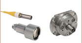
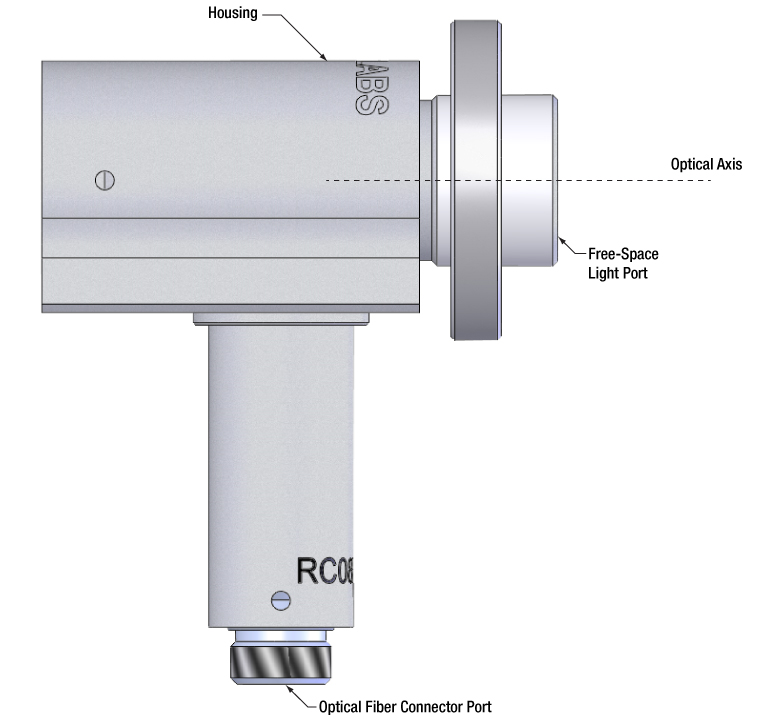
Figure 187E Thorlabs offers reflective collimators that include a port for an optical fiber connector and a port for free space, collimated light that propagates parallel to the optical axis.
The two ports on Thorlabs' reflective collimators are not interchangeable. One port accepts an optical fiber connector and requires the highly divergent light of a point source. The other port is designed solely for collimated, free-space light (Figure 187E).
Free Space Port
Light input to this port should be collimated and directed parallel to the optical axis. Diverging light from a fiber end face, a laser diode, or other source should not be input. This light would not be collimated at the fiber connector port or coupled into the fiber connected to the fiber port.
Optical Fiber Connector Port
This port aligns the fiber's end face with the focal point of the mirror. Since the fiber's end face approximates a point source placed at the focal point, a collimated beam is output from the free-space port. The alignment of the fiber end face with the focal point is also the reason that all light input to the free-space light port should be collimated and directed parallel to the optical axis.
Source of Directionality
The collimator's directionality is a consequence of using a non-rotationally symmetric, off-axis parabolic (OAP) mirror as the reflective element (Figure 187F). The cut-away view illustrates that the fiber's end face is positioned at the focal point of the parent parabola, which is also the focal point of the OAP mirror.
Date of Last Edit: Dec. 4, 2019
| Posted Comments: | |
Sebastian Schlichting
(posted 2024-05-16 07:58:25.247) Es wäre gut, wenn es die Kollimatoren (auch RC08SMA) optional mit verstellbarem Fokus geben würde. Der SMA-Anschluss ist ja mit einer Madenschrauve fixiert und verstellbar. Leider ist alles nachträglich verklebt. Einfach optional den Kleber weg lassen! fnero
(posted 2024-05-17 03:05:30.0) Thank you for your feedback and improvement suggestion. RC-collimators with adjustable focus is in development. We can also offer unglued fiber connectors on request for custom alignment, if needed. Won-il Lee
(posted 2024-04-30 13:41:39.093) I would like to know what the reflectance is in the wavelength range of 1200nm to 1700nm. mkarlsson
(posted 2024-04-30 08:54:55.0) Thank you for your inquiry! An excel sheet with raw data on the reflectance from 250 nm to 20 µm can be found under the specs tab. I've also reached out to you directly with this information. 高 成
(posted 2023-11-20 13:58:20.603) 这个器件的光学调整架可不可以用 KM05? jeklof
(posted 2023-11-21 04:18:02.0) "Can KM05 be used as the optical kinematic mount for this device?”
-It is possible but it would be, due to stability reasons, be better to use for example a SM-threaded kinematic mount or a kinematic V-mount. Please reach out to techsupport-cn@thorlabs.com to discuss this further. Rick Harrison
(posted 2022-11-11 08:42:10.56) I would love a SM2 version of this with the UV -enhanced fiber collimator. cdolbashian
(posted 2022-11-16 03:42:48.0) Thank you for reaching out to us with this inquiry Rick. Unfortunately at this time, we cannot fulfill this type of custom request, though I have submitted this internally as a product request, as it will surely be a good product for a future release. Trung Ngo
(posted 2022-06-24 14:02:22.517) Dear Ladies and Gentlemen,
1- I have Fiber-Coupled LEDs / MWWHF2 with an SMA connector and I am trying to use a reflective collimator to produce a narrow collimated beam. I think the RC02SMA-F01 is the suitable one. I would like to confirm the compatibility of those devices and I would like to ask whether this reflective collimator significantly reduces the light intensity.
Our previous setup (MWWHF2, P2-460B-PCSMA-1 Fiber, RC02FC-P01) did not work well. The output beam was weak and not collimated.
Is the RC02SMA-F01 compatible with the KM05CP/M mount?
2- If you have any alternative solution to produce a LED narrow beam, could you suggest me?
Regards,
Trung ksosnowski
(posted 2022-06-24 04:05:31.0) The reflective collimators are good for broadband sources due to their achromaticity. The RC02x variants have the shortest focal length and smallest beam output of this series. The external SM05 threading is correct size to mount in the KM05CP(/M) however this mount is not threaded so would use the locking screw to secure it in place. Producing a narrow beam from a naturally large area and divergent source can be challenging, and will come at the cost of optical power. Using SM fiber will act as a spatial filter, and while this reduces power, this also reduces the etendue of the LED output enabling high quality beam output from a collimator. When a higher power with narrower beam is required, sometimes a laser emitter can be more effective. The drawback is that laser spectra are typically narrow. Regarding your previous setup, I've reached out directly to discuss this application further. Felix Koch
(posted 2022-01-25 13:29:06.23) Dear ladies and gentlemen,
we want to use your OAP-collimators for free-space-coupling with 200 or 400 µm multimode fibers with a broad spectrum of 190...800 nm. Can you provide the reflectivity for the whole spectrum for UV-enhanced Al? Could you also provide these products with bare Al coating? To our experiance this is the best option for broad spectrum applications. Otherwise a shift of the maximum from 250 to 200 nm would also be of interest because we want to optimize throughput for the DUV range. We need quantities of 5...10 for the moment, but we often deal with similar problems.
I would appreciate if you were open for further discussions on this matter!
Best regards
Felix cdolbashian
(posted 2022-01-31 05:19:40.0) Thank you for reaching out to us here at Thorlabs Felix. I have reached out to you with tabulated extended reflectivity data to the range of interest. Regarding a custom solution I have forwarded your request to our Solutions Team. For future custom requests, please feel free to email our Solutions Team at Techsales@thorlabs.com ivan.maleev
(posted 2017-08-04 17:03:55.017) Do you have available RC02 & RC04 reflective collimators with coatings that extend down to 200nm? tfrisch
(posted 2017-08-16 02:41:08.0) Hello, thank you for contacting Thorlabs. I will post your need in our internal engineering forum, but at this time, our UV-enhanced coating is only suitable down to 250nm. ericb
(posted 2017-07-13 08:08:03.193) Hi,
We are interested in a vacuum compatible version of this reflective collimator. What would it take to make this, or a similar item vacuum compatible?
Best Regards,
Eric tfrisch
(posted 2017-07-28 02:39:50.0) Hello, thank you for contacting Thorlabs. I will reach out to you for details for a quote. user
(posted 2017-02-19 23:21:30.493) What about the reflected wavefront error.? Is there any estimation? tfrisch
(posted 2017-02-20 10:15:49.0) Hello, thank you for contacting Thorlabs. These collimators use our stock Off Axis Parabolic Mirrors, so the RWE spec of wave/4 at 633nm will hold for these as well. j.hood
(posted 2016-01-18 17:53:21.47) How would one go about calculating the collimated beam divergence for multimode fibre?
For example if a Dia. 600μm, 0.22NA fibre is used with λ=337nm, what would be the expected divergence of the collimated beam? besembeson
(posted 2016-01-20 10:26:59.0) Response from Bweh at Thorlabs USA: The divergence for multimode fibers can be estimated based on the chiefray of the outer field point of fiber. Depending on the focal length of the reflective collimator, you may use the expression we have at the following link, under the tab "Specs" to estimate the full divergence angle, with D replaced by your fiber core size.
http://www.thorlabs.com/newgrouppage9.cfm?objectgroup_id=1337
With the RC08 for example and your 600um core fiber, you get a half divergence angle of about 0.52deg. |
Fiber Collimator Selection Guide
Click on the collimator type or photo to view more information about each type of collimator.
| Type | Description | |
|---|---|---|
| Fixed FC, APC, or SMA Fiber Collimators |  |
These fiber collimation packages are pre-aligned to collimate light from an FC/PC-, FC/APC-, or SMA-terminated fiber. Each collimation package is factory aligned to provide diffraction-limited performance for wavelengths ranging from 405 nm to 4.55 µm. Although it is possible to use the collimator at detuned wavelengths, they will only perform optimally at the design wavelength due to chromatic aberration, which causes the effective focal length of the aspheric lens to have a wavelength dependence. |
| Air-Spaced Doublet, Large Beam Collimators |  |
For large beam diameters (Ø5.3 - Ø8.5 mm), Thorlabs offers FC/APC, FC/PC, and SMA air-spaced doublet collimators. These collimation packages are pre-aligned at the factory to collimate a laser beam propagating from the tip of an FC or SMA-terminated fiber and provide diffraction-limited performance at the design wavelength. |
| Triplet Collimators | 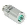 |
Thorlabs' High Quality Triplet Fiber Collimation packages use air-spaced triplet lenses that offer superior beam quality performance when compared to aspheric lens collimators. The benefits of the low-aberration triplet design include an M2 term closer to 1 (Gaussian), less divergence, and less wavefront error. |
| Achromatic Collimators for Multimode Fiber | 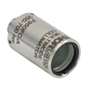 |
Thorlabs' High-NA Achromatic Collimators pair a meniscus lens with an achromatic doublet for high performance across the visible to near-infrared spectrum with low spherical aberration. Designed for use with high-NA multimode fiber, these collimators are ideal for Optogenetics and Fiber Photometry applications. |
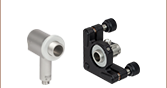
| Reflective Collimators | 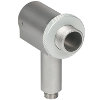 |
Thorlabs' metallic-coated Reflective Collimators are based on a 90° off-axis parabolic mirror. Mirrors, unlike lenses, have a focal length that remains constant over a broad wavelength range. Due to this intrinsic property, a parabolic mirror collimator does not need to be adjusted to accommodate various wavelengths of light, making them ideal for use with polychromatic light. Our fixed reflective collimators are recommended for collimating single and multimode fiber and coupling into multimode fiber. These collimators are available with UV-enhanced aluminum or protected silver reflective coatings and with FC/PC, FC/APC, or SMA connector compatibility. |
| Compact Reflective Collimators | 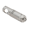 |
Thorlabs' Compact Reflective Collimators incorporate a 90° off-axis parabolic mirror with a protected silver coating. Because the focal length is independent of wavelength for an off-axis parabolic mirror, they are ideal for use with polychromatic light. Our fixed reflective collimators are recommended for collimating single and multimode fiber and coupling into multimode fiber. These collimators are directly compatible with our 16 mm cage system. They are available with FC/PC, FC/APC, or SMA connector inputs. |
| Adjustable Reflective Collimators |  |
Thorlabs' Adjustable Focus Reflective Collimators use a 90° off-axis parabolic (OAP) mirror with a protected silver coating to collimate light from a fiber or couple light into a fiber. The adjustable fiber-to-OAP distance, combined with the OAP having a constant focal length across wavelengths, makes these collimators ideal for optimizing collimation or coupling of polychromatic light with single mode or multimode fiber. These adjustable collimators have a 15.0 mm or 33.0 mm reflected focal length and are available with FC/PC, FC/APC, or SMA connectors. |
| FiberPorts | 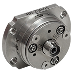 |
These compact, ultra-stable FiberPort micropositioners provide an easy-to-use, stable platform for coupling light into and out of FC/PC, FC/APC, or SMA terminated optical fibers. It can be used with single mode, multimode, or PM fibers and can be mounted onto a post, stage, platform, or laser. The built-in aspheric or achromatic lens is available with five different AR coatings and has five degrees of alignment adjustment (3 translational and 2 pitch). The compact size and long-term alignment stability make the FiberPort an ideal solution for fiber coupling, collimation, or incorporation into OEM systems. |
| Adjustable Fiber Collimators |  |
These collimators are designed to connect onto the end of an FC/PC, FC/APC, or SMA connector and contain an AR-coated aspheric lens. The distance between the aspheric lens and the tip of the fiber can be adjusted to compensate for focal length changes or to recollimate the beam at the wavelength and distance of interest. |
| Achromatic Fiber Collimators with Adjustable Focus |  |
Thorlabs' Achromatic Fiber Collimators with Adjustable Focus are designed with an effective focal length (EFL) of 20 mm, 40 mm, or 80 mm, have optical elements broadband AR coated for one of three wavelength ranges, and are available with FC/PC, FC/APC, or SMA905 connectors. A four-element, air-spaced lens design produces superior beam quality (M2 close to 1) and less wavefront error when compared to aspheric lens collimators. These collimators can be used for free-space coupling into a fiber, collimation of output from a fiber, or in pairs for collimator-to-collimator coupling over long distances, which allows the beam to be manipulated prior to entering the second collimator. |
| Zoom Fiber Collimators |  |
These collimators provide a variable focal length between 6 and 18 mm, while maintaining the collimation of the beam. As a result, the size of the beam can be changed without altering the collimation. This universal device saves time previously spent searching for the best suited fixed fiber collimator and has a very broad range of applications. They are offered with FC/PC, FC/APC, or SMA905 connectors with three different antireflection wavelength ranges to choose from. |
| Single Mode Pigtailed Collimators |  |
Our single mode pigtailed collimators come with one meter of fiber, consist of an AR-coated aspheric lens pre-aligned with respect to a fiber, and are collimated at one of eight wavelengths: 532 nm, 633 nm, 780 nm, 850 nm, 1030 nm, 1064 nm, 1310 nm, or 1550 nm. Although it is possible to use the collimator at any wavelength within the coating range, the coupling loss will increase as the wavelength is detuned from the design wavelength. |
| Polarization Maintaining Pigtailed Collimators | 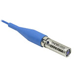 |
Our polarization maintaining pigtailed collimators come with one meter of fiber, consist of an AR-coated aspheric lens pre-aligned with respect to a fiber, and are collimated at one of five wavelengths: 633 nm, 780 nm, 980 nm, 1064 nm, or 1550 nm. Custom wavelengths and connectors are available as well. A line is engraved along the outside of the housing that is parallel to the fast axis. As such, it can be used as a reference when polarized light is launched accordingly. Although it is possible to use the collimator at any wavelength within the coating range, the coupling loss will increase as the wavelength is detuned from the design wavelength. |
| GRIN Fiber Collimators | 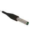 |
Thorlabs offers gradient index (GRIN) fiber collimators that are aligned at a variety of wavelengths from 630 to 1550 nm and have either FC terminated, APC terminated, or unterminated fibers. Our GRIN collimators feature a Ø1.8 mm clear aperture, are AR-coated to ensure low back reflection into the fiber, and are coupled to standard single mode or graded-index multimode fibers. |
| GRIN Lenses |  |
These graded-index (GRIN) lenses are AR coated for applications at 630, 830, 1060, 1300, or 1560 nm that require light to propagate through one fiber, then through a free-space optical system, and finally back into another fiber. They are also useful for coupling light from laser diodes into fibers, coupling the output of a fiber into a detector, or collimating laser light. Our GRIN lenses are designed to be used with our Pigtailed Glass Ferrules and GRIN/Ferrule sleeves. |

 Zoom
Zoom- 2.2 mm Wide Key FC/PC Connector
- Reflected Focal Lengths of 7.0 mm, 15.0 mm, 33.0 mm, or 50.8 mm
- Externally Threaded Aperture: Ø1/2" Lens Tube Compatible (Item Numbers Starting with RC02, RC04, and RC08), or Ø1" Lens Tube Compatible (Item Numbers Starting with RC12)
| Reflective Collimator Specifications | ||||
|---|---|---|---|---|
| Item #a | RFLb | Max Fiber NAc | Typical Collimated Beam Diameter (1/e2)d | Full Angle Beam Divergencee |
| RC02FC-F01 | 7.0 mm | 0.40 | Ø1.5 mm (SM400 at 450 nm) Ø1.3 mm (SM600 at 633 nm) Ø1.5 mm (780HP at 780 nm) Ø1.3 mm (SMF-28-J9 at 1550 nm) Ø2.2 mm (SM1950 at 2 µm) |
0.023° (SM400 at 450 nm) 0.035° (SM600 at 633 nm) 0.037° (780HP at 780 nm) 0.088° (SMF-28-J9 at 1550 nm) 0.067° (SM1950 at 2 µm) |
| RC04FC-F01 | 15.0 mm | 0.30 | Ø3.1 mm (SM400 at 450 nm) Ø2.8 mm (SM600 at 633 nm) Ø3.3 mm (780HP at 780 nm) Ø2.9 mm (SMF-28-J9 at 1550 nm) Ø4.7 mm (SM1950 at 2 µm) |
0.011° (SM400 at 450 nm) 0.016° (SM600 at 633 nm) 0.018° (780HP at 780 nm) 0.040° (SMF-28-J9 at 1550 nm) 0.031° (SM1950 at 2 µm) |
| RC08FC-F01 | 33.0 mm | 0.15 | Ø6.8 mm (SM400 at 450 nm) Ø6.2 mm (SM600 at 633 nm) Ø7.2 mm (780HP at 780 nm) Ø6.3 mm (SMF-28-J9 at 1550 nm) Ø10.2 mm (SM1950 at 2 µm) |
0.005° (SM400 at 450 nm) 0.007° (SM600 at 633 nm) 0.008° (780HP at 780 nm) 0.018° (SMF-28-J9 at 1550 nm) 0.014° (SM1950 at 2 µm) |
| RC12FC-F01 | 50.8 mm | 0.19 | Ø10.5 mm (SM400 at 450 nm) Ø9.5 mm (SM600 at 633 nm) Ø11.0 mm (780HP at 780 nm) Ø9.6 mm (SMF-28-J9 at 1550 nm) Ø15.8 mm (SM1950 at 2 µm) |
0.003° (SM400 at 450 nm) 0.005° (SM600 at 633 nm) 0.005° (780HP at 780 nm) 0.012° (SMF-28-J9 at 1550 nm) 0.009° (SM1950 at 2 µm) |

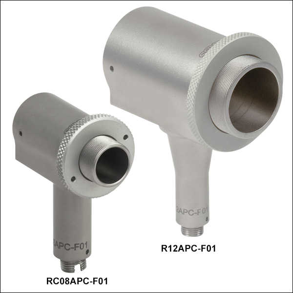 Zoom
Zoom- 2.2 mm Wide Key FC/APC Connector
- Reflected Focal Lengths of 7.0 mm, 15.0 mm, 33.0 mm, or 50.8 mm
- Externally Threaded Aperture: Ø1/2" Lens Tube Compatible (Item Numbers Starting with RC02, RC04, and RC08), or Ø1" Lens Tube Compatible (Item Numbers Starting with RC12)
| Reflective Collimator Specifications | ||||
|---|---|---|---|---|
| Item #a | RFLb | Max Fiber NAc | Typical Collimated Beam Diameter (1/e2)d | Full Angle Beam Divergencee |
| RC02APC-F01 | 7.0 mm | 0.40 | Ø1.5 mm (SM400 at 450 nm) Ø1.3 mm (SM600 at 633 nm) Ø1.5 mm (780HP at 780 nm) Ø1.3 mm (SMF-28-J9 at 1550 nm) Ø2.2 mm (SM1950 at 2 µm) |
0.023° (SM400 at 450 nm) 0.035° (SM600 at 633 nm) 0.037° (780HP at 780 nm) 0.088° (SMF-28-J9 at 1550 nm) 0.067° (SM1950 at 2 µm) |
| RC04APC-F01 | 15.0 mm | 0.30 | Ø3.1 mm (SM400 at 450 nm) Ø2.8 mm (SM600 at 633 nm) Ø3.3 mm (780HP at 780 nm) Ø2.9 mm (SMF-28-J9 at 1550 nm) Ø4.7 mm (SM1950 at 2 µm) |
0.011° (SM400 at 450 nm) 0.016° (SM600 at 633 nm) 0.018° (780HP at 780 nm) 0.040° (SMF-28-J9 at 1550 nm) 0.031° (SM1950 at 2 µm) |
| RC08APC-F01 | 33.0 mm | 0.15 | Ø6.8 mm (SM400 at 450 nm) Ø6.2 mm (SM600 at 633 nm) Ø7.2 mm (780HP at 780 nm) Ø6.3 mm (SMF-28-J9 at 1550 nm) Ø10.2 mm (SM1950 at 2 µm) |
0.005° (SM400 at 450 nm) 0.007° (SM600 at 633 nm) 0.008° (780HP at 780 nm) 0.018° (SMF-28-J9 at 1550 nm) 0.014° (SM1950 at 2 µm) |
| RC12APC-F01 | 50.8 mm | 0.19 | Ø10.5 mm (SM400 at 450 nm) Ø9.5 mm (SM600 at 633 nm) Ø11.0 mm (780HP at 780 nm) Ø9.6 mm (SMF-28-J9 at 1550 nm) Ø15.8 mm (SM1950 at 2 µm) |
0.003° (SM400 at 450 nm) 0.005° (SM600 at 633 nm) 0.005° (780HP at 780 nm) 0.012° (SMF-28-J9 at 1550 nm) 0.009° (SM1950 at 2 µm) |

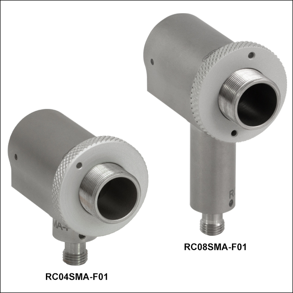 Zoom
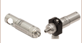
Zoom- SMA Connectors Ideal for Multimode Fiber
- Reflected Focal Lengths of 7.0 mm, 15.0 mm, 33.0 mm, or 50.8 mm
- Externally Threaded Aperture: Ø1/2" Lens Tube Compatible (Item Numbers Starting with RC02, RC04, and RC08), or Ø1" Lens Tube Compatible (Item Numbers Starting with RC12)
| Reflective Collimator Specifications | ||||
|---|---|---|---|---|
| Item #a | RFLb | Max Fiber NAc | Typical Collimated Beam Diameter (1/e2)d | Full Angle Beam Divergencee |
| RC02SMA-F01 | 7.0 mm | 0.40 | Ø1.5 mm (SM400 at 450 nm) Ø1.3 mm (SM600 at 633 nm) Ø1.5 mm (780HP at 780 nm) Ø1.3 mm (SMF-28-J9 at 1550 nm) Ø2.2 mm (SM1950 at 2 µm) |
0.023° (SM400 at 450 nm) 0.035° (SM600 at 633 nm) 0.037° (780HP at 780 nm) 0.088° (SMF-28-J9 at 1550 nm) 0.067° (SM1950 at 2 µm) |
| RC04SMA-F01 | 15.0 mm | 0.30 | Ø3.1 mm (SM400 at 450 nm) Ø2.8 mm (SM600 at 633 nm) Ø3.3 mm (780HP at 780 nm) Ø2.9 mm (SMF-28-J9 at 1550 nm) Ø4.7 mm (SM1950 at 2 µm) |
0.011° (SM400 at 450 nm) 0.016° (SM600 at 633 nm) 0.018° (780HP at 780 nm) 0.040° (SMF-28-J9 at 1550 nm) 0.031° (SM1950 at 2 µm) |
| RC08SMA-F01 | 33.0 mm | 0.15 | Ø6.8 mm (SM400 at 450 nm) Ø6.2 mm (SM600 at 633 nm) Ø7.2 mm (780HP at 780 nm) Ø6.3 mm (SMF-28-J9 at 1550 nm) Ø10.2 mm (SM1950 at 2 µm) |
0.005° (SM400 at 450 nm) 0.007° (SM600 at 633 nm) 0.008° (780HP at 780 nm) 0.018° (SMF-28-J9 at 1550 nm) 0.014° (SM1950 at 2 µm) |
| RC12SMA-F01 | 50.8 mm | 0.19 | Ø10.5 mm (SM400 at 450 nm) Ø9.5 mm (SM600 at 633 nm) Ø11.0 mm (780HP at 780 nm) Ø9.6 mm (SMF-28-J9 at 1550 nm) Ø15.8 mm (SM1950 at 2 µm) |
0.003° (SM400 at 450 nm) 0.005° (SM600 at 633 nm) 0.005° (780HP at 780 nm) 0.012° (SMF-28-J9 at 1550 nm) 0.009° (SM1950 at 2 µm) |