 Products Home / Lasers / Coherent Sources / Laser Diodes by Wavelength / UV Laser Diode: 375 nm Center Wavelength
UV Laser Diode: 375 nm Center Wavelength
- Output Power of 70 mW
- Ø5.6 mm Diode with F Pin Code
Application Idea
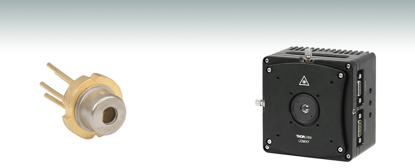
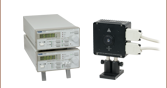
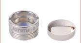
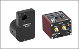
Laser Diode Secured in
LDM56F Temperature-Controlled Mount
(Shown with Collimating Aspheric Lens
Mounted in LDMXY Flexure Adapter)
L375P70MLD
70 mW Output Power


Please Wait
| Laser Diode Selection Guidea |
|---|
| Shop by Wavelength |
| UV (375 nm) Visible (404 nm - 690 nm) NIR (705 nm - 2000 nm) MIR (4.05 µm - 11.00 µm) |
| Shop by Package / Type |
| Webpage Features | |
|---|---|
| Clicking this icon opens a window that contains specifications and mechanical drawings. | |
 |
Clicking this icon allows you to download our standard support documentation. |
Features
- Output Power of 70 mW
- 375 nm Center Wavelength
- Ø5.6 mm TO Can Package
- Compatible with Thorlabs' Laser Diode and TEC Controllers
This web page contains Thorlabs' UV laser diode with a center wavelength at 375 nm. The table below lists basic specifications. The blue Info button next to the part number within the table opens a pop-up window, which contains in-depth information regarding the diode. We recommend our LDM56F(/M) TEC-cooled mount for driving this diode.
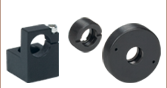
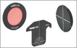
We have categorized the pin configuration of TO-packaged diodes into standard A, B, C, D, E, F, G and H pin codes (see image below). This pin code allows the user to easily determine compatible mounts. TO can diodes are widely supported by our product line.
While the center wavelength is listed for the diode, this is only a typical number. The center wavelength of a particular diode varies from production run to production run, thus the diode you receive may not operate at the typical center wavelength. Diodes can be temperature tuned, which will alter the lasing wavelength.
Please see our Laser Diode Tutorial for more information on laser diodes in general.
Laser diodes are sensitive to electrostatic discharge (ESD). Please take the proper precautions when handling the device; see ESD protection accessories. Our L375P70MLD laser diode contains a Zener diode that can help prevent electrostatic damage. Fabry-Perot lasers are also sensitive to optical feedback, which can cause significant fluctuations in the output power of the laser diode depending on the application. Members of our Technical support staff are available to help you select a laser diode and to discuss possible operation issues.
Choosing a Collimation Lens for Your Laser Diode
Since the output of a laser diode is highly divergent, collimating optics are necessary. Aspheric lenses do not introduce spherical aberration and are therefore are commonly chosen when the collimated laser beam is to be between one and five millimeters. A simple example will illustrate the key specifications to consider when choosing the correct lens for a given application. The second example below is an extension of the procedure, which will show how to circularize an elliptical beam.
Example 1: Collimating a Diverging Beam
- Laser Diode to be Used: L780P010
- Desired Collimated Beam Diameter: Ø3 mm (Major Axis)
When choosing a collimation lens, it is essential to know the divergence angle of the source being used and the desired output diameter. The specifications for the L780P010 laser diode indicate that the typical parallel and perpendicular FWHM beam divergences are 8° and 30°, respectively. Therefore, as the light diverges, an elliptical beam will result. To collect as much light as possible during the collimation process, consider the larger of these two divergence angles in any calculations (i.e., in this case, use 30°). If you wish to convert your elliptical beam into a round one, we suggest using an anamorphic prism pair, which magnifies one axis of your beam; for details, see Example 2 below.
Assuming that the thickness of the lens is small compared to the radius of curvature, the thin lens approximation can be used to determine the appropriate focal length for the asphere. Assuming a divergence angle of 30° (FWHM) and desired beam diameter of 3 mm:
 |
 |
||
| Θ = Divergence Angle | Ø = Beam Diameter | f = Focal Length | r = Collimated Beam Radius = Ø/2 |
Note that the focal length is generally not equal to the needed distance between the light source and the lens.
With this information known, it is now time to choose the appropriate collimating lens. Thorlabs offers a large selection of aspheric lenses. For this application, the ideal lens is a molded glass aspheric lens with focal length near 5.6 mm and our -B antireflection coating, which covers 780 nm. The C171TMD-B (mounted) or 354171-B (unmounted) aspheric lenses have a focal length of 6.20 mm, which will result in a collimated beam diameter (major axis) of 3.3 mm. Next, check to see if the numerical aperture (NA) of the diode is smaller than the NA of the lens:
0.30 = NALens > NADiode ≈ sin(15°) = 0.26
Up to this point, we have been using the full-width at half maximum (FWHM) beam diameter to characterize the beam. However, a better practice is to use the 1/e2 beam diameter. For a Gaussian beam profile, the 1/e2 diameter is almost equal to 1.7X the FWHM diameter. The 1/e2 beam diameter therefore captures more of the laser diode's output light (for greater power delivery) and minimizes far-field diffraction (by clipping less of the incident light).
A good rule of thumb is to pick a lens with an NA twice that of the laser diode NA. For example, either the A390-B or the A390TM-B could be used as these lenses each have an NA of 0.53, which is more than twice the approximate NA of our laser diode (0.26). These lenses each have a focal length of 4.6 mm, resulting in an approximate major beam diameter of 2.5 mm. In general, using a collimating lens with a short focal length will result in a small collimated beam diameter and a large beam divergence, while a lens with a large focal length will result in a large collimated beam diameter and a small divergence.
Example 2: Circularizing an Elliptical Beam
Using the laser diode and aspheric lens chosen above, we can use an anamorphic prism pair to convert our collimated, elliptical beam into a circular beam.
Whereas earlier we considered only the larger divergence angle, we now look at the smaller beam divergence of 8°. From this, and using the effective focal length of the A390-B aspheric lens chosen in Example 1, we can determine the length of the semi-minor axis of the elliptical beam after collimation:
r' = f * tan(Θ'/2) = 4.6 mm * tan(4°) = 0.32 mm
The minor beam diameter is double the semi-minor axis, or 0.64 mm. In order to magnify the minor diameter to be equal to the major diameter of 2.5 mm, we will need an anamorphic prism pair that yields a magnification of 3.9. Thorlabs offers both mounted and unmounted prism pairs. Mounted prism pairs provide the benefit of a stable housing to preserve alignment, while unmounted prism pairs can be positioned at any angle to achieve the exact desired magnification.
The PS883-B mounted prism pair provides a magnification of 4.0 for a 950 nm wavelength beam. Because shorter wavelengths undergo greater magnification when passing through the prism pair, we can expect our 780 nm beam to be magnified by slightly more than 4.0X. Thus, the beam will still maintain a small degree of ellipticity.
Alternatively, we can use the PS871-B unmounted prism pair to achieve the precise magnification of the minor diameter necessary to produce a circular beam. Using the data available here, we see that the PS871-B achieves a magnification of 4.0 when the prisms are positioned at the following angles for a 670 nm wavelength beam:
| α1: +34.608° | α2: -1.2455° |
Refer to the diagram to the right for α1 and α2 definitions. Our 780 nm laser will experience slightly less magnification than a 670 nm beam passing through the prisms at these angles. Some trial and error may be required to achieve the exact desired magnification. In general:
- To increase magnification, rotate the first prism clockwise (increasing α1) and rotate the second prism counterclockwise (decreasing α2).
- To reduce magnification, rotate the first prism counterclockwise (decreasing α1) and rotate the second prism clockwise (increasing α2).
Video Insight: Setting Up a TO Can Laser Diode
Installing a TO can laser diode in a mount and setting it up to run under temperature and current control presents many opportunities to make a mistake that could damage or destroy the laser. This step-by-step guide includes tips for keeping humans and laser diodes safe from harm.
When operated within their specifications, laser diodes have extremely long lifetimes. Most failures occur from mishandling or operating the lasers beyond their maximum ratings. Laser diodes are among the most static-sensitive devices currently made and proper ESD protection should be worn whenever handling a laser diode. Due to their extreme electrostatic sensitivity, laser diodes cannot be returned after their sealed package has been opened. Laser diodes in their original sealed package can be returned for a full refund or credit.
Handling and Storage Precautions
Because of their extreme susceptibility to damage from electrostatic discharge (ESD), care should be taken whenever handling and operating laser diodes.
Wrist Straps
Use grounded anti-static wrist straps whenever handling diodes.
Anti-Static Mats
Always work on grounded anti-static mats.
Laser Diode Storage
When not in use, short the leads of the laser together to protect against ESD damage.
Operating and Safety Precautions
Use an Appropriate Driver
Laser diodes require precise control of operating current and voltage to avoid overdriving the laser. In addition, the laser driver should provide protection against power supply transients. Select a laser driver appropriate for your application. Do not use a voltage supply with a current-limiting resistor since it does not provide sufficient regulation to protect the laser diode.
Power Meters
When setting up and calibrating a laser diode with its driver, use a NIST-traceable power meter to precisely measure the laser output. It is usually safest to measure the laser diode output directly before placing the laser in an optical system. If this is not possible, be sure to take all optical losses (transmissive, aperture stopping, etc.) into consideration when determining the total output of the laser.
Reflections
Flat surfaces in the optical system in front of a laser diode can cause some of the laser energy to reflect back onto the laser’s monitor photodiode, giving an erroneously high photodiode current. If optical components are moved within the system and energy is no longer reflected onto the monitor photodiode, a constant-power feedback loop will sense the drop in photodiode current and try to compensate by increasing the laser drive current and possibly overdriving the laser. Back reflections can also cause other malfunctions or damage to laser diodes. To avoid this, be sure that all surfaces are angled 5-10°, and when necessary, use optical isolators to attenuate direct feedback into the laser.
Heat Sinks
Laser diode lifetime is inversely proportional to operating temperature. Always mount the laser diode in a suitable heat sink to remove excess heat from the laser package.
Voltage and Current Overdrive
Be careful not to exceed the maximum voltage and drive current listed on the specification sheet with each laser diode, even momentarily. Also, reverse voltages as little as 3 V can damage a laser diode.
ESD-Sensitive Device
Laser diodes are susceptible to ESD damage even during operation. This is particularly aggravated by using long interface cables between the laser diode and its driver due to the inductance that the cable presents. Avoid exposing the laser diode or its mounting apparatus to ESD at all times.
ON/OFF and Power-Supply-Coupled Transients
Due to their fast response times, laser diodes can be easily damaged by transients less than 1 µs. High-current devices such as soldering irons, vacuum pumps, and fluorescent lamps can cause large momentary transients, and thus surge-protected outlets should always be used when working with laser diodes.
If you have any questions regarding laser diodes, please contact Thorlabs Technical Support for assistance.
Laser Safety and Classification
Safe practices and proper usage of safety equipment should be taken into consideration when operating lasers. The eye is susceptible to injury, even from very low levels of laser light. Thorlabs offers a range of laser safety accessories that can be used to reduce the risk of accidents or injuries. Laser emission in the visible and near infrared spectral ranges has the greatest potential for retinal injury, as the cornea and lens are transparent to those wavelengths, and the lens can focus the laser energy onto the retina.
 |
 |
 |
 |
 |
 |
 |
 |
 |
Safe Practices and Light Safety Accessories
- Laser safety eyewear must be worn whenever working with Class 3 or 4 lasers.
- Regardless of laser class, Thorlabs recommends the use of laser safety eyewear whenever working with laser beams with non-negligible powers, since metallic tools such as screwdrivers can accidentally redirect a beam.
- Laser goggles designed for specific wavelengths should be clearly available near laser setups to protect the wearer from unintentional laser reflections.
- Goggles are marked with the wavelength range over which protection is afforded and the minimum optical density within that range.
- Laser Safety Curtains and Laser Safety Fabric shield other parts of the lab from high energy lasers.
- Blackout Materials can prevent direct or reflected light from leaving the experimental setup area.
- Thorlabs' Enclosure Systems can be used to contain optical setups to isolate or minimize laser hazards.
- A fiber-pigtailed laser should always be turned off before connecting it to or disconnecting it from another fiber, especially when the laser is at power levels above 10 mW.
- All beams should be terminated at the edge of the table, and laboratory doors should be closed whenever a laser is in use.
- Do not place laser beams at eye level.
- Carry out experiments on an optical table such that all laser beams travel horizontally.
- Remove unnecessary reflective items such as reflective jewelry (e.g., rings, watches, etc.) while working near the beam path.
- Be aware that lenses and other optical devices may reflect a portion of the incident beam from the front or rear surface.
- Operate a laser at the minimum power necessary for any operation.
- If possible, reduce the output power of a laser during alignment procedures.
- Use beam shutters and filters to reduce the beam power.
- Post appropriate warning signs or labels near laser setups or rooms.
- Use a laser sign with a lightbox if operating Class 3R or 4 lasers (i.e., lasers requiring the use of a safety interlock).
- Do not use Laser Viewing Cards in place of a proper Beam Trap.
Laser Classification
Lasers are categorized into different classes according to their ability to cause eye and other damage. The International Electrotechnical Commission (IEC) is a global organization that prepares and publishes international standards for all electrical, electronic, and related technologies. The IEC document 60825-1 outlines the safety of laser products. A description of each class of laser is given below:
| Class | Description | Warning Label |
|---|---|---|
| 1 | This class of laser is safe under all conditions of normal use, including use with optical instruments for intrabeam viewing. Lasers in this class do not emit radiation at levels that may cause injury during normal operation, and therefore the maximum permissible exposure (MPE) cannot be exceeded. Class 1 lasers can also include enclosed, high-power lasers where exposure to the radiation is not possible without opening or shutting down the laser. |  |
| 1M | Class 1M lasers are safe except when used in conjunction with optical components such as telescopes and microscopes. Lasers belonging to this class emit large-diameter or divergent beams, and the MPE cannot normally be exceeded unless focusing or imaging optics are used to narrow the beam. However, if the beam is refocused, the hazard may be increased and the class may be changed accordingly. |  |
| 2 | Class 2 lasers, which are limited to 1 mW of visible continuous-wave radiation, are safe because the blink reflex will limit the exposure in the eye to 0.25 seconds. This category only applies to visible radiation (400 - 700 nm). |  |
| 2M | Because of the blink reflex, this class of laser is classified as safe as long as the beam is not viewed through optical instruments. This laser class also applies to larger-diameter or diverging laser beams. |  |
| 3R | Class 3R lasers produce visible and invisible light that is hazardous under direct and specular-reflection viewing conditions. Eye injuries may occur if you directly view the beam, especially when using optical instruments. Lasers in this class are considered safe as long as they are handled with restricted beam viewing. The MPE can be exceeded with this class of laser; however, this presents a low risk level to injury. Visible, continuous-wave lasers in this class are limited to 5 mW of output power. |  |
| 3B | Class 3B lasers are hazardous to the eye if exposed directly. Diffuse reflections are usually not harmful, but may be when using higher-power Class 3B lasers. Safe handling of devices in this class includes wearing protective eyewear where direct viewing of the laser beam may occur. Lasers of this class must be equipped with a key switch and a safety interlock; moreover, laser safety signs should be used, such that the laser cannot be used without the safety light turning on. Laser products with power output near the upper range of Class 3B may also cause skin burns. |  |
| 4 | This class of laser may cause damage to the skin, and also to the eye, even from the viewing of diffuse reflections. These hazards may also apply to indirect or non-specular reflections of the beam, even from apparently matte surfaces. Great care must be taken when handling these lasers. They also represent a fire risk, because they may ignite combustible material. Class 4 lasers must be equipped with a key switch and a safety interlock. |  |
| All class 2 lasers (and higher) must display, in addition to the corresponding sign above, this triangular warning sign. |  |
|
| Posted Comments: | |
jesus Mendoza
(posted 2019-07-29 04:38:55.233) Can L375P70MLD be couple directly to SMF? YLohia
(posted 2019-08-28 10:07:53.0) Hello, thank you for contacting Thorlabs. Unfortunately, we are unable to pigtail this particular laser diode into a single mode fiber at the moment. |
| The rows shaded green below denote single-frequency lasers. |
| Item # | Wavelength | Output Power | Operating Current | Operating Voltage | Beam Divergence | Laser Mode | Package | |
|---|---|---|---|---|---|---|---|---|
| Parallel | Perpendicular | |||||||
| L375P70MLD | 375 nm | 70 mW | 110 mA | 5.4 V | 9° | 22.5° | Single Transverse Mode | Ø5.6 mm |
| L404P400M | 404 nm | 400 mW | 370 mA | 4.9 V | 13° (1/e2) | 42° (1/e2) | Multimode | Ø5.6 mm |
| LP405-SF10 | 405 nm | 10 mW | 50 mA | 5.0 V | - | - | Single Transverse Mode | Ø5.6 mm, SM Pigtail |
| L405P20 | 405 nm | 20 mW | 38 mA | 4.8 V | 8.5° | 19° | Single Transverse Mode | Ø5.6 mm |
| LP405C1 | 405 nm | 30 mW | 75 mA | 4.3 V | 1.4 mrad | 1.4 mrad | Single Transverse Mode | Ø3.8 mm, SM Pigtail with Collimator |
| L405G2 | 405 nm | 35 mW | 50 mA | 4.9 V | 10° | 21° | Single Transverse Mode | Ø3.8 mm |
| DL5146-101S | 405 nm | 40 mW | 70 mA | 5.2 V | 8° | 19° | Single Transverse Mode | Ø5.6 mm |
| L405A1 | 405 nm | 175 mW (Min) | 150 mA | 5.0 V | 9° | 20° | Single Transverse Mode | Ø5.6 mm |
| LP405-MF300 | 405 nm | 300 mW | 350 mA | 4.5 V | - | - | Multimode | Ø5.6 mm, MM Pigtail |
| L405G1 | 405 nm | 1000 mW | 900 mA | 5.0 V | 13° | 45° | Multimode | Ø9 mm |
| LP450-SF25 | 450 nm | 25 mW | 75 mA | 5.0 V | - | - | Single Transverse Mode | Ø5.6 mm, SM Pigtail |
| L450G3 | 450 nm | 100 mW (Min) | 80 mA | 5.2 V | 8.4° | 21.5° | Single Transverse Mode | Ø3.8 mm |
| L450G2 | 450 nm | 100 mW (Min) | 80 mA | 5.0 V | 8.4° | 21.5° | Single Transverse Mode | Ø5.6 mm |
| L450P1600MM | 450 nm | 1600 mW | 1200 mA | 4.8 V | 7° | 19 - 27° | Multimode | Ø5.6 mm |
| L473P100 | 473 nm | 100 mW | 120 mA | 5.7 V | 10 | 24 | Single Transverse Mode | Ø5.6 mm |
| LP488-SF20 | 488 nm | 20 mW | 70 mA | 6.0 V | - | - | Single Transverse Mode | Ø5.6 mm, SM Pigtail |
| LP488-SF20G | 488 nm | 20 mW | 80 mA | 5.5 V | - | - | Single Transverse Mode | Ø5.6 mm, SM Pigtail |
| L488P60 | 488 nm | 60 mW | 75 mA | 6.8 V | 7° | 23° | Single Transverse Mode | Ø5.6 mm |
| LP515-SF3 | 515 nm | 3 mW | 50 mA | 5.3 V | - | - | Single Transverse Mode | Ø5.6 mm, SM Pigtail |
| L515A1 | 515 nm | 10 mW | 50 mA | 5.4 V | 6.5° | 21° | Single Transverse Mode | Ø5.6 mm |
| LP520-SF15A | 520 nm | 15 mW | 100 mA | 7.0 V | - | - | Single Transverse Mode | Ø5.6 mm, SM Pigtail |
| LP520-SF15 | 520 nm | 15 mW | 140 mA | 6.5 V | - | - | Single Transverse Mode | Ø9 mm, SM Pigtail |
| L520A1 | 520 nm | 30 mW (Min) | 80 mA | 5.5 V | 8° | 22° | Single Transverse Mode | Ø5.6 mm |
| PL520 | 520 nm | 50 mW | 250 mA | 7.0 V | 7° | 22° | Single Transverse Mode | Ø3.8 mm |
| L520P50 | 520 nm | 45 mW | 150 mA | 7.0 V | 7° | 22° | Single Transverse Mode | Ø5.6 mm |
| L520A2 | 520 nm | 110 mW (Min) | 225 mA | 5.9 V | 8° | 22° | Single Transverse Mode | Ø5.6 mm |
| DJ532-10 | 532 nm | 10 mW | 220 mA | 1.9 V | 0.69° | 0.69° | Single Transverse Mode | Ø9.5 mm (non-standard) |
| DJ532-40 | 532 nm | 40 mW | 330 mA | 1.9 V | 0.69° | 0.69° | Single Transverse Mode | Ø9.5 mm (non-standard) |
| LP633-SF50 | 633 nm | 50 mW | 170 mA | 2.6 V | - | - | Single Transverse Mode | Ø5.6 mm, SM Pigtail |
| HL63163DG | 633 nm | 100 mW | 170 mA | 2.6 V | 8.5° | 18° | Single Transverse Mode | Ø5.6 mm |
| LPS-635-FC | 635 nm | 2.5 mW | 70 mA | 2.2 V | - | - | Single Transverse Mode | Ø9 mm, SM Pigtail |
| LPS-PM635-FC | 635 nm | 2.5 mW | 60 mA | 2.2 V | - | - | Single Transverse Mode | Ø9.0 mm, PM Pigtail |
| L635P5 | 635 nm | 5 mW | 30 mA | <2.7 V | 8° | 32° | Single Transverse Mode | Ø5.6 mm |
| HL6312G | 635 nm | 5 mW | 50 mA | <2.7 V | 8° | 31° | Single Transverse Mode | Ø9 mm |
| LPM-635-SMA | 635 nm | 8 mW | 50 mA | 2.2 V | - | - | Multimode | Ø9 mm, MM Pigtail |
| LP635-SF8 | 635 nm | 8 mW | 60 mA | 2.3 V | - | - | Single Transverse Mode | Ø5.6 mm, SM Pigtail |
| HL6320G | 635 nm | 10 mW | 60 mA | 2.2 V | 8° | 31° | Single Transverse Mode | Ø9 mm |
| HL6322G | 635 nm | 15 mW | 75 mA | 2.4 V | 8° | 30° | Single Transverse Mode | Ø9 mm |
| L637P5 | 637 nm | 5 mW | 20 mA | <2.4 V | 8° | 34° | Single Transverse Mode | Ø5.6 mm |
| LP637-SF50 | 637 nm | 50 mW | 140 mA | 2.6 V | - | - | Single Transverse Mode | Ø5.6 mm, SM Pigtail |
| LP637-SF70 | 637 nm | 70 mW | 220 mA | 2.7 V | - | - | Single Transverse Mode | Ø5.6 mm, SM Pigtail |
| HL63142DG | 637 nm | 100 mW | 140 mA | 2.7 V | 8° | 18° | Single Transverse Mode | Ø5.6 mm |
| HL63133DG | 637 nm | 170 mW | 250 mA | 2.8 V | 9° | 17° | Single Transverse Mode | Ø5.6 mm |
| HL6388MG | 637 nm | 250 mW | 340 mA | 2.3 V | 10° | 40° | Multimode | Ø5.6 mm |
| L637G1 | 637 nm | 1200 mW | 1100 mA | 2.5 V | 10° | 32° | Multimode | Ø9 mm (non-standard) |
| L638P040 | 638 nm | 40 mW | 92 mA | 2.4 V | 10° | 21° | Single Transverse Mode | Ø5.6 mm |
| L638P150 | 638 nm | 150 mW | 230 mA | 2.7 V | 9 | 18 | Single Transverse Mode | Ø3.8 mm |
| L638P200 | 638 nm | 200 mW | 280 mA | 2.9 V | 8 | 14 | Single Transverse Mode | Ø5.6 mm |
| L638P700M | 638 nm | 700 mW | 820 mA | 2.2 V | 9° | 35° | Multimode | Ø5.6 mm |
| HL6358MG | 639 nm | 10 mW | 40 mA | 2.4 V | 8° | 21° | Single Transverse Mode | Ø5.6 mm |
| HL6323MG | 639 nm | 30 mW | 100 mA | 2.5 V | 8.5° | 30° | Single Transverse Mode | Ø5.6 mm |
| HL6362MG | 640 nm | 40 mW | 90 mA | 2.5 V | 10° | 21° | Single Transverse Mode | Ø5.6 mm |
| LP642-SF20 | 642 nm | 20 mW | 90 mA | 2.5 V | - | - | Single Transverse Mode | Ø5.6 mm, SM Pigtail |
| LP642-PF20 | 642 nm | 20 mW | 110 mA | 2.5 V | - | - | Single Transverse Mode | Ø5.6 mm, PM Pigtail |
| HL6364DG | 642 nm | 60 mW | 120 mA | 2.5 V | 10° | 21° | Single Transverse Mode | Ø5.6 mm |
| HL6366DG | 642 nm | 80 mW | 150 mA | 2.5 V | 10° | 21° | Single Transverse Mode | Ø5.6 mm |
| HL6385DG | 642 nm | 150 mW | 250 mA | 2.6 V | 9° | 17° | Single Transverse Mode | Ø5.6 mm |
| L650P007 | 650 nm | 7 mW | 28 mA | 2.2 V | 9° | 28° | Single Transverse Mode | Ø5.6 mm |
| LPS-660-FC | 658 nm | 7.5 mW | 65 mA | 2.6 V | - | - | Single Transverse Mode | Ø5.6 mm, SM Pigtail |
| LP660-SF20 | 658 nm | 20 mW | 80 mA | 2.6 V | - | - | Single Transverse Mode | Ø5.6 mm, SM Pigtail |
| LPM-660-SMA | 658 nm | 22.5 mW | 65 mA | 2.6 V | - | - | Multimode | Ø5.6 mm, MM Pigtail |
| HL6501MG | 658 nm | 30 mW | 75 mA | 2.6 V | 8.5° | 22° | Single Transverse Mode | Ø5.6 mm |
| L658P040 | 658 nm | 40 mW | 75 mA | 2.2 V | 10° | 20° | Single Transverse Mode | Ø5.6 mm |
| LP660-SF40 | 658 nm | 40 mW | 135 mA | 2.5 V | - | - | Single Transverse Mode | Ø5.6 mm, SM Pigtail |
| LP660-SF60 | 658 nm | 60 mW | 210 mA | 2.4 V | - | - | Single Transverse Mode | Ø5.6 mm, SM Pigtail |
| HL6544FM | 660 nm | 50 mW | 115 mA | 2.3 V | 10° | 17° | Single Transverse Mode | Ø5.6 mm |
| LP660-SF50 | 660 nm | 50 mW | 140 mA | 2.3 V | - | - | Single Transverse Mode | Ø5.6 mm, SM Pigtail |
| HL6545MG | 660 nm | 120 mW | 170 mA | 2.45 V | 10° | 17° | Single Transverse Mode | Ø5.6 mm |
| L660P120 | 660 nm | 120 mW | 175 mA | 2.5 V | 10° | 17° | Single Transverse Mode | Ø5.6 mm |
| L670VH1 | 670 nm | 1 mW | 2.5 mA | 2.6 V | 10° | 10° | Single Transverse Mode | TO-46 |
| LPS-675-FC | 670 nm | 2.5 mW | 55 mA | 2.2 V | - | - | Single Transverse Mode | Ø9 mm, SM Pigtail |
| HL6748MG | 670 nm | 10 mW | 30 mA | 2.2 V | 8° | 25° | Single Transverse Mode | Ø5.6 mm |
| HL6714G | 670 nm | 10 mW | 55 mA | <2.7 V | 8° | 22° | Single Transverse Mode | Ø9 mm |
| HL6756MG | 670 nm | 15 mW | 35 mA | 2.3 V | 8° | 24° | Single Transverse Mode | Ø5.6 mm |
| LP685-SF15 | 685 nm | 15 mW | 55 mA | 2.1 V | - | - | Single Transverse Mode | Ø5.6 mm, SM Pigtail |
| HL6750MG | 685 nm | 50 mW | 70 mA | 2.3 V | 9° | 21° | Single Transverse Mode | Ø5.6 mm |
| HL6738MG | 690 nm | 30 mW | 85 mA | 2.5 V | 8.5° | 19° | Single Transverse Mode | Ø5.6 mm |
| LP705-SF15 | 705 nm | 15 mW | 55 mA | 2.3 V | - | - | Single Transverse Mode | Ø5.6 mm, SM Pigtail |
| HL7001MG | 705 nm | 40 mW | 75 mA | 2.5 V | 9° | 18° | Single Transverse Mode | Ø5.6 mm |
| LP730-SF15 | 730 nm | 15 mW | 70 mA | 2.5 V | - | - | Single Transverse Mode | Ø5.6 mm, SM Pigtail |
| HL7302MG | 730 nm | 40 mW | 75 mA | 2.5 V | 9° | 18° | Single Transverse Mode | Ø5.6 mm |
| L760VH1 | 760 nm | 0.5 mW | 3 mA (Max) | 2.2 V | 12° | 12° | Single Frequency | TO-46 |
| DBR760PN | 761 nm | 9 mW | 125 mA | 2.0 V | - | - | Single Frequency | Butterfly, PM Pigtail |
| L763VH1 | 763 nm | 0.5 mW | 3 mA (Max) | 2.0 V | 10° | 10° | Single Frequency | TO-46 |
| DBR767PN | 767 nm | 23 mW | 220 mA | 1.87 V | - | - | Single Frequency | Butterfly, PM Pigtail |
| DBR770PN | 770 nm | 35 mW | 220 mA | 1.92 V | - | - | Single Frequency | Butterfly, PM Pigtail |
| L780P010 | 780 nm | 10 mW | 24 mA | 1.8 V | 8° | 30° | Single Transverse Mode | Ø5.6 mm |
| LP780-SAD15 | 780 nm | 15 mW | 180 mA | 2.2 V | - | - | Single Frequency | Ø9 mm, SM Pigtail |
| DBR780PN | 780 nm | 45 mW | 250 mA | 1.9 V | - | - | Single Frequency | Butterfly, PM Pigtail |
| L785P5 | 785 nm | 5 mW | 28 mA | 1.9 V | 10° | 29° | Single Transverse Mode | Ø5.6 mm |
| LPS-PM785-FC | 785 nm | 6.5 mW | 60 mA | - | - | - | Single Transverse Mode | Ø5.6 mm, PM Pigtail |
| LPS-785-FC | 785 nm | 10 mW | 65 mA | 1.85 V | - | - | Single Transverse Mode | Ø5.6 mm, SM Pigtail |
| LP785-SF20 | 785 nm | 20 mW | 85 mA | 1.9 V | - | - | Single Transverse Mode | Ø5.6 mm, SM Pigtail |
| DBR785S | 785 nm | 25 mW | 230 mA | 2.0 V | - | - | Single Frequency | Butterfly, SM Pigtail |
| DBR785P | 785 nm | 25 mW | 230 mA | 2.0 V | - | - | Single Frequency | Butterfly, PM Pigtail |
| L785P25 | 785 nm | 25 mW | 45 mA | 1.9 V | 8° | 30° | Single Transverse Mode | Ø5.6 mm |
| FPV785S | 785 nm | 50 mW | 410 mA | 2.2 V | - | - | Single Frequency | Butterfly, SM Pigtail |
| FPV785P | 785 nm | 50 mW | 410 mA | 2.1 V | - | - | Single Frequency | Butterfly, PM Pigtail |
| LP785-SAV50 | 785 nm | 50 mW | 500 mA | 2.2 V | - | - | Single Frequency | Ø9 mm, SM Pigtail |
| L785P090 | 785 nm | 90 mW | 125 mA | 2.0 V | 10° | 17° | Single Transverse Mode | Ø5.6 mm |
| LP785-SF100 | 785 nm | 100 mW | 300 mA | 2.0 V | - | - | Single Transverse Mode | Ø9 mm, SM Pigtail |
| FPL785P | 785 nm | 200 mW | 500 mA | 2.1 V | - | - | Single Transverse Mode | Butterfly, PM Pigtail |
| FPL785S-250 | 785 nm | 250 mW (Min) | 500 mA | 2.0 V | - | - | Single Transverse Mode | Butterfly, SM Pigtail |
| LD785-SEV300 | 785 nm | 300 mW | 500 mA (Max) | 2.0 V | 8° | 16° | Single Frequency | Ø9 mm |
| LD785-SH300 | 785 nm | 300 mW | 400 mA | 2.0 V | 7° | 18° | Single Transverse Mode | Ø9 mm |
| FPL785C | 785 nm | 300 mW | 400 mA | 2.0 V | 7° | 18° | Single Transverse Mode | 3 mm x 5 mm Submount |
| LD785-SE400 | 785 nm | 400 mW | 550 mA | 2.0 V | 7° | 16° | Single Transverse Mode | Ø9 mm |
| FPV785M | 785 nm | 600 mW | 1100 mA | 1.9 V | - | - | Multimode | Butterfly, MM Pigtail |
| L795VH1 | 795 nm | 0.25 mW | 1.2 mA | 1.8 V | 20° | 12° | Single Frequency | TO-46 |
| DBR795PN | 795 nm | 40 mW | 230 mA | 2.0 V | - | - | Single Frequency | Butterfly, PM Pigtail |
| DBR808PN | 808 nm | 42 mW | 250 mA | 2 V | - | - | Single Frequency | Butterfly, PM Pigtail |
| LP808-SA60 | 808 nm | 60 mW | 150 mA | 1.9 V | - | - | Single Transverse Mode | Ø9 mm, SM Pigtail |
| M9-808-0150 | 808 nm | 150 mW | 180 mA | 1.9 V | 8° | 17° | Single Transverse Mode | Ø9 mm |
| L808P200 | 808 nm | 200 mW | 260 mA | 2 V | 10° | 30° | Multimode | Ø5.6 mm |
| FPL808P | 808 nm | 200 mW | 600 mA | 2.1 V | - | - | Single Transverse Mode | Butterfly, PM Pigtail |
| FPL808S | 808 nm | 200 mW | 750 mA | 2.3 V | - | - | Single Transverse Mode | Butterfly, SM Pigtail |
| L808H1 | 808 nm | 300 mW | 400 mA | 2.1 V | 14° | 6° | Single Transverse Mode | Ø9 mm |
| LD808-SE500 | 808 nm | 500 mW | 750 mA | 2.2 V | 7° | 14° | Single Transverse Mode | Ø9 mm |
| LD808-SEV500 | 808 nm | 500 mW | 800 mA (Max) | 2.2 V | 8° | 14° | Single Frequency | Ø9 mm |
| L808P500MM | 808 nm | 500 mW | 650 mA | 1.8 V | 12° | 30° | Multimode | Ø5.6 mm |
| L808P1000MM | 808 nm | 1000 mW | 1100 mA | 2 V | 9° | 30° | Multimode | Ø9 mm |
| DBR816PN | 816 nm | 45 mW | 250 mA | 1.95 V | - | - | Single Frequency | Butterfly, PM Pigtail |
| LP820-SF80 | 820 nm | 80 mW | 230 mA | 2.3 V | - | - | Single Transverse Mode | Ø5.6 mm, SM Pigtail |
| L820P100 | 820 nm | 100 mW | 145 mA | 2.1 V | 9° | 17° | Single Transverse Mode | Ø5.6 mm |
| L820P200 | 820 nm | 200 mW | 250 mA | 2.4 V | 9° | 17° | Single Transverse Mode | Ø5.6 mm |
| DBR828PN | 828 nm | 24 mW | 250 mA | 2.0 V | - | - | Single Frequency | Butterfly, PM Pigtail |
| LPS-830-FC | 830 nm | 10 mW | 120 mA | - | - | - | Single Transverse Mode | Ø5.6 mm, SM Pigtail |
| LPS-PM830-FC | 830 nm | 10 mW | 50 mA | 2.0 V | - | - | Single Transverse Mode | Ø5.6 mm, PM Pigtail |
| LP830-SF30 | 830 nm | 30 mW | 115 mA | 1.9 V | - | - | Single Transverse Mode | Ø9 mm, SM Pigtail |
| HL8338MG | 830 nm | 50 mW | 75 mA | 1.9 V | 9° | 22° | Single Transverse Mode | Ø5.6 mm |
| L830H1 | 830 nm | 250 mW | 3 A (Max) | 2 V | 8° | 10° | Single Transverse Mode | Ø9 mm |
| FPL830P | 830 nm | 300 mW | 900 mA | 2.22 V | - | - | Single Transverse Mode | Butterfly, PM Pigtail |
| FPL830S | 830 nm | 350 mW | 900 mA | 2.5 V | - | - | Single Transverse Mode | Butterfly, SM Pigtail |
| LD830-SE650 | 830 nm | 650 mW | 900 mA | 2.3 V | 7° | 13° | Single Transverse Mode | Ø9 mm |
| LD830-MA1W | 830 nm | 1 W | 2 A | 2.1 V | 7° | 24° | Multimode | Ø9 mm |
| LD830-ME2W | 830 nm | 2 W | 3 A (Max) | 2.0 V | 8° | 21° | Multimode | Ø9 mm |
| L840P200 | 840 nm | 200 mW | 255 mA | 2.4 V | 9 | 17 | Single Transverse Mode | Ø5.6 mm |
| L850VH1 | 850 nm | 1 mW | 6 mA (Max) | 2 V | 12° | 12° | Single Frequency | TO-46 |
| L850P010 | 850 nm | 10 mW | 50 mA | 2 V | 10° | 30° | Single Transverse Mode | Ø5.6 mm |
| L850P030 | 850 nm | 30 mW | 65 mA | 2 V | 8.5° | 30° | Single Transverse Mode | Ø5.6 mm |
| FPV852S | 852 nm | 20 mW | 400 mA | 2.2 V | - | - | Single Frequency | Butterfly, SM Pigtail |
| FPV852P | 852 nm | 20 mW | 400 mA | 2.2 V | - | - | Single Frequency | Butterfly, PM Pigtail |
| DBR852PN | 852 nm | 24 mW | 300 mA | 2.0 V | - | - | Single Frequency | Butterfly, PM Pigtail |
| LP852-SF30 | 852 nm | 30 mW | 115 mA | 1.9 V | - | - | Single Transverse Mode | Ø9 mm, SM Pigtail |
| L852P50 | 852 nm | 50 mW | 75 mA | 1.9 V | 9° | 22° | Single Transverse Mode | Ø5.6 mm |
| LP852-SF60 | 852 nm | 60 mW | 150 mA | 2.0 V | - | - | Single Transverse Mode | Ø9 mm, SM Pigtail |
| L852P100 | 852 nm | 100 mW | 120 mA | 1.9 V | 8° | 28° | Single Transverse Mode | Ø9 mm |
| L852P150 | 852 nm | 150 mW | 170 mA | 1.9 V | 8° | 18° | Single Transverse Mode | Ø9 mm |
| L852SEV1 | 852 nm | 270 mW | 400 mA (Max) | 2.0 V | 9° | 12° | Single Frequency | Ø9 mm |
| L852H1 | 852 nm | 300 mW | 415 mA (Max) | 2 V | 7° | 15° | Single Transverse Mode | Ø9 mm |
| FPL852P | 852 nm | 300 mW | 900 mA | 2.35 V | - | - | Single Transverse Mode | Butterfly, PM Pigtail |
| FPL852S | 852 nm | 350 mW | 900 mA | 2.5 V | - | - | Single Transverse Mode | Butterfly, SM Pigtail |
| LD852-SE600 | 852 nm | 600 mW | 950 mA | 2.3 V | 7° (1/e2) | 13° (1/e2) | Single Transverse Mode | Ø9 mm |
| LD852-SEV600 | 852 nm | 600 mW | 1050 mA (Max) | 2.2 V | 8° | 13° (1/e2) | Single Frequency | Ø9 mm |
| LP880-SF3 | 880 nm | 3 mW | 25 mA | 2.2 V | - | - | Single Transverse Mode | Ø5.6 mm, SM Pigtail |
| L880P010 | 880 nm | 10 mW | 30 mA | 2.0 V | 12° | 37° | Single Transverse Mode | Ø5.6 mm |
| L895VH1 | 895 nm | 0.2 mW | 1.4 mA | 1.6 V | 20° | 13° | Single Frequency | TO-46 |
| DBR895PN | 895 nm | 12 mW | 300 mA | 2 V | - | - | Single Frequency | Butterfly, PM Pigtail |
| LP904-SF3 | 904 nm | 3 mW | 30 mA | 1.5 V | - | - | Single Transverse Mode | Ø5.6 mm, SM Pigtail |
| L904P010 | 904 nm | 10 mW | 50 mA | 2.0 V | 10° | 30° | Single Transverse Mode | Ø5.6 mm |
| LP915-SF40 | 915 nm | 40 mW | 130 mA | 1.5 V | - | - | Single Transverse Mode | Ø9 mm, SM Pigtail |
| DBR935PN | 935 nm | 13 mW | 300 mA | 1.75 V | - | - | Single Frequency | Butterfly, PM Pigtail |
| LP940-SF30 | 940 nm | 30 mW | 90 mA | 1.5 V | - | - | Single Transverse Mode | Ø9 mm, SM Pigtail |
| M9-940-0200 | 940 nm | 200 mW | 270 mA | 1.9 V | 8° | 28° | Single Transverse Mode | Ø9 mm |
| L960H1 | 960 nm | 250 mW | 400 mA | 2.1 V | 11° | 12° | Single Transverse Mode | Ø9 mm |
| FPV976S | 976 nm | 30 mW | 400 mA (Max) | 2.2 V | - | - | Single Frequency | Butterfly, SM Pigtail |
| FPV976P | 976 nm | 30 mW | 400 mA (Max) | 2.2 V | - | - | Single Frequency | Butterfly, PM Pigtail |
| DBR976PN | 976 nm | 33 mW | 450 mA | 2.0 V | - | - | Single Frequency | Butterfly, PM Pigtail |
| L976SEV1 | 976 nm | 270 mW | 400 mA (Max) | 2.0 V | 9° | 12° | Single Frequency | Ø9 mm |
| BL976-SAG3 | 976 nm | 300 mW | 470 mA | 2.0 V | - | - | Single Transverse Mode | Butterfly, SM Pigtail |
| BL976-PAG500 | 976 nm | 500 mW | 830 mA | 2.0 V | - | - | Single Transverse Mode | Butterfly, PM Pigtail |
| BL976-PAG700 | 976 nm | 700 mW | 1090 mA | 2.0 V | - | - | Single Transverse Mode | Butterfly, PM Pigtail |
| BL976-PAG900 | 976 nm | 900 mW | 1480 mA | 2.5 V | - | - | Single Transverse Mode | Butterfly, PM Pigtail |
| L980P010 | 980 nm | 10 mW | 25 mA | 2 V | 10° | 30° | Single Transverse Mode | Ø5.6 mm |
| LP980-SF15 | 980 nm | 15 mW | 70 mA | 1.5 V | - | - | Single Transverse Mode | Ø5.6 mm, SM Pigtail |
| L980P030 | 980 nm | 30 mW | 50 mA | 1.5 V | 10° | 35° | Single Transverse Mode | Ø5.6 mm |
| L980P100A | 980 nm | 100 mW | 150 mA | 1.6 V | 6° | 32° | Multimode | Ø5.6 mm |
| LP980-SA60 | 980 nm | 60 mW | 230 mA | 2.0 V | - | - | Single Transverse Mode | Ø9.0 mm, SM Pigtail |
| LP980-SA100 | 980 nm | 100 mW | 180 mA | 1.5 V | - | - | Single Transverse Mode | Ø5.6 mm, SM Pigtail |
| L980H1 | 980 nm | 200 mW | 300 mA (Max) | 2.0 V | 8° | 13° | Single Transverse Mode | Ø9 mm |
| L980P200 | 980 nm | 200 mW | 300 mA | 1.5 V | 6° | 30° | Multimode | Ø5.6 mm |
| DBR1060SN | 1060 nm | 130 mW | 650 mA | 2.0 V | - | - | Single Frequency | Butterfly, SM Pigtail |
| DBR1060PN | 1060 nm | 130 mW | 650 mA | 1.8 V | - | - | Single Frequency | Butterfly, PM Pigtail |
| DBR1064S | 1064 nm | 40 mW | 150 mA | 2.0 V | - | - | Single Frequency | Butterfly, SM Pigtail |
| DBR1064P | 1064 nm | 40 mW | 150 mA | 2.0 V | - | - | Single Frequency | Butterfly, PM Pigtail |
| DBR1064PN | 1064 nm | 110 mW | 550 mA | 2.0 V | - | - | Single Frequency | Butterfly, PM Pigtail |
| LPS-1060-FC | 1064 nm | 50 mW | 220 mA | 1.4 V | - | - | Single Transverse Mode | Ø9 mm, SM Pigtail |
| M9-A64-0200 | 1064 nm | 200 mW | 280 mA | 1.7 V | 8° | 28° | Single Transverse Mode | Ø9 mm |
| L1064H1 | 1064 nm | 300 mW | 700 mA | 1.92 V | 7.6° | 13.5° | Single Transverse Mode | Ø9 mm |
| L1064H2 | 1064 nm | 450 mW | 1100 mA | 1.92 V | 7.6° | 13.5° | Single Transverse Mode | Ø9 mm |
| DBR1083PN | 1083 nm | 100 mW | 500 mA | 1.75 V | - | - | Single Frequency | Butterfly, PM Pigtail |
| L1270P5DFB | 1270 nm | 5 mW | 15 mA | 1.1 V | 7° | 9° | Single Frequency | Ø5.6 mm |
| L1290P5DFB | 1290 nm | 5 mW | 16 mA | 1.0 V | 7° | 9° | Single Frequency | Ø5.6 mm |
| LP1310-SAD2 | 1310 nm | 2.0 mW | 40 mA | 1.1 V | - | - | Single Frequency | Ø5.6 mm, SM Pigtail |
| LP1310-PAD2 | 1310 nm | 2.0 mW | 40 mA | 1.0 V | - | - | Single Frequency | Ø5.6 mm, PM Pigtail |
| LPS-PM1310-FC | 1310 nm | 2.5 mW | 20 mA | 1.1 V | - | - | Single Transverse Mode | Ø5.6 mm, PM Pigtail |
| L1310P5DFB | 1310 nm | 5 mW | 16 mA | 1.0 V | 7° | 9° | Single Frequency | Ø5.6 mm |
| ML725B8F | 1310 nm | 5 mW | 20 mA | 1.1 V | 25° | 30° | Single Transverse Mode | Ø5.6 mm |
| LPSC-1310-FC | 1310 nm | 50 mW | 350 mA | 2 V | - | - | Single Transverse Mode | Ø5.6 mm, SM Pigtail |
| FPL1053S | 1310 nm | 130 mW | 400 mA | 1.7 V | - | - | Single Transverse Mode | Butterfly, SM Pigtail |
| FPL1053P | 1310 nm | 130 mW | 400 mA | 1.7 V | - | - | Single Transverse Mode | Butterfly, PM Pigtail |
| FPL1053T | 1310 nm | 300 mW (Pulsed) | 750 mA | 2 V | 15° | 28° | Single Transverse Mode | Ø5.6 mm |
| FPL1053C | 1310 nm | 300 mW (Pulsed) | 750 mA | 2 V | 15° | 27° | Single Transverse Mode | Chip on Submount |
| L1310G1 | 1310 nm | 2000 mW | 5 A | 1.5 V | 7° | 24° | Multimode | Ø9 mm |
| L1330P5DFB | 1330 nm | 5 mW | 14 mA | 1.0 V | 7° | 9° | Single Frequency | Ø5.6 mm |
| L1370G1 | 1370 nm | 2000 mW | 5 A | 1.4 V | 6° | 22° | Multimode | Ø9 mm |
| BL1425-PAG500 | 1425 nm | 500 mW | 1600 mA | 2.0 V | - | - | Single Transverse Mode | Butterfly, PM Pigtail |
| BL1436-PAG500 | 1436 nm | 500 mW | 1600 mA | 2.0 V | - | - | Single Transverse Mode | Butterfly, PM Pigtail |
| L1450G1 | 1450 nm | 2000 mW | 5 A | 1.4 V | 7° | 22° | Multimode | Ø9 mm |
| BL1456-PAG500 | 1456 nm | 500 mW | 1600 mA | 2.0 V | - | - | Single Transverse Mode | Butterfly, PM Pigtail |
| L1470P5DFB | 1470 nm | 5 mW | 19 mA | 1.0 V | 7° | 9° | Single Frequency | Ø5.6 mm |
| L1480G1 | 1480 nm | 2000 mW | 5 A | 1.6 V | 6° | 20° | Multimode | Ø9 mm |
| L1490P5DFB | 1490 nm | 5 mW | 24 mA | 1.0 V | 7° | 9° | Single Frequency | Ø5.6 mm |
| L1510P5DFB | 1510 nm | 5 mW | 20 mA | 1.0 V | 7° | 9° | Single Frequency | Ø5.6 mm |
| L1530P5DFB | 1530 nm | 5 mW | 21 mA | 1.0 V | 7° | 9° | Single Frequency | Ø5.6 mm |
| LPS-1550-FC | 1550 nm | 1.5 mW | 30 mA | 1.0 V | - | - | Single Transverse Mode | Ø5.6 mm, SM Pigtail |
| LPS-PM1550-FC | 1550 nm | 1.5 mW | 30 mA | 1.1 V | - | - | Single Transverse Mode | Ø5.6 mm, SM Pigtail |
| LP1550-SAD2 | 1550 nm | 2.0 mW | 40 mA | 1.0 V | - | - | Single Frequency | Ø5.6 mm, SM Pigtail |
| LP1550-PAD2 | 1550 nm | 2.0 mW | 40 mA | 1.0 V | - | - | Single Frequency | Ø5.6 mm, PM Pigtail |
| L1550P5DFB | 1550 nm | 5 mW | 20 mA | 1.0 V | 8° | 10° | Single Frequency | Ø5.6 mm |
| ML925B45F | 1550 nm | 5 mW | 30 mA | 1.1 V | 25° | 30° | Single Transverse Mode | Ø5.6 mm |
| SFL1550S | 1550 nm | 40 mW | 300 mA | 1.5 V | - | - | Single Frequency | Butterfly, SM Pigtail |
| SFL1550P | 1550 nm | 40 mW | 300 mA | 1.5 V | - | - | Single Frequency | Butterfly, PM Pigtail |
| LPSC-1550-FC | 1550 nm | 50 mW | 250 mA | 2 V | - | - | Single Transverse Mode | Ø5.6 mm, SM Pigtail |
| FPL1009S | 1550 nm | 100 mW | 400 mA | 1.4 V | - | - | Single Transverse Mode | Butterfly, SM Pigtail |
| FPL1009P | 1550 nm | 100 mW | 400 mA | 1.4 V | - | - | Single Transverse Mode | Butterfly, PM Pigtail |
| ULN15PC | 1550 nm | 140 mW | 650 mA | 3.0 V | - | - | Single Frequency | Extended Butterfly, PM Pigtail |
| ULN15PT | 1550 nm | 140 mW | 650 mA | 3.0 V | - | - | Single Frequency | Extended Butterfly, PM Pigtail |
| FPL1001C | 1550 nm | 150 mW | 400 mA | 1.4 V | 18° | 31° | Single Transverse Mode | Chip on Submount |
| FPL1055T | 1550 nm | 300 mW (Pulsed) | 750 mA | 2 V | 15° | 28° | Single Transverse Mode | Ø5.6 mm |
| FPL1055C | 1550 nm | 300 mW (Pulsed) | 750 mA | 2 V | 15° | 28° | Single Transverse Mode | Chip on Submount |
| L1550G1 | 1550 nm | 1700 mW | 5 A | 1.5 V | 7° | 28° | Multimode | Ø9 mm |
| DFB1550 | 1555 nm | 100 mW (Min) | 1000 mA (Max) | 3.0 V | - | - | Single Frequency | Butterfly, SM Pigtail |
| DFB1550N | 1555 nm | 130 mW (Min) | 1800 mA (Max) | 3.0 V | - | - | Single Frequency | Butterfly, SM Pigtail |
| DFB1550P | 1555 nm | 100 mW (Min) | 1000 mA (Max) | 3.0 V | - | - | Single Frequency | Butterfly, PM Pigtail |
| DFB1550PN | 1555 nm | 130 mW (Min) | 1800 mA (Max) | 3.0 V | - | - | Single Frequency | Butterfly, PM Pigtail |
| L1570P5DFB | 1570 nm | 5 mW | 25 mA | 1.0 V | 7° | 9° | Single Frequency | Ø5.6 mm |
| L1575G1 | 1575 nm | 1700 mW | 5 A | 1.5 V | 6° | 28° | Multimode | Ø9 mm |
| LPSC-1625-FC | 1625 nm | 50 mW | 350 mA | 1.5 V | - | - | Single Transverse Mode | Ø5.6 mm, SM Pigtail |
| FPL1054S | 1625 nm | 80 mW | 400 mA | 1.7 V | - | - | Single Transverse Mode | Butterfly, SM Pigtail |
| FPL1054P | 1625 nm | 80 mW | 400 mA | 1.7 V | - | - | Single Transverse Mode | Butterfly, PM Pigtail |
| FPL1054C | 1625 nm | 250 mW (Pulsed) | 750 mA | 2 V | 15° | 28° | Single Transverse Mode | Chip on Submount |
| FPL1054T | 1625 nm | 200 mW (Pulsed) | 750 mA | 2 V | 15° | 28° | Single Transverse Mode | Ø5.6 mm |
| FPL1059S | 1650 nm | 80 mW | 400 mA | 1.7 V | - | - | Single Transverse Mode | Butterfly, SM Pigtail |
| FPL1059P | 1650 nm | 80 mW | 400 mA | 1.7 V | - | - | Single Transverse Mode | Butterfly, PM Pigtail |
| FPL1059C | 1650 nm | 225 mW (Pulsed) | 750 mA | 2 V | 15° | 28° | Single Transverse Mode | Chip on Submount |
| FPL1059T | 1650 nm | 225 mW (Pulsed) | 750 mA | 2 V | 15° | 28° | Single Transverse Mode | Ø5.6 mm |
| FPL1940S | 1940 nm | 15 mW | 400 mA | 2 V | - | - | Single Transverse Mode | Butterfly, SM Pigtail |
| FPL2000S | 2 µm | 15 mW | 400 mA | 2 V | - | - | Single Transverse Mode | Butterfly, SM Pigtail |
| FPL2000C | 2 µm | 30 mW | 400 mA | 5.2 V | 8° | 19° | Single Transverse Mode | Chip on Submount |
| ID3250HHLH | 3.00 - 3.50 µm (DFB) | 5 mW | 400 mA (Max) | 5 V | 6 mrad (0.34°) | 6 mrad (0.34°) | Single Frequency | Two-Tab C-Mount |
| QF3850T1 | 3.85 µm (FP) | 200 mW | 600 mA (Max) | 13.5 V | 30° | 40° | Single Transverse Mode | Ø9 mm |
| QF3850HHLH | 3.85 µm (FP) | 320 mW (Min) | 1100 mA (Max) | 13 V | 6 mrad (0.34°) | 6 mrad (0.34°) | Single Transverse Mode | Horizontal HHL |
| QF4040HHLH | 4.05 µm (FP) | 320 mW (Min) | 1100 mA (Max) | 13 V | 6 mrad (0.34°) | 6 mrad (0.34°) | Single Transverse Mode | Horizontal HHL |
| QD4500CM1 | 4.00 - 5.00 µm (DFB) | 40 mW | 500 mA (Max) | 10.5 V | 30° | 40° | Single Frequency | Two-Tab C-Mount |
| QD4500HHLH | 4.00 - 5.00 µm (DFB) | 80 mW | 500 mA (Max) | 11 V | 6 mrad (0.34°) | 6 mrad (0.34°) | Single Frequency | Horizontal HHL |
| QF4050T2 | 4.05 µm (FP) | 70 mW | 250 mA | 12 V | 30° | 40° | Single Transverse Mode | Ø9 mm |
| QF4050C2 | 4.05 µm (FP) | 300 mW | 400 mA | 12 V | 30 | 42 | Single Transverse Mode | Two-Tab C-Mount |
| QF4050T1 | 4.05 µm (FP) | 300 mW | 600 mA (Max) | 12.0 V | 30° | 40° | Single Transverse Mode | Ø9 mm |
| QF4050D2 | 4.05 µm (FP) | 800 mW | 750 mA | 13 V | 30° | 40° | Single Transverse Mode | D-Mount |
| QF4050D3 | 4.05 µm (FP) | 1200 mW | 1000 mA | 13 V | 30° | 40° | Single Transverse Mode | D-Mount |
| QD4472HH | 4.472 µm (DFB) | 85 mW | 500 mA (Max) | 11 V | 6 mrad (0.34°) | 6 mrad (0.34°) | Single Frequency | Horizontal HHL |
| QF4600T2 | 4.60 µm (FP) | 200 mW | 500 mA (Max) | 13.0 V | 30° | 40° | Single Transverse Mode | Ø9 mm |
| QF4600T1 | 4.60 µm (FP) | 400 mW | 800 mA (Max) | 12.0 V | 30° | 40° | Single Transverse Mode | Ø9 mm |
| QF4600C2 | 4.60 µm (FP) | 600 mW | 600 mA | 12 V | 30° | 42° | Single Transverse Mode | Two-Tab C-Mount |
| QF4600T3 | 4.60 µm (FP) | 1000 mW | 800 mA (Max) | 13 V | 30° | 40° | Single Transverse Mode | Ø9 mm |
| QF4600D4 | 4.60 µm (FP) | 2500 mW | 1800 mA | 12.5 V | 40° | 30° | Single Transverse Mode | D-Mount |
| QF4600D3 | 4.60 µm (FP) | 3000 mW | 1700 mA | 12.5 V | 30° | 40° | Single Transverse Mode | D-Mount |
| QD4602HH | 4.602 µm (DFB) | 150 mW | 1000 mA (Max) | 12 V | 6 mrad (0.34°) | 6 mrad (0.34°) | Single Frequency | Horizontal HHL |
| QF4650HHLH | 4.65 µm (FP) | 1500 mW (Min) | 1100 mA | 12 V | 6 mrad (0.34°) | 6 mrad (0.34°) | Single Transverse Mode | Horizontal HHL |
| QD5500CM1 | 5.00 - 6.00 µm (DFB) | 40 mW | 700 mA (Max) | 9.5 V | 30° | 45° | Single Frequency | Two-Tab C-Mount |
| QD5500HHLH | 5.00 - 6.00 µm (DFB) | 150 mW | 500 mA (Max) | 11 V | 6 mrad (0.34°) | 6 mrad (0.34°) | Single Frequency | Horizontal HHL |
| QD5250C2 | 5.20 - 5.30 µm (DFB) | 60 mW | 700 mA (Max) | 9.5 V | 30° | 45° | Single Frequency | Two-Tab C-Mount |
| QD5263HH | 5.263 µm (DFB) | 130 mW | 1000 mA (Max) | 12 V | 6 mrad (0.34°) | 6 mrad (0.34°) | Single Frequency | Horizontal HHL |
| QD6500CM1 | 6.00 - 7.00 µm (DFB) | 40 mW | 650 mA (Max) | 10 V | 35° | 50° | Single Frequency | Two-Tab C-Mount |
| QD6500HHLH | 6.00 - 7.00 µm (DFB) | 80 mW | 600 mA (Max) | 11 V | 6 mrad (0.34°) | 6 mrad (0.34°) | Single Frequency | Horizontal HHL |
| QD6134HH | 6.134 µm (DFB) | 50 mW | 1000 mA (Max) | 12 V | 6 mrad (0.34°) | 6 mrad (0.34°) | Single Frequency | Horizontal HHL |
| QD7500CM1 | 7.00 - 8.00 µm (DFB) | 40 mW | 600 mA (Max) | 10 V | 40° | 50° | Single Frequency | Two-Tab C-Mount |
| QD7500HHLH | 7.00 - 8.00 µm (DFB) | 50 mW | 700 mA (Max) | 12 V | 6 mrad (0.34°) | 6 mrad (0.34°) | Single Frequency | Horizontal HHL |
| QD7500DM1 | 7.00 - 8.00 µm (DFB) | 100 mW | 600 mA (Max) | 11.5 V | 40° | 55° | Single Frequency | D-Mount |
| QD7416HH | 7.416 µm (DFB) | 100 mW | 1000 mA (Max) | 12 V | 6 mrad (0.34°) | 6 mrad (0.34°) | Single Frequency | Horizontal HHL |
| QD7716HH | 7.716 µm (DFB) | 30 mW | 1000 mA (Max) | 12 V | 6 mrad (0.34°) | 6 mrad (0.34°) | Single Frequency | Horizontal HHL |
| QF7900HB | 7.9 µm (FP) | 700 mW | 1600 mA (Max) | 9 V | 6 mrad (0.34°) | 6 mrad (0.34°) | Single Transverse Mode | Horizontal HHL |
| QD7901HH | 7.901 µm (DFB) | 50 mW | 700 mA (Max) | 10 V | 6 mrad (0.34°) | 6 mrad (0.34°) | Single Frequency | Horizontal HHL |
| QD8050CM1 | 8.00 - 8.10 µm (DFB) | 100 mW | 1000 mA (Max) | 9.5 V | 55° | 70° | Single Frequency | Two-Tab C-Mount |
| QD8500CM1 | 8.00 - 9.00 µm (DFB) | 100 mW | 900 mA (Max) | 9.5 V | 40° | 55° | Single Frequency | Two-Tab C-Mount |
| QD8500HHLH | 8.00 - 9.00 µm (DFB) | 100 mW | 600 mA (Max) | 10.2 V | 6 mrad (0.34°) | 6 mrad (0.34°) | Single Frequency | Horizontal HHL |
| QF8450C2 | 8.45 µm (FP) | 300 mW | 750 mA | 9 V | 40° | 60° | Single Transverse Mode | Two-Tab C-Mount |
| QF8500HB | 8.5 µm (FP) | 500 mW | 2000 mA (Max) | 9 V | 6 mrad (0.34°) | 6 mrad (0.34°) | Single Transverse Mode | Horizontal HHL |
| QD8650CM1 | 8.60 - 8.70 µm (DFB) | 50 mW | 900 mA (Max) | 9.5 V | 55° | 70° | Single Frequency | Two-Tab C-Mount |
| QD8912HH | 8.912 µm (DFB) | 150 mW | 1000 mA (Max) | 12 V | 6 mrad (0.34°) | 6 mrad (0.34°) | Single Frequency | Horizontal HHL |
| QD9500CM1 | 9.00 - 10.00 µm (DFB) | 60 mW | 800 mA (Max) | 9.5 V | 40° | 55° | Single Frequency | Two-Tab C-Mount |
| QD9500HHLH | 9.00 - 10.00 µm (DFB) | 100 mW | 600 mA (Max) | 10.2 V | 6 mrad (0.34°) | 6 mrad (0.34°) | Single Frequency | Horizontal HHL |
| QD9062HH | 9.062 µm (DFB) | 130 mW | 1000 mA (Max) | 12 V | 6 mrad (0.34°) | 6 mrad (0.34°) | Single Frequency | Horizontal HHL |
| QF9150C2 | 9.15 µm (FP) | 200 mW | 850 mA | 11 V | 40° | 60° | Single Transverse Mode | Two-Tab C-Mount |
| QF9200HB | 9.2 µm (FP) | 250 mW | 2000 mA (Max) | 9 V | 6 mrad (0.34°) | 6 mrad (0.34°) | Single Transverse Mode | Horizontal HHL |
| QF9500T1 | 9.5 µm (FP) | 300 mW | 550 mA | 12 V | 40° | 55° | Single Transverse Mode | Ø9 mm |
| QD9550C2 | 9.50 - 9.60 µm (DFB) | 60 mW | 800 mA (Max) | 9.5 V | 40° | 55° | Single Frequency | Two-Tab C-Mount |
| QF9550CM1 | 9.55 µm (FP) | 80 mW | 1500 mA | 7.8 V | 35° | 60° | Single Transverse Mode | Two-Tab C-Mount |
| QD9697HH | 9.697 µm (DFB) | 80 mW | 1000 mA (Max) | 12 V | 6 mrad (0.34°) | 6 mrad (0.34°) | Single Frequency | Horizontal HHL |
| QD10500CM1 | 10.00 - 11.00 µm (DFB) | 40 mW | 600 mA (Max) | 10 V | 40° | 55° | Single Frequency | Two-Tab C-Mount |
| QD10500HHLH | 10.00 - 11.00 µm (DFB) | 50 mW | 700 mA (Max) | 12 V | 6 mrad (0.34°) | 6 mrad (0.34°) | Single Frequency | Horizontal HHL |
| QD10530HH | 10.530 µm (DFB) | 50 mW | 1000 mA (Max) | 12 V | 6 mrad (0.34°) | 6 mrad (0.34°) | Single Frequency | Horizontal HHL |
| QD10549HH | 10.549 µm (DFB) | 60 mW | 1000 mA (Max) | 12 V | 6 mrad (0.34°) | 6 mrad (0.34°) | Single Frequency | Horizontal HHL |
| QD10622HH | 10.622 µm (DFB) | 60 mW | 1000 mA (Max) | 12 V | 6 mrad (0.34°) | 6 mrad (0.34°) | Single Frequency | Horizontal HHL |
| The rows shaded green above denote single-frequency lasers. |