 Products Home / Optomechanical Components / Optical Post Assemblies / Ø1" Optical Post Assemblies / Ø1" Pillar Post Mounts
Ø1" Pillar Post Mounts

- Mount Ø1" (Ø25 mm) Pillar Post Extensions
- Height and Rotational Adjustments
- Flexure Clamping Mechanisms Provide High Clamping Force
BA2F
Flexure Clamping Base
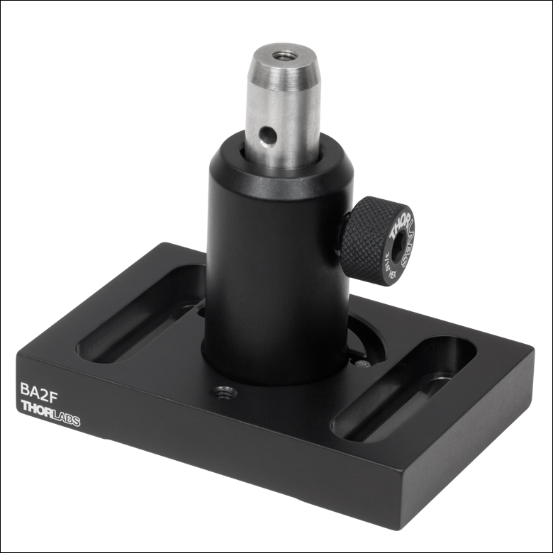
RB2
Adjustable Height Post Base
BA2F Clamping Base Mounting a Ø1" Post (Post Not Included)
RB2 Post Base Mounting a Ø1" Post (Post Not Included)
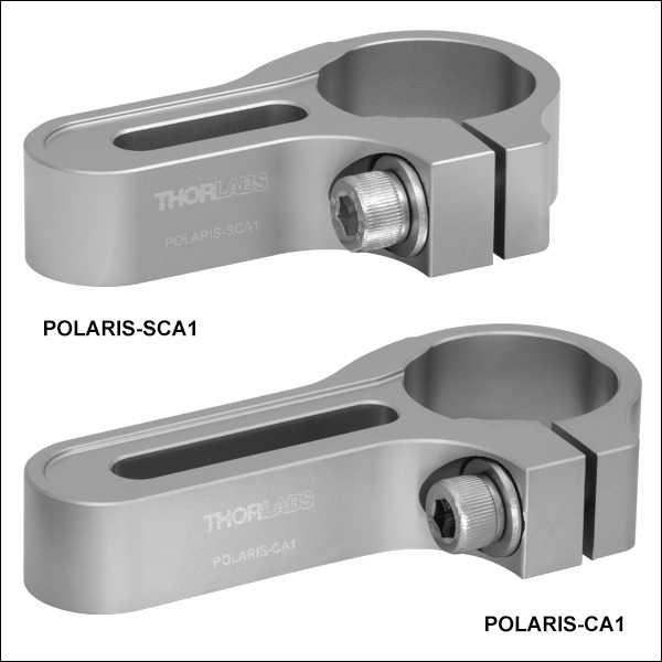
POLARIS-CA1 Clamping Arm Mounting a Polaris Ø1" Monolithic Optic Mount
(Mount and Mirror Not Included)
POLARIS-SCA1
Non-Bridging Clamping Arm
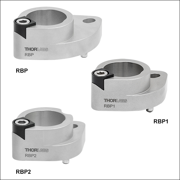
RBP1
Pin-Aligned, Clamping Post Base
RBP1 Post Base Mounting a Ø1" Post (Post Not Included)


Please Wait
Features
- Post Mounts for Ø1" (Ø25 mm) Pillar Post Extensions
- Coarse Height and Rotation Adjustment
- More Mounting Flexibility than Achievable with Direct Table Threading
Thorlabs' Ø1" Post Mounts allow Ø1" (Ø25 mm) Pillar Posts to be secured to an optical table at various heights and angles of rotation. They provide mounting flexibility while remaining stable and secure. Additionally, the BA2F Flexure Clamping Base is compatible with Ø1/2" post holders. The POLARIS-SCA25/M and POLARIS-CA25/M Non-Bridging Clamping Arms can also be used to mount Ø1/2" post holders; however, be sure to not over-torque the arm while the post holder is inserted and to loosen the clamp sufficiently when removing the post holder to prevent damage.
In addition to the post mounts offered here, we also carry Ø1" post holders that mount to an optical table using a clamping fork and offer a larger post height adjustment range.
| Posted Comments: | |
| No Comments Posted |
 Posts")
 Zoom
Zoom
Click to Enlarge
Click for POLARIS-CA1/M Holding Torque Results*
Figure 484A The non-bridging clamping fork design has undergone extensive testing to ensure high-quality performance. See the full presentation for more details.
*It is important to note that the 1/4"-20 and M6 x 1.0 clamping torque values have been adjusted to provide the same clamping post and table forces. Also note that the maximum recommended tightening torque for an 18-8 stainless steel screw is 75.2 in-lbs for a 1/4"-20 screw and 8.8 N-m for an M6 x 1.0 screw. Higher mounting torques can cause the screw to fail.
Click to Enlarge
Figure 484B The arm can be mounted with either flat surface in contact with the table, allowing for compact setups.
Click to Enlarge
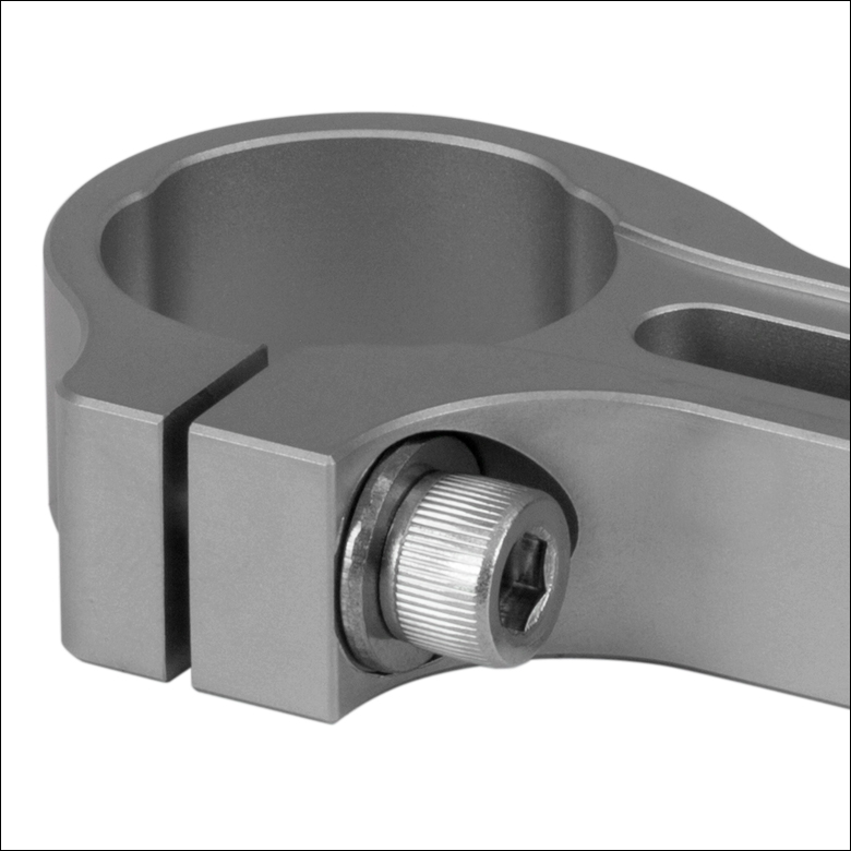
Figure 484C Side-Located 1/4"-20 (M6) Screw Actuates Clamping Bore
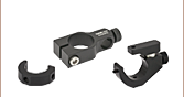
- 3-Point Contact Bore with Flexure Clamping Mechanism
- Versions for Ø1" or Ø25 mm Posts for Polaris Mounts and Ø1" Monolithic Polaris Mount (See Table 484D)
- 0.60" Bore Depth Supports Height Adjustments Up to 0.25"
- Allows Posts to be Rotated 360°
- 0.75" (19.1 mm) or 1.30" (33.0 mm) Slot for 1/4"-20 (M6) Cap Screw
- Heat-Treated, Stress-Relieved Stainless Steel Provides Large Clamping Force
- Design Supports Left- and Right-Handed Orientations (See Figure 484C)
- High Stability Ideal for Use with Our Kinematic Polaris Mirror Mounts
- Vacuum Compatible to 10-9 Torr at 25 °C with Proper Bake Out
- ±0.001" (±0.02 mm) Surface Flatness
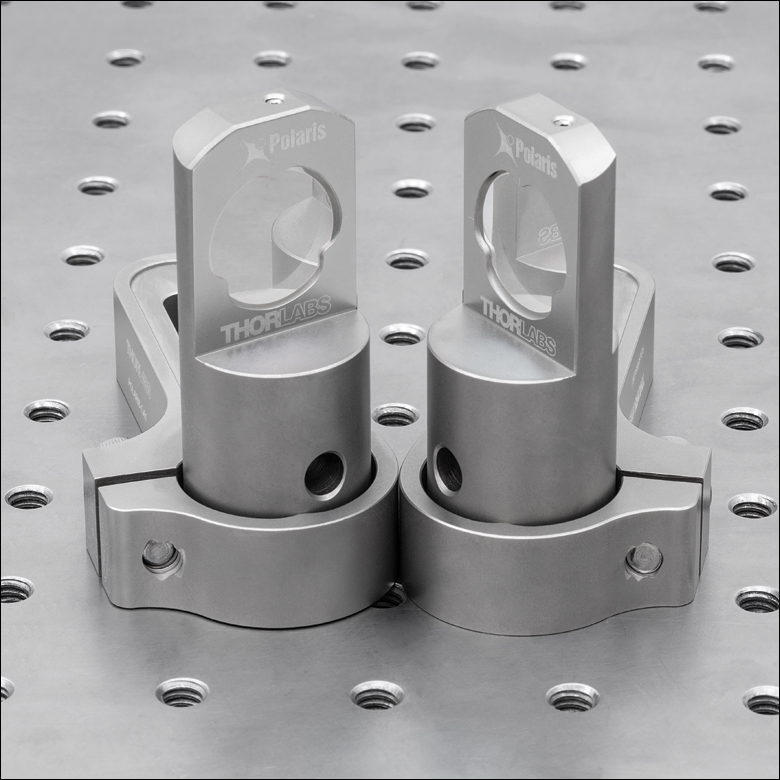
Thorlabs' Non-Bridging Clamping Arms are the ideal solution for stably mounting our Ø1" or Ø25 mm Posts for Polaris Mounts or Ø1" Monolithic Polaris Mount. Each clamping arm, which is machined from heat-treated, stress-relieved stainless steel bar stock, provides extremely high holding forces with minimal torquing of the mounting screws (see Figure 484A).
The flat, non-bridging top and bottom surfaces of each clamping arm allow it to be used with either side in contact with an optical table or other mounting surface. This feature allows the clamp to be positioned in left- or right-handed orientations and optical components to be placed in near contact to one another while minimizing the footprint (see Figure 484B). On each side of the arm, a relief cut around the slot protects the ±0.001" (±0.02 mm) flat surface from any marring due to the screw and washer, allowing for more stable mounting.
The clamping arms are offered with slot lengths of 0.75" (19.1 mm) or 1.30" (33.0 mm), providing flexibility when used in applications such as tight laser cavity setups. Four of our clamping arms are designed to hold Ø1" posts, while the remaining two are designed to hold Ø25 mm posts; see Table 484D for details. Note the arms with a Ø1" (25.4 mm) bore are not compatible with Ø25 mm posts; the bore diameter is too large and will not contact the post when clamping.
Non-Bridging Design: Industry Standard Clamping Fork
vs. Thorlabs' Non-Bridging Clamping Arm
Industry standard clamping forks are designed with a bridge, as shown in Figure 484E, for clamping to pedestal-style posts or post holders. This design will slightly damage the laser platform during each use by pulling up the part of the platform located under the bridge. The Thorlabs clamping arm, as shown in Figure 484F, is designed with a flat top and bottom to eliminate this problem.
 Click to Enlarge
Figure 484E A Bridge is Created When an Industry Standard Clamping Fork is Used with a Pedestal Post
 Click to Enlarge
Figure 484F The Thorlabs Clamping Arm Eliminates the Bridge Created by an Industry Standard Clamping Fork
The flexure clamp, shown in Figure 484C, is actuated using a side-located 1/4"-20 (M6 x 1.0) cap screw and allows a post to be rotated 360° about its center. As the flexure clamp and mounting slot are secured with separate screws, the position of the fork and the rotational alignment of the post can be adjusted independently. While best performance is achieved with full post engagement, the 0.60" (15.2 mm) thick mounting bore supports up to 0.25" of post height adjustment.
The non-bridging clamping arm design has undergone extensive testing to ensure high-quality performance; see Figure 484A. For optimal performance, we recommend tightening the flexure clamping screw of an imperial clamping arm with 15 to 25 in-lb of torque and the flexure clamping screw of a metric clamping arm with 1.75 to 3 N•m of torque. When mounting to a table or platform, we recommend using 40 to 65 in-lb of torque for an imperial clamping arm and 4.75 to 7 N•m of torque for a metric clamping arm. Please note that the values for imperial and metric clamps are not a direct conversion due to an efficiency difference between 1/4"-20 and M6 x 1.0 screws. The efficiency of M6 x 1.0 screws is about 5% less than that of 1/4"-20 screws due to differences in diameter and pitch. For best results, use the maximum recommended torques from each range. These torque values can be dialed in using a torque driver.
| Table 484D Specifications | ||||
|---|---|---|---|---|
| Item # | Compatible Post Size |
Clamping Screw |
Slot Length | Footprint |
| POLARIS-SCA1 | Ø1" (25.4 mm) |
1/4"-20 (3/16" Hex) |
0.75" (19.1 mm) |
2.78" x 1.60" (70.5 mm x 40.6 mm) |
| POLARIS-CA1 | 1.30" (33.0 mm) |
3.33" x 1.60" (84.5 mm x 40.6 mm) |
||
| POLARIS-SCA1/M | M6 x 1.0 (5 mm Hex) |
0.75" (19.1 mm) |
2.78" x 1.60" (70.5 mm x 40.6 mm) |
|
| POLARIS-CA1/M | 1.30" (33.0 mm) |
3.33" x 1.60" (84.5 mm x 40.6 mm) |
||
| POLARIS-SCA25/M | Ø25.0 mm (Ø0.98") |
0.75" (19.1 mm) |
2.78" x 1.60" (70.5 mm x 40.6 mm) |
|
| POLARIS-CA25/M | 1.30" (33.0 mm) |
3.33" x 1.60" (84.5 mm x 40.6 mm) |
||

 Zoom
Zoom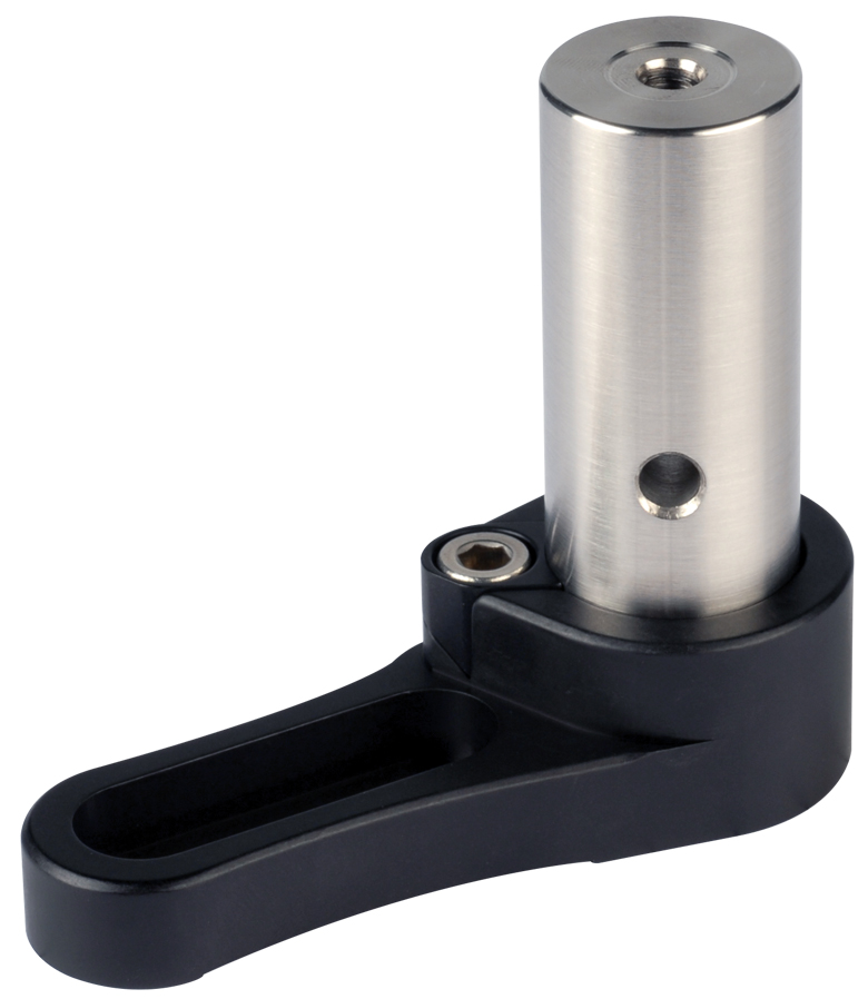
Click to Enlarge
Figure 243A Deep Base Allows Height Adjustment
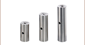
- RB2 Base Allows Post Extensions to be Used as a Variable Height Mounting Structure
- Hollow Base Allows Post Extension to Pass Through for 0.5" of Height Adjustability
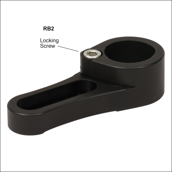
- Convenient Vertically Accessed Locking Screw
The RB2(/M) pillar post base mounts Ø1" (25 mm) optical posts at a variable height (shown in Figure 243A). The hollow base allows the post to pass through, allowing 0.5" of post height adjustment. Translation is locked via a top-located clamping screw.

 Zoom
Zoom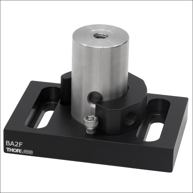
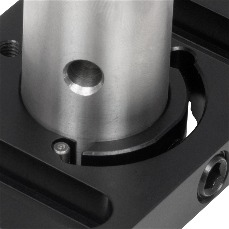
Click to Enlarge
Figure G3.2 An 8-32 tapped hole can be used with a cap screw or setscrew and the RM1B post collar for a coarse rotational and height adjustment stop.
Click to Enlarge
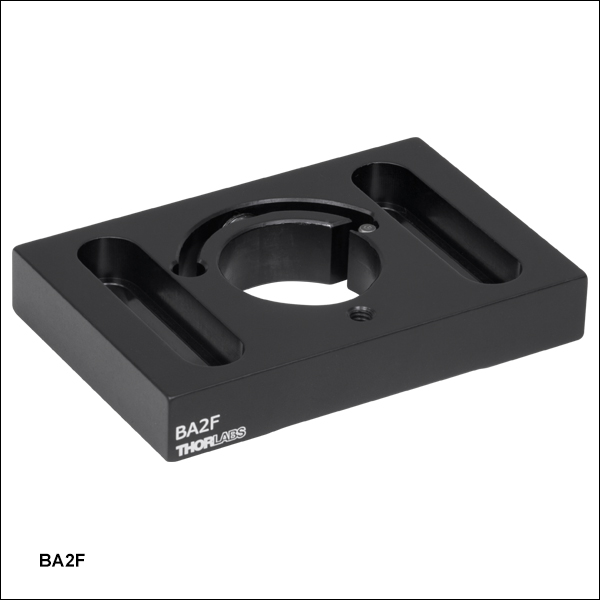
Figure G3.1 The BA2F is compatible with both Ø1/2" post holders (shown here) and Ø1" posts.
Click to Enlarge
Figure G3.3 Steel Insert Prevents Damage to Flexure Mechanism by Limiting Overall Travel
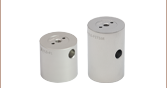
- Post Mount with a Ø1" (Ø25 mm) Double Bore and Flexure Clamping Mechanism
- Mounts Ø1" Posts or Ø1/2" Post Holders
- 0.325" (8.3 mm) of Height Adjustment and 360° Coarse Rotational Adjustment
- 8-32 (M4) Tapped Hole for Rotation Hard Stop with the RM1B Ø1" Post Collar
The BA2F Post Mount features a Ø1" (Ø25 mm) double bore and flexure clamping mechanism. This clamp allows for both height and rotational adjustment of either an Ø1" optical post or a Ø1/2" post holder. The clamping mechanism is actuated by a 3/8"-24 (M10 x 1.5) clamping screw with 3/16" (5 mm) hex key. A permanent steel insert* at the end of the flexing mechanism prevents damage to the clamp from overtightening.
An RM1A or RM1B Ø1" post collar can be used with Ø1" posts or Ø1/2" post holders as a hard stop for repeatable height adjustment. The base also features an 8-32 (M4) tapped hole near the double bore; when a cap screw or setscrew is inserted into this hole, the post collar can also function as a rotational stop (see Figure G3.2).
Each base has two 1.25" (31.8 mm) long counterbored slots for 1/4"-20 (M6) cap screws for attachment to an optical table or breadboard.
*Since our Ø1/2" post holders are slightly smaller in diameter than our Ø1" posts, the flexure mechanism will contact the steel insert when mounting Ø1/2" post holders. This is normal and will not harm the mounting base.

 Zoom
Zoom
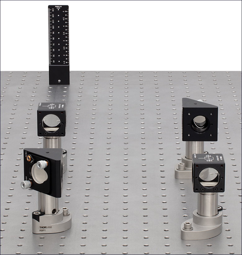
Click to Enlarge Figure 770B A BHM6 ruler is used with RBP1 and RBP post bases to align a Mach-Zehnder interferometer using KCB1 mirror mounts and CCM1-PBS251 cage cube-mounted polarizing beamsplitter cubes.
Click to Enlarge Figure 770A Alignment of Laser Beam Along Holes of Optical Table Using an RBP1 Post Base
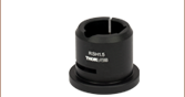
- Ideal for Aligning a Laser Beam Along the Threaded Holes of an Optical Table
- Compatible with Imperial and Metric Optical Tables and Ø1" or Ø25 mm Pillar Posts
- Alignment Pins and Attachment Screw Position the Reflective Surface of an Optic in a Compatible Mount Above a Hole in the Table:
- RBP(/M): Compatible with Mounts with a Post-Centered Reflective Optical Surface
- RBP1(/M): Compatible with KCB1 Series Mounts (Except Item # KCB1P(/M))
- RBP2(/M): Compatible with KCB2 Series Mounts
- Post Rotates Freely When Locking Screw is Loosened
Thorlabs' Pin-Aligned, Clamping Post Bases are designed to simplify aligning a laser beam over the threaded holes in an imperial or metric optical table by holding the reflective surface of a mirror or other reflective optic mounted in a compatible mount above a hole in the table (see Figure 770A). The RBP(/M) base is designed to be used with a kinematic mount with a post-centered front plate or a cube mount that centers the reflective surface of the mounted optic above the hole in the optical post. The RBP1(/M) and RBP2(/M) bases are compatible with KCB1 Series Right-Angle Kinematic Mounts (except Item # KCB1P(/M)) or KCB2 Series Right-Angle Kinematic Mounts, respectively. Please see Table 770C for a list of compatible mounts for each post base.
| Table 770C RBPx(/M) Post Base Selection Guide | |
|---|---|
| Item # | Compatible Mounts |
| RBP(/M) | KM05CP(/M), KM100CP(/M), and KM200CP(/M) Kinematic Mirror Mounts |
| Kinematic Mirror Mounts with Centering Plates: KM05(/M) with KCP05(/M), KM100 with KCP1(/M), and KM200 with KCP2(/M) |
|
| 16 mm Cage Cubes, 30 mm Cage Cubes, and 60 mm Cage Cubes with a Centered 8-32 (M4 x 0.7) or 1/4"-20 (M6 x 1.0) Mounting Hole | |
| RBP1(/M) | KCB1(/M), KCB1C(/M), KCB1E(/M), and KCB1EC(/M) Right-Angle Kinematic Mirror Mounts |
| RBP2(/M) | KCB2(/M), KCB2C(/M),and KCB2EC(/M) Right-Angle Kinematic Mirror Mounts |
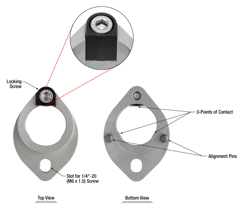
Click to Enlarge
Figure 770D Top and Bottom View of the RBP1 Post Base
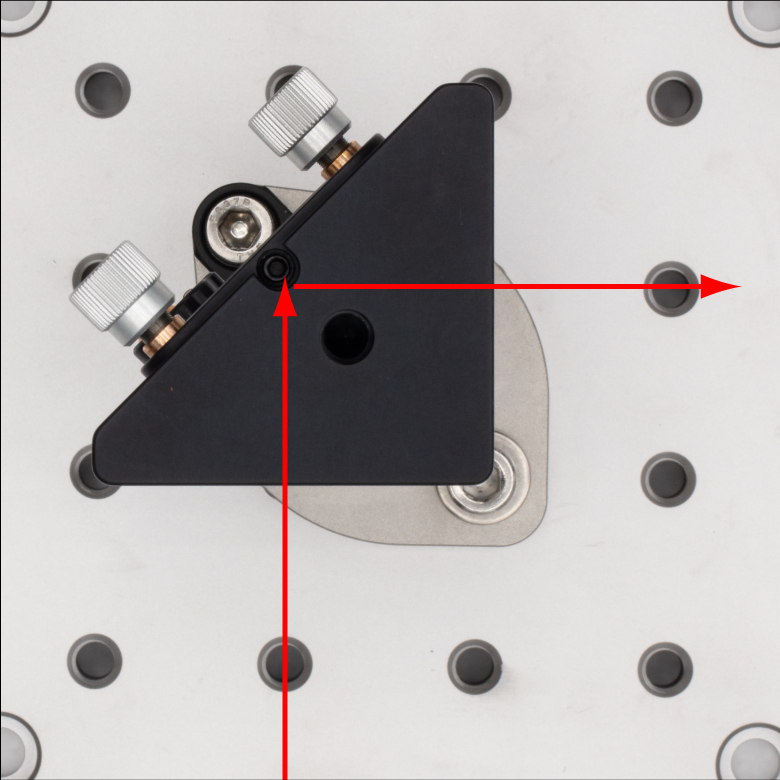
These post bases accept Ø1" (Ø25 mm) Pillar Posts, to which the compatible mount can be connected, as shown in Figure 770B; note that the bases do not accept pedestal posts. Alignment pins on the bottom of these post bases fit into the holes on an optical table, which sets the mount in the correct position, and a 1/4"-20 (M6 x 1.0) cap screw and washer (not included) can be used to secure the post base to the table. The body of the post base is made of stainless steel, with an additional anodized aluminum piece that works with the locking screw to lock the post to the clamp.
Once the pin-aligned, clamping post base is attached to the table, the post can be placed in the base and rotated into position. Once the desired rotation is reached, the post can be locked into place by tightening the locking screw with a 3/16” (5 mm) hex key or balldriver. The post clamping mechanism uses three points of contact for stable mounting (see Figure 770D). If the post base is being used with a mount that has adjustment knobs, the knobs can then be used to more precisely align a laser beam above a line of holes in the table. We recommend the BHM6 Magnetic Beam Height Ruler with Dowel Pins as an ideal tool for aligning a laser with a table's hole pattern using the pin-aligned, clamping post bases, as it places a series of alignment holes at different heights above two threaded holes in the table (see Figure 770B).