

Temperature-Controlled Mounts for TO-Can Laser Diodes
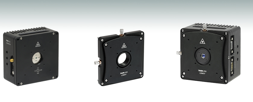
- Mounts for Ø3.8 mm, Ø5.6 mm, and Ø9.0 mm TO-Can Laser Diodes
- Flexure Adapter for Translation of Collimating Aspheric Lens
- Compatible with SM1 Lens Tubes and 30 mm and 60 mm Cage Systems
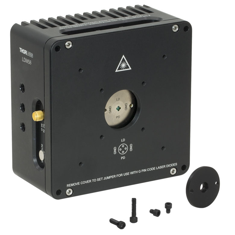
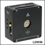
LDM56
Ø5.6 mm Laser Diode Mount
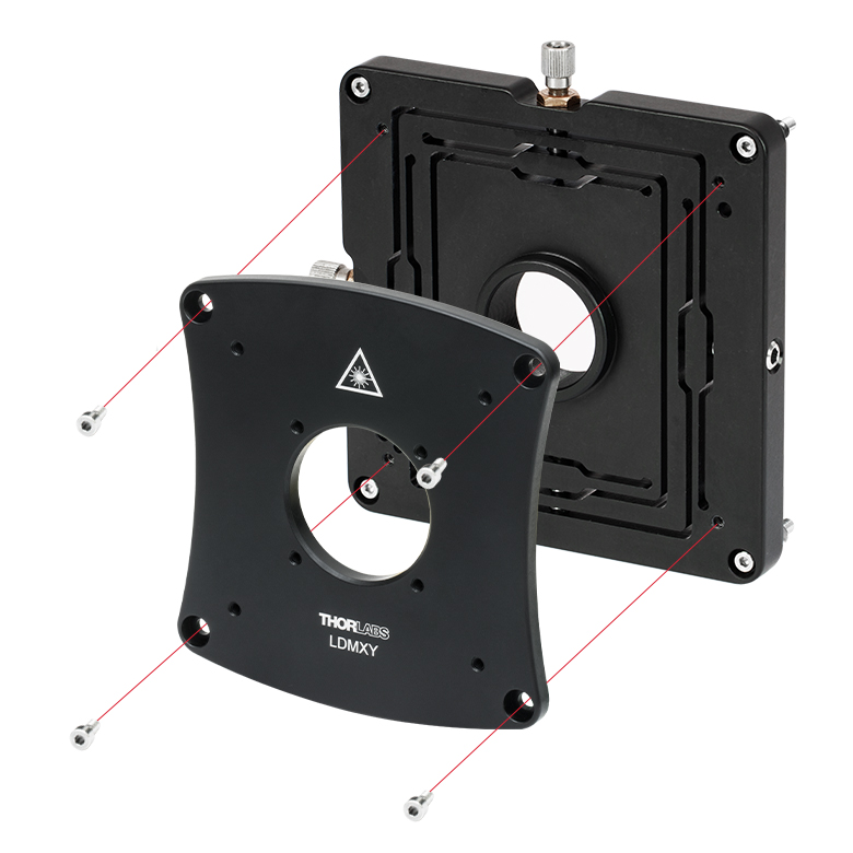
LDMXY
Flexure Adapter for
Collimating Optic
Application Idea
Mount with Laser Diode, LDMXY Flexure Adapter,
and Collimating Lens in Aspheric Lens Adapter
(Each Sold Separately)
OVERVIEW
Click to Enlarge
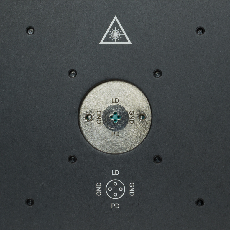
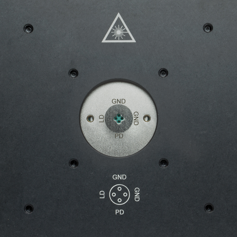
Figure 1.2 LDM56 and LDM90 Socket with SM1 Threading and Taps for
Cage Systems
(Click for Photo of LDM56F Socket)
Click to Enlarge
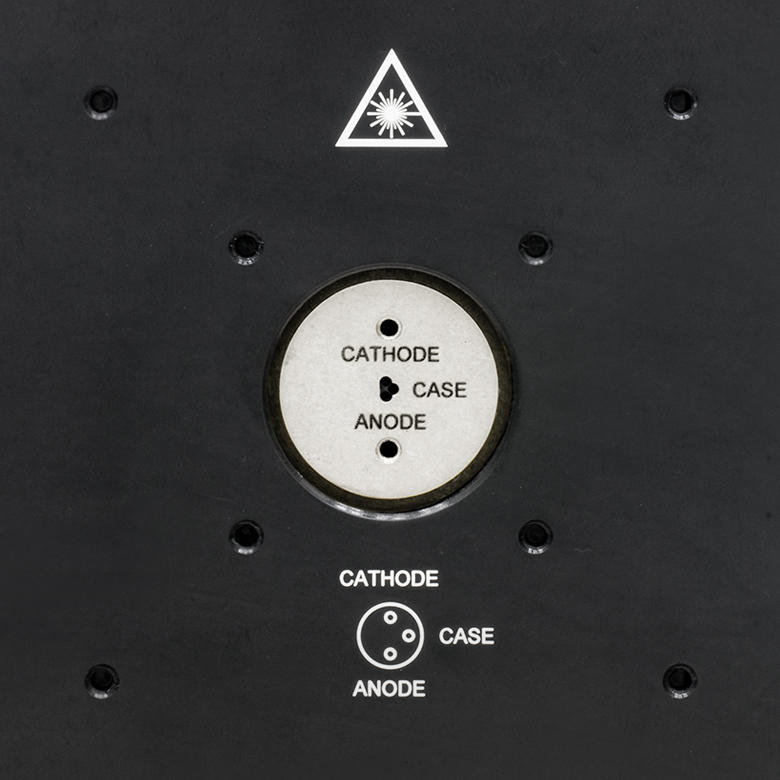
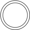
Figure 1.1 LDM38 Socket with SM1 Threading and Taps for Cage Systems
| Table 1.3 Supported Laser Diodes | ||
|---|---|---|
| Item # | TO Can Size | Pin Code |
| LDM38(/M) | Ø3.8 mm | G |
| LDM56(/M) | Ø5.6 mma | A, B, C, D, E, Gb, and H |
| LDM56F(/M) | Ø5.6 mma | F and G |
| LDM90(/M) | Ø9.0 mm | A, B, C, D, E, Gb, and H |
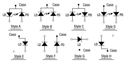
Figure 1.4 Pin Codes - See Table 1.3 for Supported Styles
Features
- Integrated TEC Element for Temperature-Controlled Operation of a Laser Diode
- Compatible with Ø3.8 mm, Ø5.6 mm, or Ø9.0 mm TO-Can Laser Diodes (See Table 1.3)
- Integrated Bias-T Network Allows for RF Modulation of LD Current up to 600 MHz
- Integrated TEC Lockout Circuit to Protect Laser Diode (Can Be Disabled)
- 8 W Heating/Cooling Capacity
- Flexure Adapter for Collimating Optic Alignment (Sold Separately)
- Compatible with 30 mm and 60 mm Cage Systems
- Compatible with SM1 Lens Tube System
- 1/4"-20 (M6) Tapped Holes for Post Mounting
Thorlabs' LDM Series Laser Diode Mounts with Integrated TEC (Thermoelectric Cooler) are ideal for temperature-controlled operation of standard laser diodes in Ø3.8 mm, Ø5.6 mm, or Ø9.0 mm TO-can packages. Laser diodes can be quickly and easily installed by inserting the laser diode into the socket according to the imprinted pin assignment and fastening the mounting flange with two screws (5/64" [2.0 mm] hex). Each mounting flange offers tweezer slots for easy insertion and removal. The diode socket is located very close to the front of the cold plate, making the connection of short lead devices easier. We also offer a TE-cooled mount for pigtailed TO-can laser diodes.
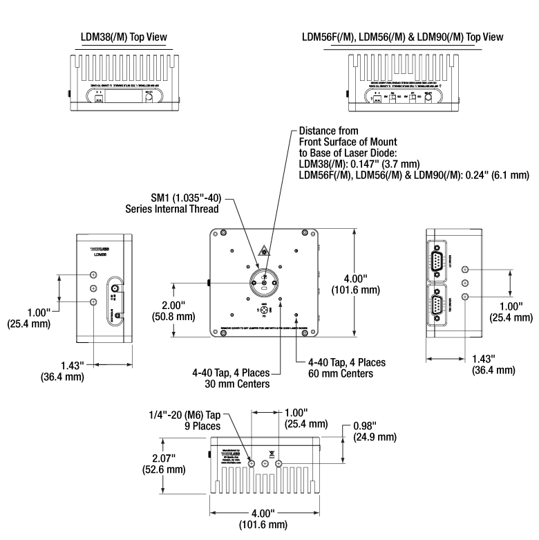
The bottom and sides of each mount provide nine 1/4"-20 (M6) mounting holes that are each 1/4" (6.4 mm) deep. Its front face is equipped with tapped holes to mount our 30 mm and 60 mm Cage Systems and SM1 threading for use with our SM1 Lens Tubes. The laser diode socket is centered within the housing and is 2.00" (50.8 mm) above the tapped post mounting holes.
Modulation and Temperature Control
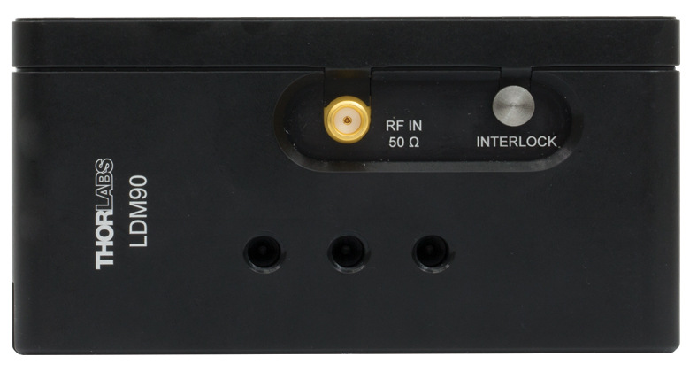
Each mount includes an internal Bias-T network for RF modulation of the laser current from 100 kHz up to 500 MHz (Item # LDM38) or 600 MHz (Item #s LDM56, LDM56F, and LDM90) using the SMA connector on the side of the mount. The maximum RF modulation power is 200 mW. User protection features include an LED on the top of the mount indicating an enabled laser and a remote interlock connector located on the side.
The built-in TE cooler enables temperature-controlled operation of the laser diode. The mounting flange protects the laser diode against air drafts, allowing temperature stabilities of about 10 mK to be achieved. Laser protection features include optional grounding configurations and a 'TEC Lockout' circuit (also included in our 14-Pin Butterfly Laser Diode Mounts) that prevents enabling the laser unless the TEC controller is active. The TEC Lockout only functions with Thorlabs' LD and TEC controllers and can be bypassed if not required.
Flexure Adapter for Collimation Optic Alignment
The LDMXY Flexure Adapter for LDM Series Mounts provides ±1.0 mm of XY translation for collimation optics. The translating optic cell is SM1 threaded for compatibility with our aspheric lens adapters and aspheric lenses. See the LD Collimation tab for more information on selecting collimation optics. The front slip plate also offers ±1.0 mm of coarse XY translation independently of the SM1-threaded optic cell and features the same eight 4-40 taps for 30 mm and 60 mm cage system compatibility. This isolates the load of attached cage systems to the laser diode mount rather than the flexure mechanism. Four standard cap screws can be loosened to adjust the slip plate, while four captive screws are used to attach the LDMXY adapter to the LDM Series Mount. All screws are compatible with 5/64" (2.0 mm) hex balldrivers and hex keys.
Recommended Current and Temperature Controllers for Laser Diode Mounts
These mounts are compatible with all of Thorlabs' LDC Series LD Controllers and ITC Series Combined LD/TEC Controllers. For temperature control when not using a combined LD/TEC controller, we recommend one of our Temperature Controllers. The appropriate cables with DB9 connectors are included with each Thorlabs controller and ensure that the controllers cannot be connected incorrectly. Additionally, these controllers have built-in protection circuitry that protects the laser when not in use. For more information, please see the Electronic Control tab.
Click to Enlarge
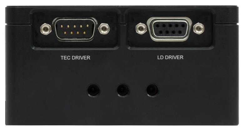
Figure 1.5 Right Side: DB9 Connectors for LD and TEC
(See Pin Diagrams Tab for Details)
Click to Enlarge
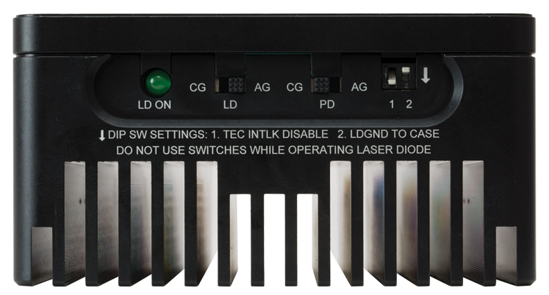
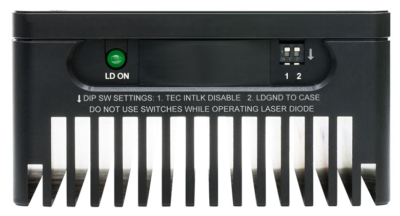
Figure 1.6 Top Side: Pin Code Configuration Switches
(LDM56F, LDM56, and LDM90; See Pin Configurations Tab for Details;
Click for Photo of LDM38 Top Side)
Click to Enlarge
Figure 1.7 Left Side: RF In and Interlock Connectors
(See Pin Diagrams Tab for Details)
SPECS
| Item # | LDM38(/M) | LDM56(/M) | LDM56F(/M) | LDM90(/M) | |
|---|---|---|---|---|---|
| Laser Diode | |||||
| Supported Laser Diode Package | Ø3.8 mm | Ø5.6 mma | Ø9.0 mm | ||
| Supported Pin Configuration(s) | G | A, B, C, D, E, Gb, and H (Switch Selectable) |
F and G (Switch Selectable) |
A, B, C, D, E, Ga, and H (Switch Selectable) |
|
| Accepted Pin Lead Diameter | 0.008" - 0.016" (0.2 - 0.41 mm) | 0.015" - 0.020" (0.38 mm - 0.51 mm) | |||
| Accepted Pin Lead Length | 0.177" - 0.250" (4.50 mm - 6.35 mm) | 0.26" - 0.40" (6.5 - 10.1 mm) | 0.30" - 0.60" (7.5 - 15.2 mm) | ||
| Pin Hole Array Diameter | 0.06" (1.4 mm) | 0.08" (2.0 mm)a | 0.10" (2.5 mm) | ||
| Laser Diode Depthc | 0.147" (3.7 mm) | 0.24" (6.1 mm) | |||
| Laser Current (Max, Tambient = 25 ºC) | 1 A | 2 A | |||
| RF Modulation Frequency (Bias-T) | 100 kHz to 500 MHz | 100 kHz to 600 MHz | |||
| RF Input Impedance | 50 Ω | ||||
| RF Max Power | - | 200 mW | |||
| Temperature Controller | |||||
| TEC Current (Max) | 5.6 A | 5 A | |||
| TEC Voltage (Max) | 3.6 V | 4 V | |||
| TEC Heating/Cooling Capacity (Tambient = 25 ºC) |
8 W | ||||
| Typical Temperature Range (LD Dependent) |
- | 0 to 70 °C | |||
| Temperature Sensors |
Thermistor | 10 kΩ ± 2.2% @ 25 °C, NTC, β = 3984 K |
10 kΩ ± 3% @ 25 °C, NTC, β = 3977 K ± 0.75% |
||
| Thermocouple | AD592AN (1 μA/°K) | ||||
| Common Specifications | |||||
|---|---|---|---|---|---|
| Laser Interface | DB9 Female | ||||
| TEC Interface | DB9 Male | ||||
| RF Modulation Connector | SMA | ||||
| Interlock Connector | 2.5 mm Phono Jack | ||||
| Indicator | Green LED - LD Enabled | ||||
| Mounting Holes |
Imperial Mounts | 1/4"-20 (9 Places) | |||
| Metric Mounts | M6 x 1.0 (9 Places) | ||||
| Cage Compatibility | 4-40 Taps (8 Places) for 30 mm and 60 mm Cage Systems |
||||
| Operating Temperature | 10 to 40 °C | ||||
| Storage Temperature | 10 to 80 °C | ||||
| Dimensions (L x W x D) | 4.00" x 4.00" x 2.07" (101.6 mm × 101.6 mm × 52.6 mm) |
||||
| Weight | 1.9 lbs (0.87 kg) | ||||
Click for Details
Figure 2.1 Mounting Features Diagram
PIN DIAGRAMS
LD Driver: D-Type Female
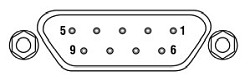
| Pin | Signal | Description (Item #s LDM38(/M), LDM56(/M), and LDM90(/M)) | Description (Item # LDM56F(/M)) |
|---|---|---|---|
| 1 | Interlock and Status Pin (LDC Specific) |
Laser Diode (LD) Status Indicator and Interlock Circuits input. | |
| 2 | Photodiode Cathode | This pin is connected to the 9 o'clock pin on the laser socket when the photodiode (PD) polarity switch is set to anode ground (AG). It is attached to ground and the 12 o'clock and 6 o'clock pins on the laser socket when the PD polarity switch is set to cathode ground (CG). | This pin is connected to the 6 o'clock pin on the laser socket when the photodiode (PD) polarity switch is set to anode ground (AG). It is attached to ground and the 12 o'clock and 3 o'clock pins on the laser socket when the PD polarity switch is set to cathode ground (CG). |
| 3 | Laser Ground (Case) | This pin is connected to the 3 o'clock and 9 o'clock pins on the laser socket and corresponds to the settings of the LD and PD polarity switches (i.e. If the LD and PD switches are set to AG then this pin grounds the anodes of the laser and photodiodes). | This pin is connected to the 12 o'clock and 3 o'clock pins on the laser socket and corresponds to the settings of the LD and PD polarity switches (i.e. If the LD and PD switches are set to AG then this pin grounds the anodes of the laser and photodiodes). |
| 4 | Photodiode Anode | This pin is connected to the 6 o'clock pin on the laser socket when the PD polarity switch is set to CG. It is attached to ground and the 3 o'clock and 9 o'clock pins on the laser socket when the PD polarity switch is set to AG. | This pin is connected to the 6 o'clock pin on the laser socket when the photodiode (PD) polarity switch is set to cathode ground (CG). It is attached to ground and the 12 o'clock and 3 o'clock pins on the laser socket when the PD polarity switch is set to anode ground (AG). |
| 5 | Interlock and Status Return |
Status and interlock circuitry return. | |
| 6 | Laser Diode Voltage (Cathode) |
This pin is connected to LD interface pin 7, through a 499 Ω resistor, when the LD polarity switch is set to AG. It is attached directly to LD interface pin 3 when the LD polarity switch is set to CG. | |
| 7 | Laser Diode Cathode | This pin is connected to the 12 o'clock pin on the laser socket when the LD polarity switch is set to AG, and it floats otherwise. | This pin is connected to the 9 o'clock pin on the laser socket when the LD polarity switch is set to AG, and it floats otherwise. |
| 8 | Laser Diode Anode | This pin is connected to the 12 o'clock pin on the laser socket when the LD polarity switch is set to CG, and it floats otherwise. | This pin is connected to the 9 o'clock pin on the laser socket when the LD polarity switch is set to CG, and it floats otherwise. |
| 9 | Laser Diode Voltage (Anode) |
This pin is connected to LD interface pin 8, through a 499 Ω resistor, when the LD polarity switch is set to CG. It is attached directly to LD interface pin 3 when the LD polarity switch is set to AG. | |
TEC Controller: D-Type Male
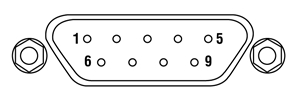
| Pin | Signal | Description |
|---|---|---|
| 1 | TEC Lockout (+) | This pin is connected to the anode of the photo-relay side of the TEC Lockout circuit. When using Thorlabs TEDs no external circuitry is required. To use these features with third-party controllers please refer to the Status and Interlock section of the mount's manual. |
| 2 | +Thermistor | The 10 kΩ at 25 °C NTC thermistor (provided for temperature feedback). |
| 3 | -Thermistor | The thermistor return pin. |
| 4 | +TEC | This pin is connected to the positive terminal of the TEC element. |
| 5 | -TEC and TEC Lockout (-) | This pin is connected to the negative terminal of the TEC element, and also is common to the cathode of the photo-relay of the TEC Lockout circuit - refer to the Status and Interlock section of the mount's manual. |
| 6 | N.C. | Not Used. |
| 7 | AD592(-) | The negative terminal of the AD592 temperature transducer. When using Thorlabs TEDs no external circuitry is required. To use this device with third party controllers it must be properly biased. Refer to Analog Devices AD592 Data for application information. |
| 8 | N.C. | Not Used. |
| 9 | AD592(+) | The positive terminal of the AD592 |
Optional Remote Interlock
2.5 mm Female Mono Phono Jack
| Specification | Value |
|---|---|
| Type of Mating Connector | 2.5 mm Mono Phono Jack |
| Open Circuit Voltage | +5 VDC with Respect to System Ground (When Used in Conjunction with Thorlabs Drivers) |
| Short Circuit Current | 10 mA DC (Typ.) |
| Connector Polarity | Tip: Positive; Barrel: Ground |
| Interlock Switch Requirements | Must be N.O. dry contacts. Under no circumstances should any external voltages be applied to the Interlock input. |
RF Laser Modulation Input
SMA Female
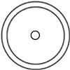
Figure 3.1 RF input for modulation with an external source. This is a 50 Ω input that is AC-coupled directly to the laser through a Bias-T network.
PIN CONFIGURATIONS
Figure 4.1 Thorlabs Pin Configurations
Laser Diode Pin Configurations
Thorlabs offers many different TO can laser diodes that emit in the UV, visible, and NIR. Many laser diode packages also include a built-in monitor photodiode, and the electrical connections for the diodes vary based on the internal circuitry of the package. Thorlabs labels these different configurations, shown in Figure 4.1, as Styles A through H. Thorlabs notes the pin configuration styles of the diodes we offer both in the specifications provided on our website and on the specification sheets included with the diodes. To determine the style of any laser diode package, compare its pin diagram supplied with the styles shown in Figure 4.1. Use the style type, pin configuration, and the following information to properly power the laser diode.
The laser diode orientation is engraved on the front of each mount and also shown in Figures 4.2 through 4.4.
LDM38 Mount Compatibility
The LDM38 Laser Diode Mount is compatible with Ø3.8 mm laser diodes with a G pin configuration as depicted in Figure 4.1. Full details of the assembly and operation of the LDM38 Mount can be found in the LDM38 operating manual.
LDM56 and LDM90 Mount Compatibility
The LDM56 and LDM90 Laser Diode Mounts are compatible with all three-pin Ø5.6 mm and Ø9 mm laser diode packages, respectively, that have an A, B, or C pin configuration style. These configurations include both a laser diode and a monitor photodiode, and the packages feature a common ground pin and independent control of the Laser Diode (LD) and Photodiode (PD) voltages.
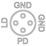
Figure 4.4 LDM56F Standard Configurations
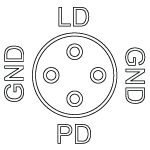
Figure 4.3 LDM56 and LDM90 Standard Configurations
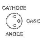
Figure 4.2 LDM38 Standard Configurations
Click to Enlarge
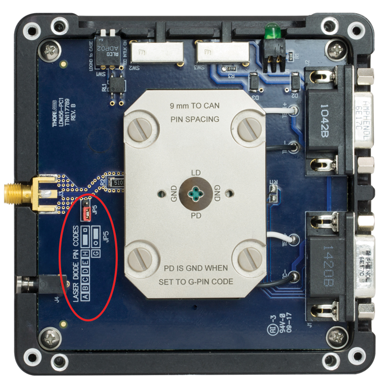
Figure 4.5 Internal Circuitry of LDM90 Mount Showing Jumper JP5
These mounts are also compatible with Style E, G, and H laser diodes, which do not possess a monitor photodiode. These are three-pin packages that include a laser diode pin and a ground pin, as shown in Figure 4.1. When used with Style G pin code laser diodes, an internal jumper must be set behind the front cover, as illustrated in Figure 4.5. See the Style G Configuration section for more details.
Lastly, the LDM56 and LDM90 mounts are also compatible with all of our currently available four-pin laser diodes possessing a Style D configuration (see Figure 4.1). As with Style A, B, and C laser diodes, Style D laser diodes feature a laser diode and monitoring photodiode; however, the photodiode floats with respect to the case in Style D packages.
Please note that while Style D and Style F packages appear similar, the LDM56 and LDM90 mounts are NOT compatible with Style F four-pin package configurations. The Style F pin configuration has a pin layout that prohibits its use in these mounts. Please use the LDM56F mount for Ø5.6 mm laser diodes with a style F pin configuration.
Full details of the assembly and operation of the LDM56 and LDM90 Mounts can be found in the LDM56/LDM90 operating manual. The LDM56 mount may also be compatible with certain TO-46 package laser diodes. Please contact Tech Support for more information.
LDM56F Mount Compatibility
The LDM56F Laser Diode Mount is compatible with Ø5.6 mm laser diodes with an F or G pin configuration as depicted in Figure 4.1. Full details of the assembly and operation of the LDM56F Mount can be found in the LDM56F operating manual. The LDM56F mount may also be compatible with certain TO-46 package laser diodes. Please contact Tech Support for more information.
Style G Configuration for LDM56 and LDM90 Mounts
Style G configurations feature only a laser diode in the package; no photodiode is present. This style of laser diode is directly compatible with our LDM56F mount. It is also compatible with our LDM56 or LDM90 mounts, but a minor change must be made inside since the LD and ground pins are directly across from each other (i.e. in the LD and PD positions or 3 and 9 o'clock positions).
In order to drive a style G laser diode in our LDM56 or LDM90 mounts, the PD pin in the mount must be grounded. To ground the PD pin, remove the front cover of the mount. Locate jumper JP5 on the left-hand side of the mount. A photo of the internal circuitry is shown in Figure 4.5, and jumper JP5 is circled. Grounding the photodiode pin will allow the mount to drive a laser diode only (no photodiode) configuration with the LD pin at the 12 o'clock position. Follow the engraved guide for configuring the jumper based on the laser diode pin code.
ELECTRONIC CONTROL
Laser Diode Current Controllers
The laser diode current controller should be chosen to be compatible with the particular laser diode and application. Thorlabs offers a wide variety of laser diode controllers ranging from low power (low current and low voltage) to high power (high current and/or voltage) versions. Thorlabs also offers several dual laser diode current/temperature controllers. See the TEC Controllers section that follows for discussion of the temperature controllers.
Thorlabs' LDC2xxC series of controllers are suitable for use with a large majority of popular laser diodes. Thorlabs' LDC200CV is specifically designed to handle and safely operate Vertical Cavity Surface Emitting Lasers (VCSELs), while the LDC201CU provides users with an ultra-low noise current (<0.2 μA RMS) for stable operation of low power laser diodes. If your application requires the higher voltages typically necessary for driving blue and other short laser diodes, consider our LDC202C, LDC205C, or LDC210C controller. For driving higher power laser diodes, the LDC220C and LDC240C offer drive currents of 2 A and 4 A, respectively. Higher current (5 and 20 A), T-Cube-compatible, and rack mount controllers are also available. All of these controllers operate in a similar manor. Only the LDC2xxC series controllers will be discussed in more detail.
TEC Controllers
Thorlabs also offers a wide variety of TEC controllers as stand-alone units and dual laser diode/ temperature controllers. The TED200C benchtop temperature controller is ideally suited to regulate the temperature of a laser diode mounted in our LDM Series Laser Diode Mounts. This unit features a wide operating temperature range, 12 W of cooling, and high temperature stability. For more cooling power and even higher temperature stability, the TED4015 225 W temperature controller can be used.
The TEC elements in these mounts can be connected to a temperature controller via the DB9 female connection on the side of the unit. Adapter cables are available for temperature controllers with other connector types. For third-party controllers, please refer to the operating manual for pin layouts and descriptions. Follow the instructions for the TEC controller, paying careful attention not to overdrive the TEC elements in the mount.
RF Modulation
Modulation of a laser diode is possible but not via the laser diode controller. The input from the laser diode controller is sent through an inductor that only allows low bandwidth, DC currents to pass through to the laser diode. To allow high frequency modulation of the laser diode, the mount's built-in bypass needs to be used to circumvent the low pass filter. The bypass is accessed through an SMA connector on the side of the mount, is directly coupled to the laser using a bias-T network, and features a 50 Ω RF input that can accept an AC-coupled RF source up to 500 MHz (Item # LDM38) or 600 MHz (Item #s LDM56, LDM56F, and LDM90).
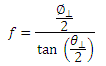
In order to properly modulate the laser diode emission, the correct modulation voltage must first be determined. The modulation voltage, VRF, is determined from the product of the laser diode modulation current, ILD, and the input impedance, Zinput:
ILD is given by the manufacturer, and Zinput is the impedance of the mount, which is equal to 50 Ω.
When setting the modulation voltage, it is recommended to start at a factor of 10 lower than the value determined from Eq. 1. The modulation voltage can then be slowly increased until VRF or the desired modulation is achieved. The laser diode controller can then be used to increase DC voltage to the proper level.
Warning: The RF input is directly coupled to the laser diode. There is no suppression of noise or other spurious signals to the laser diode. Stable and clean RF sources should be used to avoid overdriving the laser diode. In addition, the laser diode can be easily overdriven by an RF voltage above the specified level in Eq. 1. Take care when controlling and adjusting the RF voltage to avoid damage to the laser diode.
Safety Interlock
These mounts are equipped with a Remote Interlock connector located on the side panel. In order to enable the laser source, a short circuit must be applied across the terminals of the remote interlock connector. In practice this connection is made available to allow the user to connect a remote actuated switch to the connector (i.e. an open door indicator). The switch (which must be normally open) has to be closed in order for the unit to be enabled. Once the switch is in an open state the laser diode must automatically shut down.
All units are shipped configured with a shorting device installed in the interlock connector. If you are not going to use this feature then you can leave the shorting device installed and the unit will operate normally. If you wish to make use of the interlock feature you will need to acquire the appropriate connector mate and wire it to your remote interlock switch. Next, remove the shorting device by pulling it from the input and install the connector into the interlock input.
The interlock input only accepts a 2.5 mm mono phono jack. This connector is readily available at most electronics suppliers.
LD SETUP
Video Insight: Setting Up a TO Can Laser Diode
Installing a TO can laser diode in a mount and setting it up to run under temperature and current control presents many opportunities to make a mistake that could damage or destroy the laser. This step-by-step guide includes tips for keeping humans and laser diodes safe from harm.
If you would like more information about tips, tricks, and other methods we often use in the lab, we recommend our other Video Insights. In addition, our webinars provide practical and theoretical introductions to our different products.
LD COLLIMATION
Choosing Collimation and Ellipticity Correction Optics for Your Laser Diode
Since the output of a laser diode is highly divergent, collimating optics are often necessary. Due to their excellent ability to correct spherical aberration, aspheric lenses are the most commonly used optics when the desired collimated beam waist is between one and five millimeters. Choosing an appropriate aspheric lens for collimating a laser diode is essential, as the resulting beam size and transmission range are dependent on the lens used. To calculate the beam size of a collimated laser diode, we first need to know its divergences.
The beam divergences of an edge-emitting laser diode will be different in the parallel and perpendicular directions, leading to an elliptical beam. This can be compensated for by inserting anamorphic prism pairs or cylindrical lenses into the collimated beam. The divergences are typically specified as "Beam Divergence (FWHM) - Parallel" and "Beam Divergence (FWHM) - Perpendicular" for the two axes of the chip. There are variations from lot to lot of laser diodes, but using the typical divergence values should be adequate for most applications.
The simple example below will illustrate the key specifications to consider when choosing the correct optics for a given application.
Example: 785 nm, 25 mW Laser Diode, L785P25, Ø3 mm Desired Collimated
Step 1: Collimating Emission
The specifications for the L785P25 laser diode indicate that the typical perpendicular and parallel beam divergences are 30o and 8o, respectively. The major (perpendicular) beam divergence is shown in Figure 66A. The minor (parallel) beam divergence is shown in Figure 66B. Because of this asymmetry in the two axes, an elliptical beam will form as the light diverges. To collect as much light as possible during the collimation process, consider the larger of these two divergence angles in any calculations (i.e., in this case use 30o).
Note: Parallel and perpendicular notation are specified relative to the junction plane of the laser diode.
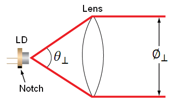
Figure 66A Perpendicular beam divergence from L785P25 style B laser diode
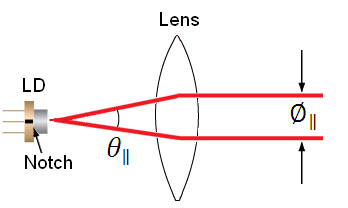
Figure 66B Parallel beam divergence from L785P25 style B laser diode
In Figures 66A and 66B, LD denotes the laser diode,  and
and  are the beam diameters in the parallel and perpendicular orientations, respectively, and
  and
and  are the divergence angles in the parallel and perpendicular orientations, respectively. Please note that the notch in Figures 66A and 66B can be used to determine the orientation of the laser diode within the package. Laser diodes are typically oriented parallel to the notch; however there are many exceptions, especially for different laser diode packages. Care should be taken to note the orientation of the laser diode emission.
To calculate the focal length needed to achieve a Ø3 mm collimated beam diameter, we can use:
where  is the focal length that produces the desired perpendicular beam diameter, . The focal length of the lens needed to collimate a 30o diverging beam into a Ø3 mm collimated beam is = 5.6 mm.
This equation yields the focal length to achieve our desired major (perpendicular) axis diameter. Use this to then select an aspheric lens with a focal length that most closely matches the focal length given by the equation. Please note that the diameter of the lens must be larger than your desired major axis beam diameter.
Thorlabs offers a large selection of aspheric lenses. For this application, the ideal lens is an -B AR-coated molded glass aspheric lens with focal length near 5.6 mm. The C171TMD-B (mounted) or 354171-B (unmounted) aspheric lenses have a focal length of 6.20 mm. Next, check to see if the numerical aperture (NA) of the diode is smaller than the NA of the lenses so that the light emitted from the laser diode is not clipped by the lens:
0.30 = NALens > NADiode ~ sin(15) = 0.26
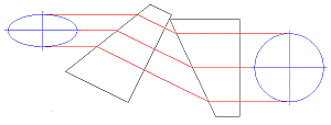
Figure 66C Anamorphic Prism Pair and optic trace for an ellipse to round beam.
Solving the first equation again with your actual focal length and major axis divergence angle yields the actual major axis beam diameter, = 3.3 mm.
Step 2: Correcting Ellipticity
Emission from an edge emitting laser diode is elliptical (asymmetric with respect to two different axes), as shown in Figures 66A and 66B. To correct for this and produce a circular beam, the minor axis diameter, , can be magnified using anamorphic prism pairs or cylindrical lenses after collimation. Note: only cylindrical lens pairs can correct for any astigmatism present in the diode output. Figure 66C shows an anamorphic prism pair magnifying an elliptical beam minor axis to produce the desired symmetric beam.
To determine what magnification of the minor axis is needed to produce a round beam, solve Eq. 1 using the focal length from the aspheric lens,![]() = 6.20 mm, = 8o, instead of the major axis divergence. This results in a minor axis diameter, = 0.9 mm. Comparing and , we see that a 3.5X magnification is necessary in the minor beam axis. This 3.5X magnification can be achieived using the PS881-B Mounted Anamorphic Prism Pair.
= 6.20 mm, = 8o, instead of the major axis divergence. This results in a minor axis diameter, = 0.9 mm. Comparing and , we see that a 3.5X magnification is necessary in the minor beam axis. This 3.5X magnification can be achieived using the PS881-B Mounted Anamorphic Prism Pair.
Lens Tube Mounting
For mounted aspheric lenses, our SM05Txx or S1TMxx adapters can be used. Take care to ensure that the lens does not contact the laser diode. The SM05Txx adapters will require the use of an SM1A6T SM1-to-SM05 adapter.
Unmounted aspheres can be epoxied to an LMRAxx adapter, which can then be mounted in an SM1A6T SM1-to-SM05 adapter. The SM1 threading of the adapter can then be used to attach the lens/mount/adapter to the laser diode mount's front plate. The SM1A6T adapter has a mounting range of 10 mm, covering almost the entire focal length range of our aspheric lenses.
In the above example, the C171TMD-B mounted lens features M8 x 0.5 threading, thus requiring the S05TM08-threaded adapter. The S05TM08 M8-to-SM05 adapter can be mounted in the laser diode mount using the SM1A6T SM- to-SM05 adapter. The correct distance between the laser diode and lens can be achieved by adjusting both the S05TM08 and the SM1A6T adapters.
If the 354171-B, unmounted ashperic lens is used, it must first be epoxied to the LMRA5 adapter. It can then be mounted in the SM1A6T SM1-to-SM05 adapter. Again, adjustment of the aspheric lens can be made at the LMRA5 and SM1A6T adapters.
Cage Assembly Mounting
Mounted and unmounted aspheric lenses with focal lengths greater than 8 mm can be cage mounted using our 30 mm cage system. Cage rods can be attached directly to the front plate of the laser diode mount. The CP33(/M) cage plate may be used to hold the S1TMxx adapter with mounted aspheric lens or the SM1A6T adapter with unmounted aspheric lens epoxied to an LMRAxx adapter.
For larger translational adjustments, the CT1A(/M) 1/2" Travel Translator can be used. The CT1A(/M) translator has a graduated micrometer which provides 1/2" (13 mm) of linear translation and has 0.001" (10 µm) graduations. The smallest incremental movement of the carriage is approximately 1 µm.
Anamorphic Prism Pair Mounting
The asymmetric output of the laser diode can be corrected using either anamorphic prisms or cylindrical lenses. As determined in the example above, a 3.5X mounted anamorphic prism pair (i.e., PS881-B) was needed to produce a round beam profile. Unmounted prisms may be used as well.
The PS881-B Mounted Anamorphic Prism Pair features SM05 threading on the output end or may be mounted inside an SM1 Lens tube. Since the input and output beams from the Anamorphic Prism Pair are offset from each other, prisms should be mounted on another cage or lens tube axis.
LD MOUNT SELECTION GUIDE&NBSP;
| Laser Diode Mount Selection Guide | |||||||
|---|---|---|---|---|---|---|---|
| Item # | LDM38(/M) | LDM56(/M) | LDM56F(/M) | LDM90(/M) | LDM21 | LDM9T(/M) | |
| Click Photo to Enlarge | 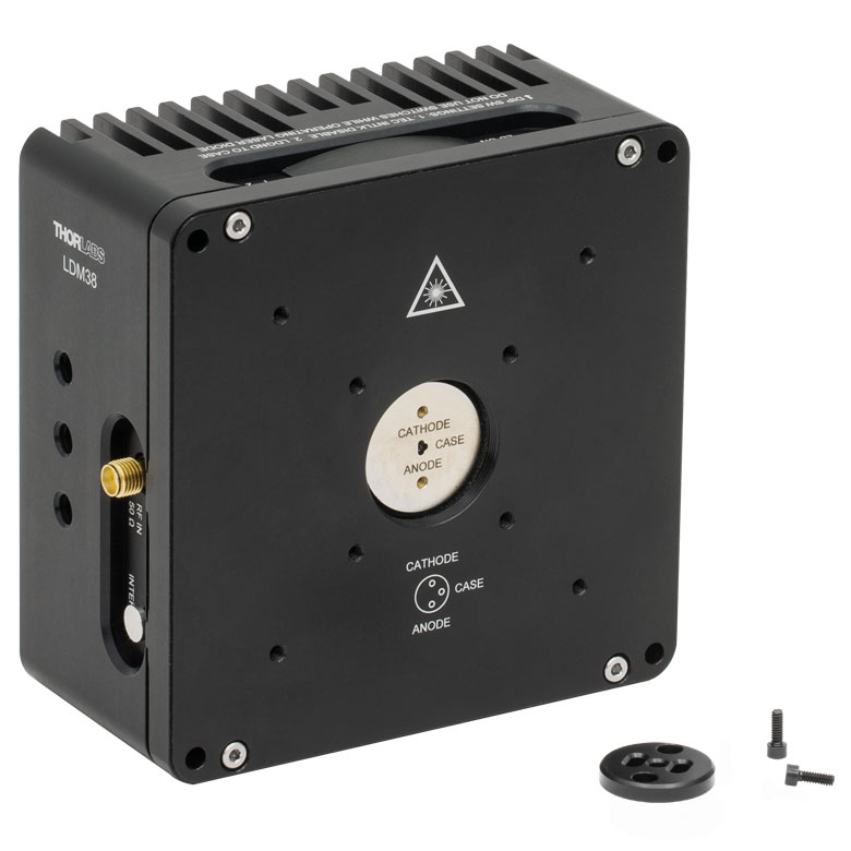 |
 |
 |
 |
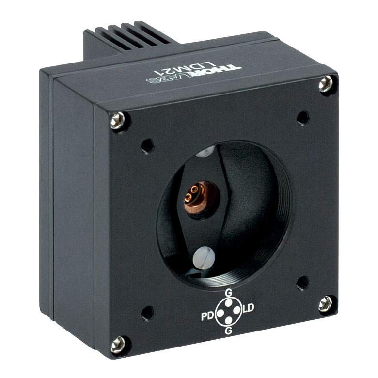 |
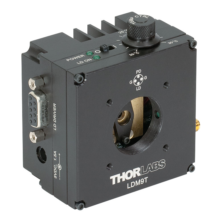 |
|
| Laser Diode | |||||||
| Supported Laser Diode Package(s) | Ø3.8 mm | Ø5.6 mm | Ø5.6 mm | Ø9 mm | Ø5.6 mm and Ø9 mm | Ø5.6 mm and Ø9 mm | |
| Supported Pin Configuration(s) | G | A, B, C, D, E, Ga, H (Switch Selectable) |
F and G (Switch Selectable) |
A, B, C, D, E, Ga, H (Switch Selectable) |
A, B, C, D, E, and H | A, B, C, D, E, G, and H (Some Modification Necessary for G Style)b |
|
| Maximum Laser Current (Tambient = 25 °C) |
1 A | 2 A | 500 mA | 200 mA | |||
| RF Modulation Frequency Rangec | 100 kHz to 500 MHz | 100 kHz to 600 MHz | N/A | 200 kHz to 1 GHz | |||
| Temperature Controller | |||||||
| TEC Heating/Cooling Capacity (Tambient = 25 °C) |
8 W | 8 W | 2 W | 0.5 W | |||
| Temperature Adjustment Range | - | 0 to 70 °C | 20 to 30 °C | ||||
| General Specifications | |||||||
| Laser Interface | DB9 Female | ||||||
| TEC Interface | DB9 Male | N/Ad | |||||
| Compatible Current and Temperature Controllers | LDC Series and T-Cube LD Controllerse, ITC Series Combined LD/TEC Controllersf, and Temperature Controllersf | LDC Series and T-Cube LD Series Controllerse |
|||||
| Mounting Features | Imperial Mounts | 1/4"-20 Tapped Hole (9 Places) | 8-32 Tapped Holeg (4 Places) |
8-32 Tapped Hole (3 Places) |
|||
| Metric Mounts | M6 x 1.0 Tapped Hole (9 Places) | N/A | M4 x 0.7 Tapped Hole (3 Places) |
||||
| Accommodations for Collimating Optics | SM1 (1.035"-40) Series Internal Thread; LDMXY Flexure Adapter (Sold Separately) |
SM1 (1.035"-40) Series Internal Thread | |||||
| Cage System Compatibility | 4-40 Tap (8 Places) for 30 mm and 60 mm Cage Systems |
4-40 Tap (4 Places) for 30 mm Cage System | |||||
| Dimensions | 4.00" x 4.00" x 2.07" (101.6 x 101.6 x 52.6 mm) |
1.75" x 1.75" x 1.66" (44.5 x 44.5 x 42.1 mm) |
3.09" x 2.89" x 1.79" (78.5 x 73.3 x 45.5 mm) |
||||
Temperature-Controlled Mount for Ø3.8 mm Laser Diodes
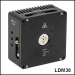
- Compatible with Ø3.8 mm TO Can Laser Diodes
- Standard Diode Package Flange Included
- Pin Code Compatibility: G Pin Code
- See Specs Tab for Complete Specifications
Part Number | Description | Price | Availability |
|---|---|---|---|
LDM38/M | TE-Cooled Mount for Ø3.8 mm Laser Diodes with G Pin Code, M6 Taps | $765.19 | Today |
LDM38 | TE-Cooled Mount for Ø3.8 mm Laser Diodes with G Pin Code, 1/4"-20 Taps | $765.19 | Today |
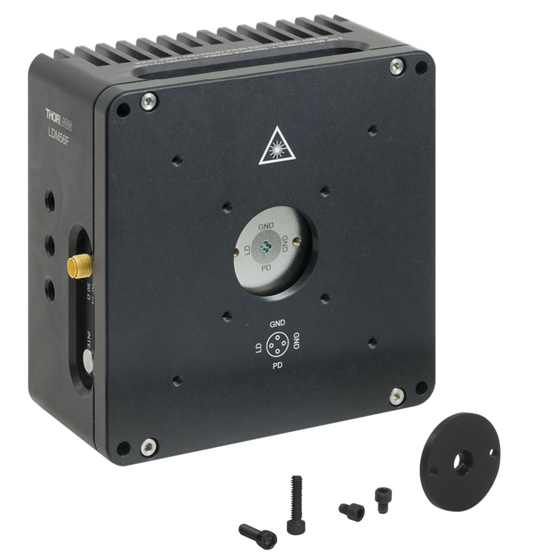
Temperature-Controlled Mounts for Ø5.6 mm Laser Diodes

Click to Enlarge
Figure G2.1 LDM56F Mount
- Compatible with Ø5.6 mm TO Can Laser Diodes
- Standard Diode Package Flange Included
- Pin Code Compatibility:
- LDM56(/M): A, B, C, D, E, G, and H Pin Codes
- LDM56F(/M): F and G Pin Codes
- See Specs Tab for Complete Specifications
- Mounting Flange for 532 nm DPSS Lasers (Compatible with LDM56 Mount) Sold Below
Part Number | Description | Price | Availability |
|---|---|---|---|
LDM56/M | TE-Cooled Mount for Ø5.6 mm Laser Diodes with A/B/C/D/E/G/H Pin Codes, M6 Taps | $810.00 | Today |
LDM56F/M | Customer Inspired! TE-Cooled Mount for Ø5.6 mm Laser Diodes with F or G Pin Codes, M6 Taps | $810.00 | Today |
LDM56 | TE-Cooled Mount for Ø5.6 mm Laser Diodes with A/B/C/D/E/G/H Pin Codes, 1/4"-20 Taps | $810.00 | Today |
LDM56F | Customer Inspired! TE-Cooled Mount for Ø5.6 mm Laser Diodes with F or G Pin Codes, 1/4"-20 Taps | $810.00 | Today |
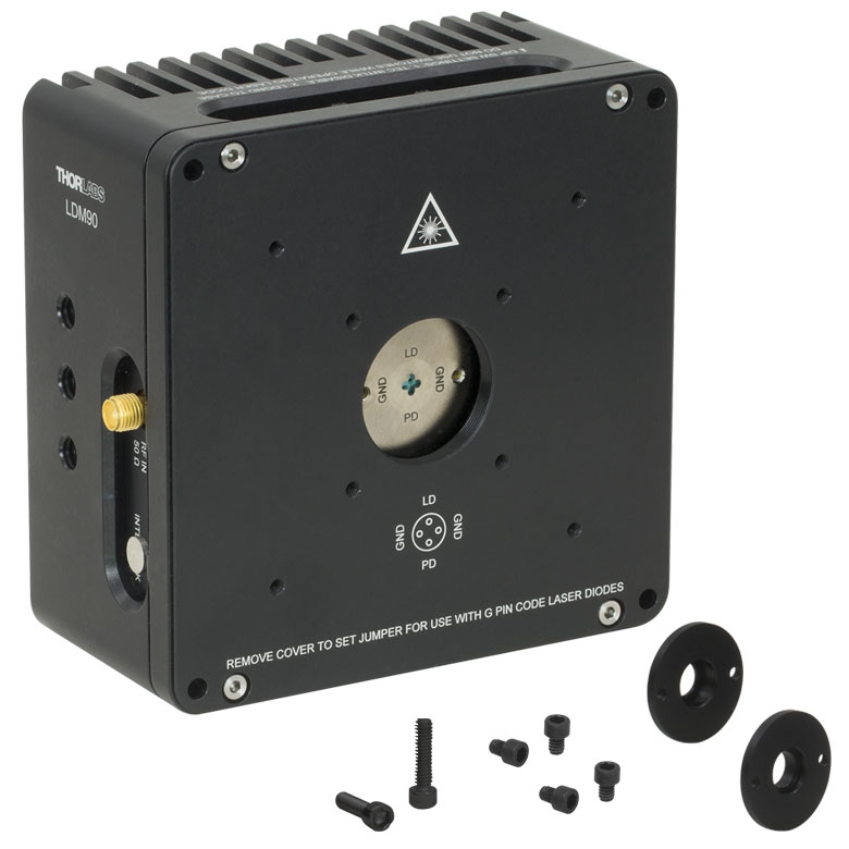
Temperature-Controlled Mount for Ø9.0 mm Laser Diodes
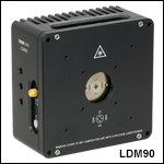
- Compatible with Ø9.0 mm TO Can Laser Diodes
- Flanges Included for Standard and High Heat Load (HHL) Diode Packages
- Pin Code Compatibility: A, B, C, D, E, G, and H Pin Codes
- See Specs Tab for Complete Specifications
Part Number | Description | Price | Availability |
|---|---|---|---|
LDM90/M | TE-Cooled Mount for Ø9.0 mm Laser Diodes with A/B/C/D/E/G/H Pin Codes, M6 Taps | $810.00 | Today |
LDM90 | TE-Cooled Mount for Ø9.0 mm Laser Diodes with A/B/C/D/E/G/H Pin Codes, 1/4"-20 Taps | $810.00 | Today |
XY Flexure Adapter
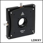
| LDMXY Adapter Specifications | |
|---|---|
| Flexure | |
| Optic Cell Travel | ±1.0 mm |
| Optic Cell Threading | SM1 (1.035"-40) Through Tapped |
| XY Adjusters | M3 x 0.25 (250 μm/rev) |
| Slip Plate | |
| Slip Plate Travel | ±1.0 mm (Coarse Adjustment) |
| Cage Compatibility | 4-40 Taps (8 Places) for 30 mm and 60 mm Cage Systems |
| General | |
| Material | Aluminum |
| Dimensions | 4.00" x 4.00" x 0.60" (101.6 mm x 101.6 mm x 15.2 mm) |
| Mass | 0.33 kg (0.73 lbs) |
- XY Flexure Translation of SM1 Thread (±1.0 mm Travel)
- Slip Plate with Cage System Taps for Independent Translation (±1.0 mm Travel)
- Compatible with 30 mm and 60 mm Cage Systems
- Mounts Directly to the Front of LDM Series Laser Diode Mounts
The LDMXY Flexure Adapter provides collimation optics with ±1.0 mm of XY translation. The translating optic cell is SM1 threaded for compatibility with our aspheric lens adapters and aspheric lenses. The front slip plate also offers ±1.0 mm of coarse XY translation independently of the SM1-threaded optic cell and features the same eight 4-40 taps for 30 mm and 60 mm cage system compatibility. This isolates the load of attached cage systems to the LDM Series LD Mount rather than the flexure mechanism. Four standard cap screws can be loosened to adjust the slip plate, while four captive screws are used to attach the LDMXY adapter to the laser diode mount. All screws are compatible with 5/64" (2.0 mm) hex balldrivers and hex keys.

Click to Enlarge
Figure 612A The LDMXY can be used to increase the working distance to the lens, as well as provide X and Y translation.
Click to Enlarge
Figure 612B The flexure translates the
SM1-threaded optic cell independently from the cage system slip plate.
Part Number | Description | Price | Availability |
|---|---|---|---|
LDMXY | XY Flexure Adapter for LDM Series Laser Diode Mounts | $441.46 | Today |
Mounting Flange for DPSS Lasers
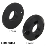
The LDM56DJ mounting flange is used to secure a 532 nm DPSS laser to the LDM56(/M) temperature-controlled laser diode mount. To use, mount either the DJ532-10 or the DJ532-40 laser in the LDM56(/M) mount. Using the two 2-56 x 3/8" cap head screws provided with the flange, or with the mount itself, attach the flange to the mount.
Please note: this flange is sold separately from the LDM56(/M) Temperature Controlled Laser Diode Mount.
Part Number | Description | Price | Availability |
|---|---|---|---|
LDM56DJ | DPSS Laser Mounting Flange for LDM56(/M) Laser Diode Mount | $32.09 | Today |