 Products Home
VideoMic® Multisensor Video Measurement Systems
- High-Speed, Non-Contact 3-Axis Coordinate Measurement
- Superior Stability and Accuracy from Granite Base and Gantry
- Multisensor: Video, Touch, and Laser Sensors
- High-Accuracy Air or Mechanical Bearings
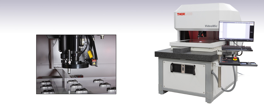
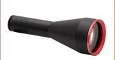
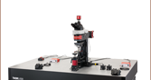
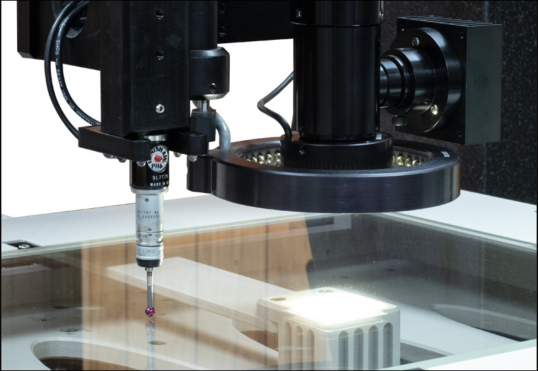
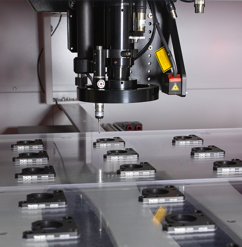
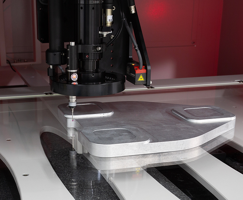
Tactile Probe Used to Measure Thorlabs' Components
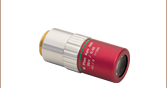
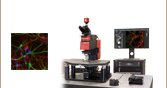
VSA713
Video Measurement System
711 mm x 610 mm x 200 mm
Range Shown with Adjustable Quadrant Light


Please Wait
Exploring the Options?
Thorlabs' Multisensor Video Systems are customized to meet the demanding needs of your application. If you do not see a product or specification that you require or you are looking for assistance selecting a system, please use the Contact Me button. Our Measurement Systems Team is happy to help and can provide system recommendations based on your needs.
In the Budgetary Phase?
System prices vary based on the exact components. Through our conversations, we can ensure your system quote is tailored to your requirements.
OEM or Custom Projects?
Click here to learn about our OEM capabilities.

Ike Jariel
General Manager
Thorlabs Measurement Systems
I'm Happy to Assist!
Want a System Demo?
Contact us to demo a system in our showroom or remotely.
Features
- XYZ Measuring Range Options:
- 460 mm x 305 mm x 200 mm (Air or Mechanical Bearings)
- 711 mm x 610 mm x 200 mm (Air or Mechanical Bearings)
- 965 mm x 760 mm x 200 mm (Air Bearings)
- 1270 mm x 915 mm x 200 mm (Air Bearings)
- All Systems Offer CNC or User-Driven Operation
- High-Resolution Video Sensors for High-Contrast Imaging
- Laser, Tactile, and Confocal Chromatic Probes for Multisensor Metrology
- Multiple LED Options to Highlight Surface and Edge Features
- Stable Granite Base Ensures High Accuracy and Repeatability
- Floor-Standing, Ergonomic Workstation for Simple and Convenient Operation
- Advanced, Feature-Rich M3 MetLogix®a Metrology Control Software
- Installation Included
Build Your Coordinate Measuring Machine
- Select a Base System (Required, See Table 1.1 for the Key Specifications and the Base Systems tab for Details)
- Select Video System Options (Required, See Video Configurations tab for Details)
- Lighting, Camera, Zoom or Bi-Telecentric Lens, Objective, and Software
- Select Additional Sensors and Accessories (Optional, See Accessories tab for Details)
- Touch Probes, Laser Sensor, Confocal Probe, Glass Platen, Software, and Hardware Upgrades
| Table 1.1 Base Systems Key Specificationsa | |||||||
|---|---|---|---|---|---|---|---|
| Base System Item # | VSA463 | VSM463 | VSA713 | VSM713 | VSA963 | VSA1273 | |
| Stage Bearings | Air | Mechanical | Air | Mechanical | Air | ||
| Stage Motors | Linear | Servo | Linear | Servo | Linear | ||
| XY Measuring Range | 460 mm x 305 mm (18" x 12") |
711 mm x 610 mm (28" x 24") |
965 mm x 760 mm (38" x 30") |
1270 mm x 915 mm (50" x 36") |
|||
| Z Measuring Range | 200 mm (8") | ||||||
| Typical Unit Dimensions | |||||||
| Accuracyb | X-Y (E2) |
(1.5 + 5L/1000) µm | (2.5 + 5L/1000) µm | (1.5 + 5L/1000) µm | (2.5 + 5L/1000) µm | (1.5 + 5L/1000) µm | |
| Z (E1) |
(1.5 + 5L/1000) µm | ||||||
| Velocity | X-Y | ≤760 mm/s | |||||
| Z | ≤150 mm/s | ||||||
| Repeatability | Z | ±3 µm at High Magnification | |||||
| Price Starting Atc | $77,230.46 | $71,391.47 | $100,586.42 | $83,069.45 | $123,942.38 | $170,436.02 | |
Measurement Applications
Electronics
- Printed Circuit Boards (PCB) and PCB Assembly (PCBA)
- Flexible Printed Circuits (FPC)
- Batteries
- Solar Panels
Plastics, Glasses, and Polymers
- Molded Components
- Films
Mechanical Components
- Machined Parts
- Stamped Parts
- Hardware (Screws, Fasteners, Inserts, and Gears)
- Medical Devices
Custom Applications
- Send a Sample Part to us for Test Measurements
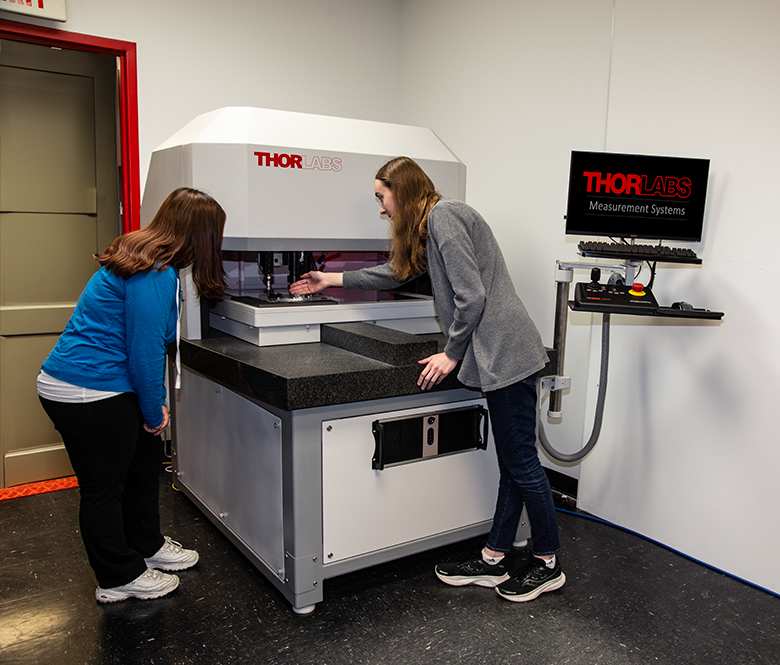
Thorlabs' VideoMic® Multisensor Video Measurement Systems provide high-speed, non-contact 3-axis coordinate measurement with industry-leading accuracy. These multisensor measuring machines can easily verify critical dimensions on first articles, production samples, or entire runs. Automated inspection protocols utilize the system's large field of view and high-resolution sensors to easily inspect large volumes of parts sequentially or simultaneously. With tolerance reports and export utilities, thresholds can be set to enable timely corrections to a production process or, when necessary, interruption of production to minimize scrap. With over 1000 systems installed worldwide, each system has a long lifetime, is completely modular, and can easily scale with the demands of any quality assurance or production facility. Product installation is included with purchase.
Six base systems are available, each utilizing a granite, split-axis base and gantry; see the Base Systems tab for details. Item numbers beginning with VSA utilize balanced linear motors with air bearings to position each axis of travel, while item numbers beginning with VSM utilize servo-driven ground-ball-screws to position each axis of travel. Each of the three motor axes and associated encoders is bonded directly onto the granite to create a system that is extremely accurate, stable, and resistant to environmental factors.
Once a base system is selected, Thorlabs offers a wide selection of CMOS cameras, zoom lenses or bi-telecentric lenses, objectives, and lights to customize the video system to the demands of the application. For further details, see the Video Configurations tab. A number of optional accessories are also available to increase the versatility and functionality of the system. These include Renishaw®b tactile probes; laser sensors; a hinged, pneumatic glass platen; statistical process control software; and import/export utilities. See the Accessories tab for additional details about these options.
Please contact TMS-Sales@thorlabs.com for help selecting or customizing a base system or to inquire about other options. We offer live demonstrations of our VideoMic systems for acquiring test images of your samples at our Sparta, NJ facility, either in person or online; please see the Live Demonstrations tab for more information.
- Metlogix is a registered trademark of Metlogix, Inc.
- Renishaw is a registered trademark of Renishaw plc.

Exploring the Options?
Our base systems can be customized to meet the needs of your application. If you would like a custom system, e.g. longer travel range, or would like to discuss our options, please contact me. Our team can provide system recommendations based on your needs.
Ike Jariel
General Manager
Measurement Systems
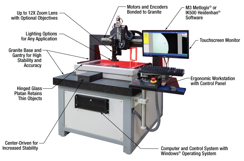
Click to Enlarge
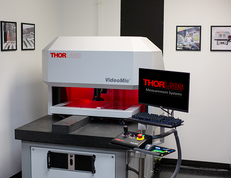
Figure 2.2 A VSA713 VideoMic System with the Hood Removed
(Shown with a Subset of Video System Options and Accessories: 12X Zoom Lens System and 0.67X Extension Tube, 1.3 MP Camera, Motorized Quadrant Light, Ring Light, Profile Light, M3 Software, and a Hinged Glass Platen)
Base System Features
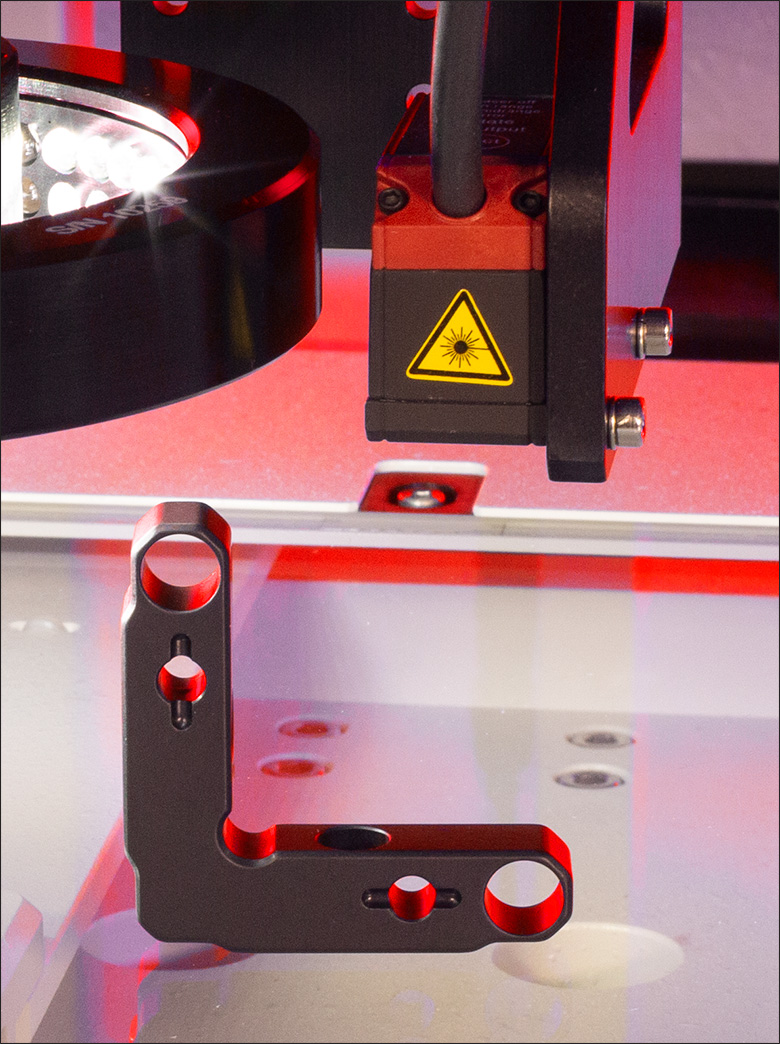
All base VideoMic® Multisensor Video Measurement Systems are video Coordinate-Measuring Machines (CMMs) that utilize a split-axis gantry design wherein the Y-axis (stage) extends below a granite bridge that supports both the X- and Z-axes (imaging system and lights) of travel. Granite, a material commonly used in quality control and metrology departments, provides a number of advantages for long-travel stages, such as those utilized in our video CMM systems. Granite resists changes in environmental temperature due to its low coefficient of thermal expansion; exhibits minimal warping over time, particularly over longer distances; and can be made extremely flat to create a near-ideal 2D plane, leading to a flatness specification of ≤5 µm over any 700 mm x 700 mm square area.
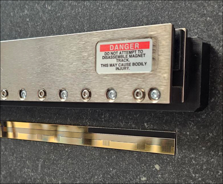
Click to Enlarge
Figure 2.1 VSA Series' Non-Contact Magnetic Track Shown Above the Gold 0.10 µm Encoder
Small and large format systems are offered to support any application. The smallest format, offering an XY measuring range of 460 mm x 305 mm (18" x 12"), is ideal for facilities with lower volumes or smaller parts to be inspected. Our largest format, offering an XY measuring range of 1270 mm x 915 mm (50" x 36"), is designed for high-volume, high-throughput facilities with large or small parts to inspect. Please see the Specs tab for the full specifications of our base systems.
Granite-Bonded Translator and Encoder
Each motor axis and associated encoder are bonded directly onto the granite, with the X- and Z-axes engineered onto the gantry and the Y-axis built onto the base. This geometry reduces the amount of machined components throughout the closed-loop control system, which increases the stiffness of the system and reduces the working distance of the Y-axis stage off the base and the camera system off the gantry. Decreasing the working distance results in a compact design that reduces the Abbe error for enhanced positioning performance.
Each axis is center-driven to reduce the influence of off-axis forces. This reduces wear and tear and improves the overall functionality of motors in each axis. When air bearings are used, a granite center guide can be seen under the Y-axis stage that the air bearings float on, as shown in Figure 2.1. This guide must be offset to the side to properly center-drive the stage when using this bearing type.
Motor and Bearing Options
Base item numbers beginning with VSA utilize balanced, non-contact, magnetic linear motors with air bearings to position each axis of travel (see Figure 2.4), while item numbers beginning with VSM utilize brushless, servo-driven ground-ball-screws to position each axis of travel. Both options will position the stages accurately, quietly, and quickly.
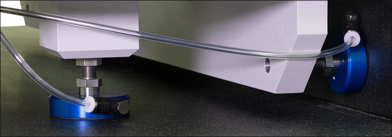
Click to Enlarge
Figure 2.4 VSA series systems include frictionless air bearings that do not wear or require lubrication. A clean source of pressurized air or nitrogen is required.
Air bearings will not wear, do not require lubrication, and do not generate any particulates during use, and thus will require less long-term maintenance. Air bearings are not recommended for unclean environments where dust, dirt, debris, or other fluids may be present. They will also require a source of clean, pressurized air or nitrogen. Periodically lubricating the mechanical bearings and rails on the base systems starting with VSM is recommended.
Click to Enlarge
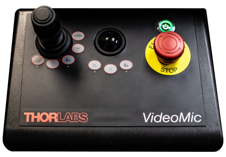
Figure 2.3 Each control panel includes a joystick and trackball for control. The trackball provides a superior feel for smaller, precise movements.
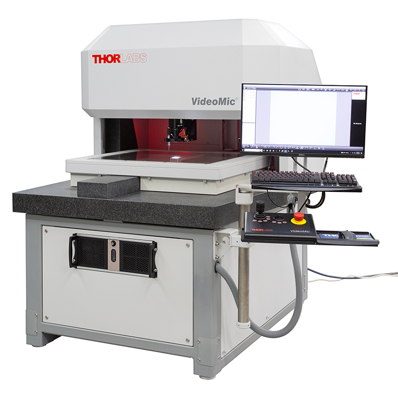
Ergonomic Workstation Design
Each VideoMic system includes a workstation that can be rotated or vertically adjusted for most operator heights (see Figure 2.2). The workstation has a 24" touchscreen monitor, keyboard, mouse, and control panel. Note that the touchscreen functionality is available only when using the M3 metrology software. The control panel, shown in detail in Figure 2.3, includes a joystick and trackball to manually position the stage and camera, an emergency stop switch, a power button to turn the entire system on or off, two sets of three buttons to configure the actions of the joystick or trackball, and enter/ok buttons for selecting data.
Joystick and Trackball
The joystick and trackball can both be used at any time to control the motion of the stage and the camera system mounted on the gantry. When to use one or the other is operator dependent; however, the trackball is designed to minimize the signal delay between its movement and the system's response, allowing operators to have a high level of precise control over their actions. The joystick can be configured for two or three axis adjustments. If a three-axis joystick is chosen, rotating the handle left or right will translate the Z-axis position of the camera assembly.
Control Buttons
A set of three equivalent control buttons are included under both the joystick and track ball. From left to right these are a Z-axis toggle, axis lock, and fine position toggle. The light under each will turn green when a specific button is active. The Z-axis toggle will switch the joystick or trackball function from X/Y to Z. If a three-axis joystick is chosen this will only affect the trackball. The axis lock button is used to toggle between single-axis linear motions. The fine position toggle reduces the responsivity of the joystick and trackball to aid in fine positioning of the system. The enter and ok buttons are used to quickly access the software controls, allowing operators to quickly select data points (measurement positions) and create inspection protocols.
Emergency Stop
This button will cut power to the entire machine and should only be used in case of emergency.
Exploring the Options?
Thorlabs' Multisensor Video Systems are customized to meet the demanding needs of your application. If you do not see a product or specification that you require or you are looking for assistance selecting a system, please contact me. Our Measurement Systems Team is happy to help and can provide system recommendations based on your needs.
Ike Jariel
General Manager
Thorlabs Measurement Systems
Base Systems Specifications
Our Video Measurement Systems come in five base system sizes. All are available with air bearings and linear motors as a standard, except for the VSM463 and VSM713, which include ball-bearings and a servo motor. The specifications specific to the air bearings are highlighted in green.
For complete specifications for all of the ways that Thorlabs' video measurement systems can be customized, please see the Video Configurations and Accessories tabs or contact us using the "Contact Me" link.
| Table 3.1 VideoMic® Base Systems Specifications | |||||||
|---|---|---|---|---|---|---|---|
| Base System Item #a | VSA463 | VSM463 | VSA713 | VSM713 | VSA963 | VSA1273 | |
| XYZ Control | |||||||
| Stage Bearings | Air | Mechanical | Air | Mechanical | Air | ||
| Stage Motors | Linear | Servo | Linear | Servo | Linear | ||
| Measurement (Travel) Range |
X-Y | 460 mm x 305 mm (18" x 12") |
711 mm x 610 mm (28" x 24") |
965 mm x 760 mm (38" x 30") |
1270 mm x 915 mm (50" x 36") |
||
| Z | 200 mm (8") | ||||||
| Accuracyb | X-Y (E2) |
(1.5 + 5L/1000) µm | (2.5 + 5L/1000) µm | (1.5 + 5L/1000) µm | (2.5 + 5L/1000) µm | (1.5 + 5L/1000) µm | |
| Z (E1) |
(1.5 + 5L/1000) µm | ||||||
| Velocity | X-Y | ≤760 mm/s | |||||
| Z | ≤150 mm/s | ||||||
| Repeatability | Z | ±3 µm at High Magnification | |||||
| Granite | Flatness | ≤5 µm (Over Any 700 mm Area) | |||||
| Roughness | Ra0.4 (Equivalent to RMS16) | ||||||
| Waviness | ≤1 µm / 100 mm x 100 mm | ||||||
| Unit Dimensions | |||||||
| Footprint | Width | 40" (102 cm) | 50" (127 cm) | 60" (152 cm) | 85" (216 cm) | ||
| Depth | 40" (102 cm) | 62" (157 cm) | 67" (170 cm) | 75" (191 cm) | 92" (234 cm) | ||
| Total Height | 68" (173 cm) | 73" (185 cm) | 76" (193 cm) | ||||
| Approximate System Weight (Crated / Uncrated) |
2300 lbs (1000 kg) / 1600 lbs (700 kg) | 3600 lbs (1600 kg) / 2700 lbs (1200 kg) | 4500 lbs (2000 kg) / 3500 lbs (1600 kg) | 6600 lbs (3000 kg) / 5400 lbs (2400 kg) | |||
| Approximate Footprint Overhangc | Control Station |
Up to 25" (64 cm) | |||||
| Top Clearance | Allow for Approximately 48" (122 cm) for Servicing | ||||||
| Rear Clearance | Allow for Approximately 24" (61 cm) for Servicing | ||||||
| Typical Unit Dimensions | |||||||
| General | |||||||
| Operating Temperature | Range | 20 ± 0.5 °C (67° - 69 °F) | |||||
| Rate | 0.25 °C/hr (0.5 °F/hr) | ||||||
| Relative Humidity (Non-Condensing) |
30% - 80% | ||||||
| Line Voltage | 115 / 230 VAC, 50 / 60 Hz, Single Phase, 1.0 kW | ||||||
| Air Supply (Air Bearings Only) |
Velocity | 85 L/m (3 CFM) Dry Air |
- | 85 L/m (3 CFM) Dry Air |
- | 85 L/m (3 CFM) Dry Air |
|
| Pressure | 7 - 8.25 Bar (100 - 120 PSI) |
- | 7 - 8.25 Bar (100 - 120 PSI) |
- | 7 - 8.25 Bar (100 - 120 PSI) | ||
Customize Your Video System
Exploring the Options?
Our base systems can be customized to meet the needs of your application. If you do not see a product or specification that you require or you are looking for assistance selecting a system, I'd be pleased to provide system recommendations based on your needs.
Ike Jariel
General Manager
Measurement Systems
A customized VideoMic® multisensor video measurement system requires the selection of surface and/or profile lights, a camera, a zoom lens system, and a metrology software package. Click on the expandable sections to browse all of our options to customize your system.
Lighting Options (Click to Expand)
Click for Details
Figure 4.2 Each Lighting Option Shown Installed on Thorlabs' VideoMic System
LED Lighting Options
- Ring Light for Surface Illumination
- Coaxial Light for Surface Illumination with Reduced Reflections
- Quadrant Light for Dark Field Illumination and Variable Angle of Incidence
- Rear Light for Profile Illumination
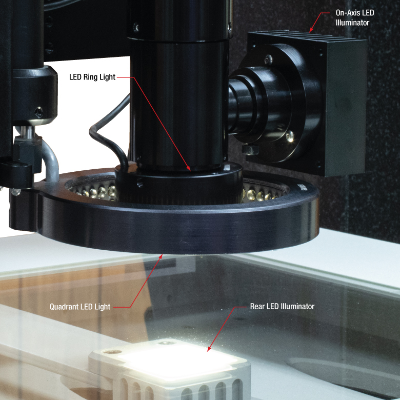
Each VideoMic® Video Measuring System can be customized with any combination of surface and/or profile lights: Ring, Coaxial, Quadrant, and Rear. Each LED-based lighting option has a lifetime greater than 10 000 hours. All lights are controlled through the software, either manually or programmatically as part of an inspection routine. When the lights are adjusted manually in the software, they are adjusted one at a time. A close-up of each light mounted on a video system can be seen in Figure 3.2. For assistance selecting lighting options or for questions, please contact TMS-Sales@thorlabs.com.
Surface Lights
Surface lights include our ring, coaxial, and quadrant light fixtures. The ring light has 40 LEDs and is mounted to the end of the zoom lens. This makes it ideal for illuminating the surface features of a part under inspection. For on-axis lighting, which is ideal for imaging highly reflective surfaces and for eliminating shadows, we offer a coaxial light that mounts to the side of our 6.5X or 12X zoom lens. This will require a zoom lens that includes a coaxial input.
Our quadrant light has 96 LEDs that are mounted around its 92 mm (3.63") inner diameter. This allows the LEDs to illuminate at a shallow angle to the surface, minimizing glare. The quadrant light is always mounted alongside the zoom lens system, as shown in Figure 4.2 . It can be fixed in that location, or motorized so that it can be translated along the Z axis independently from the camera and lens system.
Profile Light
Our profile light is situated below the glass on the stage and is connected to the X axis of travel, i.e. it moves with the camera. The profile light's intensity can be controlled directly through the metrology software. This light is required to perform many of the functions supported by our video systems, including edge detection, through-bore detection, and viewing transparent media.
| Lighting Options | Ring | Coaxial | Quadrant | Profile |
|---|---|---|---|---|
| Lighting Style | Top | Top | Top | Bottom |
| Angle of Incidence (AOI) | Off-Axis, High AOI | On-Axis | Off-Axis, Low AOI | N/A, Profile Light |
| Translationa |
N/A | N/A | Optional Z-Axis | N/A |
| LED Control | Manual or Programmatic Software Control | |||
| Applications | Near Coaxial Illumination Near Uniform Illumination Reduce Shadow Effects Surface Feature Analysis |
Reduce Reflections Shadow-Free Image Highly Reflective Objects Surface Feature Analysis |
Dark Field Illumination Edge Illumination Directional Illumination Surface Feature Analysis |
Profile Lighting Tapped Holes and Bores Etching and Engravings Transparent Media |
| Light Source | LED | |||
| Color | White, 5500 K | |||
| Lifetime | >10 000 hr | |||
Camera Options (Click to Expand)
| Table 4.3 Specifications | ||
|---|---|---|
| Camera Options | 1.3 MP | 5 MP |
| Sensor Type | onsemi PYTHON 1300 CMOS Color: NOIP1SE1300A-QDI | Sony IMX264 CMOS Color: IMX264LQR-C |
| Pixels (H x V) |
1280 x 1024 | 2456 x 2054 |
| Imaging Area (H x V) |
6.14 mm x 4.92 mm | 8.47 mm x 7.09 mm |
| Pixel Size | 4.80 µm x 4.80 µm | 3.45 µm x 3.45 µm |
| Optical Format | 1/2" | 2/3" |
| Frame Rate | 88 fps | 22 fps |
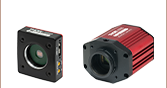
Camera Options
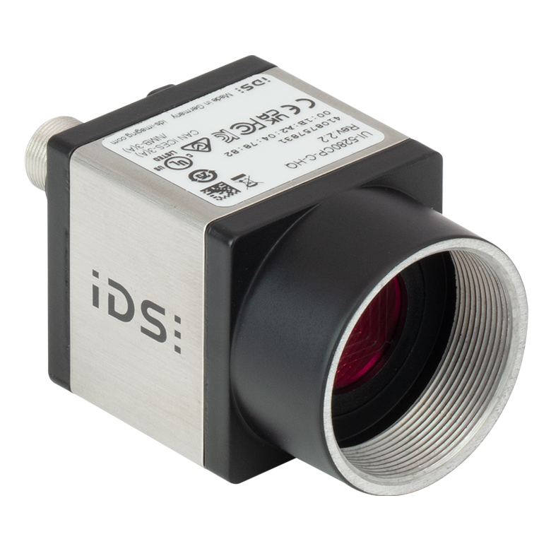
- 1.3 MP CMOS Color Camera with 1/2" Optical Format
- 5 MP CMOS Color Camera with 2/3" Optical Format
Thorlabs offers a 1.3 MP and a 5 MP CMOS color camera for use in our VideoMic Systems. The 1.3 MP option offers a high-quality onsemi®* PYTHON 1300 sensor with a 1/2" optical format and speeds up to 88 fps. It is ideal for quickly imaging a large number of products fixed on the video stage. The 5 MP option offers a high 2456 x 2054 pixel resolution Sony®† IMX264LQR-C sensor with a 2/3" optical format, making it ideal for detailed inspections of small items. The 5 MP camera will operate at a slower, 22 fps speed and will have an increased FOV, comparatively.
Specifications for our 1.3 MP and 5 MP cameras can be found in Table 4.3.
For assistance selecting the appropriate camera for your application, please contact TMS-Sales@thorlabs.com.
*onsemi® is a registered trademark of Semiconductor Components Industries, LLC.
†Sony® is a registered trademark of the Sony Group Corporation.
Click to Enlarge
Figure 4.4 5 MP Camera
Click to Enlarge
Click Here for Full-Size Image
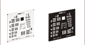
Figure 4.5 Thorlabs' P800K 800 μm Pinhole Image Captured at 0.7X with a 5 MP Camera in Our Video Measurement System
Click to Enlarge
Click Here for Full-Size Image
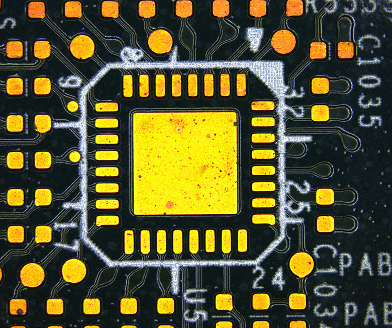
Figure 4.6 Printed Circuit Board Image Captured at 0.7X with a 5 MP Camera in Our Video Measurement System
Zoom Lens System Options (Click to Expand)
Click to Enlarge
Figure 4.8 Transmission does not include an auxiliary lens or extension tube. An AR coating minimizes reflections in the visible spectra (about 400 - 700 nm).
Click for Details
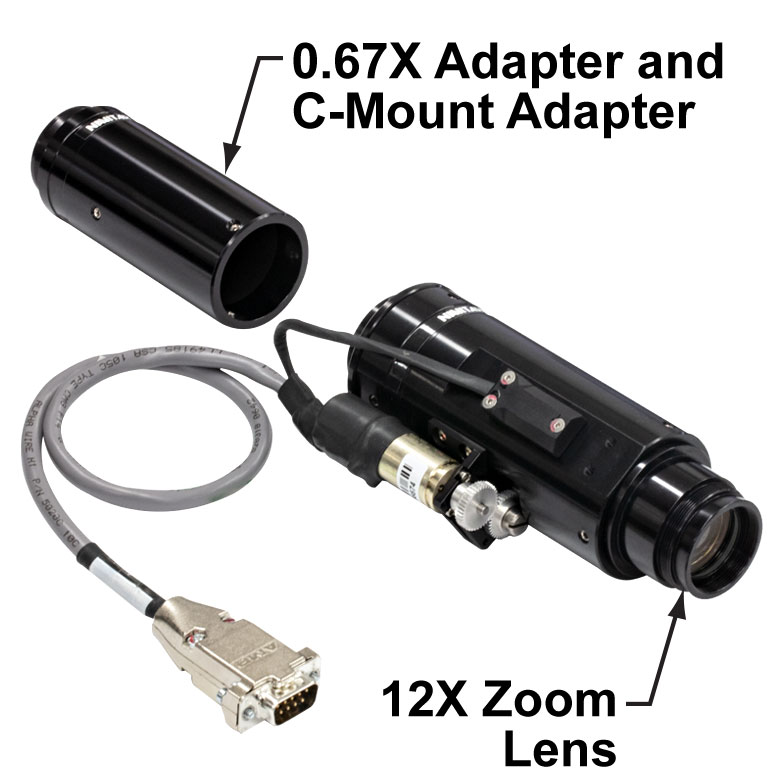
Figure 4.7 Motorized Zoom Lens System Shown with 12X Zoom Lens and 0.67X Auxiliary Lens
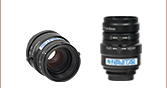
Zoom Lens System Options
- 6.5X Optical Zoom Lens System
- 0.25X to 2.0X Auxiliary Lenses
- 0.5X to 5X Extension Tubes
- 12X Optical Zoom Lens System
- 0.25X to 2.0X Auxiliary Lenses
- 0.5X to 3.3X Extension Tubes
- Each can be Equipped with a Coaxial Light Input Port
A zoom lens system consists of three modules: the zoom lens, an auxiliary lens, and an extension tube. The zoom lens provides the base 6.5X or 12X optical magnification. The auxiliary lens is attached to the end of the zoom lens housing to increase or decrease the base magnification, while the extension tube positions the camera at the image plane with or without additional magnification.
Each module can be viewed in the first three columns of Tables 4.9 and 4.10. Specifications, including system magnification and field of view, can be found by reading horizontally across from your selection. Note that the field of view is dependent on the camera format being used.
The most popular system options are highlighted in green. Please see our bi-telecentric lens options below and contact TMS-Sales@thorlabs.com if a telecentric zoom lens is needed.
Zoom Lenses with Coaxial Light Input
Specifications for a 12X and 6.5X system with a side-mounted coaxial light input will be the same as those in Tables 4.9 and 4.10; however, the transmission may drop slightly due to the additional beamsplitter the light must pass through. Additionally, the 0.25X, 0.5X, and 0.75X auxiliary lenses are not compatible with this zoom lens version. The internal coaxial light will illuminate a circular area of 14 mm and 11 mm in diameter for the 12X and 6.5X zoom lenses, respectively. Any field of view (FOV) larger than these values will have darkened corners.
| Table 4.9 6.5X Zoom Lens System Specifications |
|---|
| Table 4.10 12X Zoom Lens System Specifications |
|---|
Bi-Telecentric Lens Options (Click to Expand)
| Table 4.12 Bi-Telecentric Lens Specifications | ||
|---|---|---|
| Bi-Telecentric Lens Options | 0.128X | 0.243X |
| Magnification Tolerance | ±1% | |
| Working Distancea | 179.0 mm | 97.9 mm |
| C-Mount Flange Focal Distance | 17.5 mm | |
| Image Diagonal | 11 mm (2/3" Format) | |
| Max Distortion | 0.16% | 0.10% |
| Depth of Fieldb | ±15 mm | ±11 mm |
| System f/# | f/7 | f/8 |
| Field of View (2/3" Format Sensor)c | 85.9 mm | 45.3 mm |
| Telecentricity | 0.03° | |
| Modulation Transfer Function (MTF)d | >55% | >51% |
| Coherent Transfer Function (CTF)d | >67% | >63% |
| Image NA | 0.071 | 0.062 |
| Object NA | 0.0091 | 0.015 |
| Average Transmittancee | 94% Over 460 - 630 nm | |
Bi-Telecentric Lens Options
- 0.128X Bi-Telecentric Lens for Sensor Formats Up to 2/3" (Item # MVBT2313)
- 0.243X Bi-Telecentric Lens for Sensor Formats Up to 2/3" (Item # MVBT2324)
- Provide Constant Magnification Independent of Object Location
Thorlabs offers its own line of bi-telecentric lenses for machine vision applications that can be used as an alternative to a 6.5X or 12X zoom lens system. These lenses offer magnification in both image and object space that is independent of distance (within the depth of field) or the position in the field of view. This attribute is ideal for machine vision applications: when measuring dimensions, a telecentric lens will yield the same measurement regardless of changes in object distance or position.

Click to Enlarge
Figure 4.11 0.128X Bi-Telecentric Lens
Objective Options (Click to Expand)
Click to Enlarge
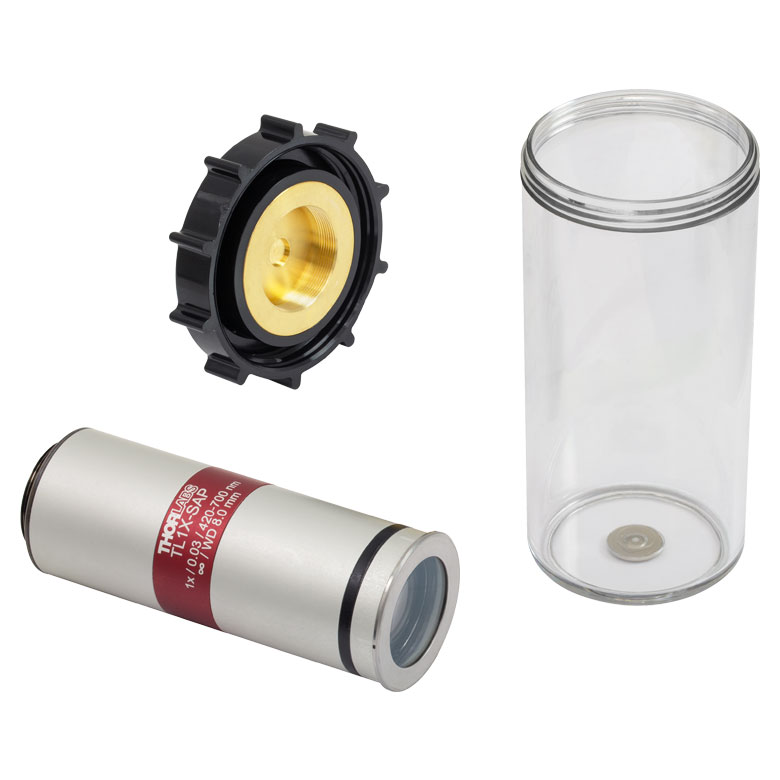
Figure 4.13 Thorlabs' TL1X-SAP 1X Objective with Included Case
Long-Working-Distance Objective Options
- 1X, 5X, 10X, 20X, or 50X Magnification
- Variety of Options to Support Use from 240 nm to 656 nm
- Suitable for Brightfield Observation
Thorlabs offers apochromat objectives with 1X, 5X, 10X, 20X, or 50X magnification that can be installed as an attachment to our 6.5X or 12X zoom lens systems. They are designed to be used with a 200 mm focal length tube lens and feature a flat field of focus and chromatic correction in the visible range. The long working distance provides a wide space between the lens surface and the object, making them ideal for machine vision applications. The TL1X-SAP 1X Objective also offers a telecentric design with a removable waveplate to minimize back reflections.
Each objective is engraved with its class, magnification, numerical aperture, a zero (noting that it is to be used to image a sample without a cover glass), and the tube lens focal length for which the specified magnification is valid. If the case shipped with each of these objectives is lost or broken, Thorlabs offers an objective case (Item #s OC2M26 and OC24) that can be used as a replacement.
For additional information about these objectives, including a tutorial that defines the properties of an objective, please see our complete presentation.
| Table 4.14 Objectives Specifications | ||||||||||
|---|---|---|---|---|---|---|---|---|---|---|
| Item # | Wavelength Range | Ma | WD | EFL | NA | EP | Typical Transmission | OFN | PFL | AR Coating Reflectance |
| TL1X-SAPb | 420 - 700 nm | 1X | 8.0 mm | 200 mm | 0.03 | 12.1 mm | Raw Data |
22 | 95.0 mm | Ravg < 0.5% per Surface @ 0° AOI (420 - 700 nm) |
| MY5X-802B | 436 - 656 nm | 5X | 36.5 mm | 40 mm | 0.14 | 11.2 mm | 24 | 95 mm | Not Available | |
| MY10X-803 | 10X | 34.0 mm | 20 mm | 0.28 | 11.2 mm | |||||
| MY20X-804 | 20X | 20.0 mm | 10 mm | 0.42 | 8.4 mm | |||||
| MY50X-805 | 50X | 13.0 mm | 4 mm | 0.55 | 4.4 mm | |||||
Software (Click to Expand)
Click to Enlarge
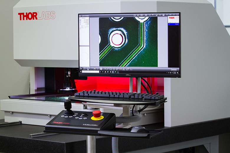
Figure 4.15 M3 Software GUI
M3 MetLogix®a Metrology Software
- Program custom routines that control movement, lighting, fixtures, and more.
- The Microsoft Windows® environment is used with on-line help to ease training.
- Programs can be automatically created from CAD data or by recording steps while manually measuring a part.
- Enhanced video edge detection (VED) for selective feature measurement.
- Versatile video edge detection tools such as linewidth, circle, center-of-mass, and buffer that speed the measuring process.
- The system reports position and size of features, allowing optimization of the user’s fabrication process.
- Tolerancing to Cartesian, as well as True Position, LMC, and MMC is provided.
Each VideoMic® Video Measuring System includes the M3 MetLogix software package. The software supports 2-axis measurements in X and Y, as well as precision Z-axis measurements. Please note that it cannot obtain volumetric 3-axis measurements. Video edge detection (VED) tools permit the calculation of radius, diameter, distance, and angle measurements, as well as auto-alignment of parts under inspection. Unit conversions and nonlinear error corrections are standard.
Integral motion control software permits automatic and semi-automatic measurement and inspection routines as well as graphic interactive part mapping. The system takes full advantage of touch-screen capabilities thereby enhancing the learning process. This package is required if using our triangulation laser sensor.
- MetLogix is a registered trademark of MetLogix, Inc.
Optional Accessories
Exploring the Options?
Our base systems can be customized to meet the needs of your application. If you do not see a product or specification that you require or you are looking for assistance selecting a system, I'd be pleased to provide system recommendations based on your needs.
Ike Jariel
General Manager
Thorlabs Measurement Systems
Thorlabs' video measuring machines can be enhanced with the addition of tactile touch-trigger probes and non-contact laser probes in a single machine. This multisensor capability increases the flexibility of the system, allowing it to precisely measure and inspect the most complex parts without the need to switch systems. Our selection of accessories can be viewed by clicking on the expandable sections.
Renishaw® Tactile Probe Options (Click to Expand)
| Probe Body Options | ||
|---|---|---|
| Series | TP20 | TP200 |
| Sensor Type | Kinematic | Strain Gauge |
| Application | Auto or Manual CMM, Suitable for Most Applications | Auto or Manual CMM with High Accuracy |
| Renishaw Stylus Range |
M2 Threaded | |
Click to Enlarge
Figure 5.3 A Renishaw TP20 Kinematic Touch-Trigger Probe Shown Mounted Within a Thorlabs Video System

Click to Enlarge
Figure 5.2 A Selection of LF, SF, and MF Probe Module and M2 Styli with Varying Tip Styles
Renishaw®* Tactile Probe Options
- TP20 Series 3-Axis, Kinematic Touch-Trigger Probes
- TP200 Series 3-Axis, Strain Gauge Touch-Trigger Probes
Thorlabs' video measuring systems are compatible with most Renishaw TP20 and TP200 series
TP20 Series
The TP20 series design is modeled on a spring-loaded kinematic arrangement where three rods are each resting within two ball bearings that are spaced approximately 120° apart. When the stylus contacts a part, an internal spring will resist the slight force but still allow the ball seats to deflect and pivot. This deflection will trigger a signal to the system to stop the measurement and record the signal.
TP200 Series
The TP200 series uses a similar kinematic mechanism as the TP20 series to retain the stylus; however, it does not utilize the mechanical movement to trigger an event. Instead, a set of silicon-based strain gauges is placed above the kinematic mechanism. These gauges will measure the force of the stylus in any direction and trigger a measurement once the force surpasses a preset value.
Specifications for a selection of Renishaw's probe modules can be found in Tables 5.4 and 5.5. Please contact TMS-Sales@thorlabs.com for help customizing a system or to inquire about other options.
*Renishaw is a registered trademark of Renishaw plc.
| Table 5.4 TP20 Series Probe Options and Specificationsa | ||||||||||||
|---|---|---|---|---|---|---|---|---|---|---|---|---|
| Moduleb | Sense Direction | Pre-Travel Variation |
Unidirectional Repeatability |
Trigger Force (N) (Stylus Lengthc) |
Overtravel Force (N) (Stylus Lengtha) |
Overtravel Displacement |
Repeatability of Stylus Changing |
|||||
| XYb | Z | XY | +Z | -Z | XY (deg.) | +Z (mm) | -Z (mm) | |||||
| Low Force (LF) | ±X, ±Y, +Z | ±0.60 µm | ±0.35 µm | 0.055 | 0.65 | 0.09 | 1.15 | N/A | ±14 | 3.1 | N/A | Motorized: ±0.50 μm Manual: ±1.00 μm |
| Standard Force (SF) | ±0.80 µm | ±0.35 µm | 0.08 | 0.75 | 0.2 - 0.3 | 3.5 | N/A | 4 | ||||
| Medium Force (MF) |
±1.00 µm | ±0.50 µm | 0.10 (25 mm) |
1.9 (25 mm) |
0.2 - 0.4 (25 mm) |
7 (25 mm) |
N/A | 3.7 | ||||
| Extended Force (EF) | ±2.00 µm | ±0.65 µm | 0.10 (50 mm) |
3.2 (50 mm) |
0.2 - 0.5 (50 mm) |
10 (50 mm) |
N/A | 2.4 | ||||
| 6 Way (6W) | ±X, ±Y, ±Z | ±1.50 µm | ±1.00 µm | 0.14 | 1.60 | 0.25 | 2.5 | 9 | 4.5 | 1.5 | ||
| Table 5.5 TP200 Series Probe Options and Specifications | ||||||||||||
|---|---|---|---|---|---|---|---|---|---|---|---|---|
| Moduleb | Sense Direction |
Unidirectional Repeatability |
XY Form Measurement Deviation |
XYZ Form Measurement Deviation |
Trigger Force (N) | Overtravel Forcea (N) | Repeatability of Stylus Changing |
|||||
| Trigger 1 | Trigger 2 | Trigger 1 | Trigger 2 | Trigger 1 | Trigger 2 | XYc | Z | XY | Z | |||
| Low Force (LF) | ±X, ±Y, ±Z | ±0.40 µm | ±0.50 µm | ±0.80 µm | ±0.90 µm | ±1 µm | ±1.4 µm | 0.02 | 0.07 | 0.1 - 0.15 | 1.6 | Motorized: ±0.50 μm Manual: ±1.00 μm |
| Standard Force (SF) | 0.2 - 0.4 | 4.9 | ||||||||||
| Extended Overtravel (EO) |
0.2 - 0.4 | 4.9 | ||||||||||
Laser Sensor (Click to Expand)
Triangulation Displacement Laser Sensor
Thorlabs offers a triangulation displacement sensor (TDS), which provides high-precision distance, surface contour, 2D profile, and thickness measurements. It can also be used for quickly getting an image into focus.
The TDS determines the target's position by measuring the reflected light from the target's surface using an internal CCD detector. This light collection is not co-linear, i.e. there is a fixed angle between the beam output and the collection optic. This design allows the sensor to have a larger standoff.
The TDS does not use an objective, but is chosen by its direct measurement range. Please contact TMS-Sales@thorlabs.com for help in selecting system options or to inquire about other options.
Video 5.7 Triangulation laser being used to measure the surface flatness of Thorlabs optic mount's front plate.
Click to Enlarge
Figure 5.6 Triangulation Laser Sensor
| Triangulation Displacement Sensor Specifications | |||
|---|---|---|---|
| Measuring Rangea | 25 mm | 50 mm | |
| Measuring Range Spread | Start (SMR) | 25 mm | 35 mm |
| Mid (MMR) | 27.5 mm | 60 mm | |
| End (EMR) | 50 mm | 85 mm | |
| Linearityb | ≤ ±0.08% | ≤ ±0.08% | |
| Repeatability at Measuring Rate | 1 µm | 2 µm | |
| Measuring Rate | 2 kHz | ||
| Spot Diameter (±10%) | SMR | 100 x 140 µm | 90 x 120 µm |
| MMR | 120 x 130 µm | 230 x 240 µm | |
| EMR | 390 x 500 µm | 630 x 820 µm | |
| Minimum | 55 x 50 µm | 70 x 65 µm | |
| Laser Power | <1 mW | ||
| Laser Color | Red (670 nm) | ||
| Laser Safety Class | Class 2 in Accordance with DIN EN 60825-1 : 2008-05 |
||
Confocal Chromatic Sensor Options (Click to Expand)
µE Micro-Epsilon®* Confocal Chromatic Sensors
- IFS2405 Series Sensors
- Highest Distance Measurement Accuracy
The Confocal Chromatic Sensors from µE Micro-Epsilon®* have the highest performance in distance measurement for both static and dynamic measurements. These sensors use polychromatic white light in combination with controlled chromatic aberrations in the optical system, so that different colors from the light focus at different focal depths. After calibration of the focal distance versus the wavelength, a confocal measurement of the reflected light's spectrum allows the distance to the part being measured to be determined. Please contact TMS-Sales@thorlabs.com for help in selecting system options.
| Table 5.8 Confocal Chromatic Sensor Specifications | ||||||||
|---|---|---|---|---|---|---|---|---|
| Measuring Range | 0.3 mm | 1 mm | 3 mm | 6 mm | 6 mm @ 90° | 10 mm | 28 mm | 30 mm |
| Measurement Specifications | ||||||||
| Approximate Start | 6 mm | 10 mm | 20 mm | 63 mm | 41 mmf | 50 mm | 220 mm | 100 mm |
| Static Resolutiona | 4 nm | 8 nm | 15 nm | 34 nm | 36 nm | 130 nm | 93 nm | |
| Dynamic Resolutionb | 18 nm | 38 nm | 80 nm | 190 nm | 204 nm | 747 nm | 530 nm | |
| Displacement and Distance Linearityc | < ±0.1 µm | < ±0.25 µm | < ±0.75 µm | < ±1.5 µm | < ±2 µm | < ±7 µm | < ±6 µm | |
| Thickness Linearityc | < ±0.2 µm | < ±0.5 µm | < ±1.5 µm | < ±3 µm | < ±4 µm | < ±14 µm | < ±12 µm | |
| Light Spot Diameter | 6 µm | 8 µm | 9 µm | 31 µm | 16 µm | 60 µm | 50 µm | |
| Measuring Angle (Max)d | ±34° | ±30° | ±24° | ±10° | ±17° | ±5° | ±9° | |
| Numerical Aperture (NA) | 0.60 | 0.55 | 0.45 | 0.22 | 0.30 | 0.10 | 0.20 | |
| Target Thickness (Min)e | 0.015 mm | 0.05 mm | 0.15 mm | 0.3 mm | 0.5 mm | 0.10 mm | 0.20 mm | |
| Target Material | Reflective, Diffuse, and Transparent Surfaces (e.g. Glass) | |||||||
| General Specifications | ||||||||
| Connection | Optical Fiber via FC Socket, Length 3 m, Extendable up to 50 m, Bending Radius: Static 30 mm, Dynamic 40 mm | |||||||
| Operating Temperature | 5 to 70 °C | |||||||
| Storage Temperature | -20 to 70 °C | |||||||
| Shock (DIN EN 60068-2-27) | 15 g / 6 ms in XY Axis, 1000 Shocks Each | |||||||
| Vibration (DIN EN 60068-2-6) | 2 g / 20 - 500 Hz in XY Axis, 10 Cycles Each | |||||||
| Protection Class (DIN EN 60529) | IP64 (Front) | |||||||
| Material | Aluminum Housing, Glass Lenses | |||||||
*µE Micro-Epsilon is a registered trademark of Micro-Epsilon-Messtechnik GmbH & Co. KG
Fixturing Options (Click to Expand)
Fixturing Component Options
- Motorized Rotation Mounts and Stages
- Hinged Glass Platen or Pneumatic Hinged Glass Platan
Thorlabs offers numerous options for fixing an object in place during inspection with our video coordinate measuring machines (video CMMs). Fixturing is the process of securing an object prior to measurement. Doing so allows for repeatable, accurate, and fast measurement of a large number of items from a production run.
Motorized Rotation Mounts and Stages
A wide selection of motorized rotation mounts and stages are available that can be mounted directly to our fixture plates. This would facilitate the creation of a motorized, modular fixturing system that could repeatably rotate and position items quickly and accurately.
Hinged Glass Platen or Pneumatic Hinged Glass Platan
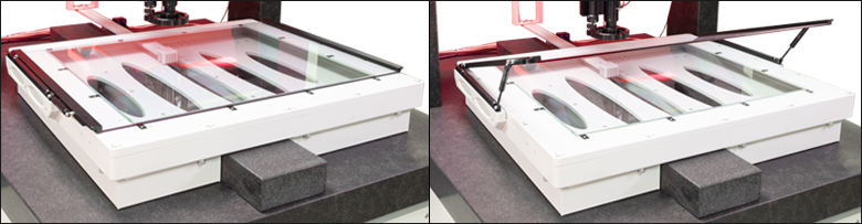
A hinged glass platen or pneumatic hinged glass platen can be added to any stage to secure smaller objects or circuit boards up to 0.20" (5.1 mm) thick. The pneumatic version can be configured to automatically open as part of a software routine, whereas the hinged glass platen can only be opened manually by lifting the glass panel. If an automated quadrant light is being used, then the system will be programmed to clear the quadrant light whenever the platen is raised, preventing an unwanted collision. Note that this option is not compatible with a system that has a touch-probe rack installed.
Software and Hardware Upgrades (Click to Expand)
Click to Enlarge
Figure 5.11 System with M3 Software and Touch Monitor
Software and Hardware Upgrades
- Offline Programming and Analysis Software
- Statistical Process Control (SPC) EXCEL-Based®* Software Package
Please contact TMS-Sales@thorlabs.com for questions about any of these options.
Offline Programming and Analysis Software
Additional metrology software licenses are available for offline programming and analysis. Enhance throughput by transferring programming and analysis tasks to an independent computer or computers. This requires additional computer or computers for installing the metrology software and connecting to a license key.
Statistical Process Control (SPC) EXCEL-Based Software Package
This SPC program includes tools and procedures to monitor and control process behaviors, internal system errors, and production issues. It is an EXCEL-based package that can be integrated into any video system.
*EXCEL is a registered trademark of Microsoft Corporation.
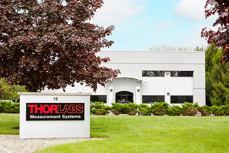
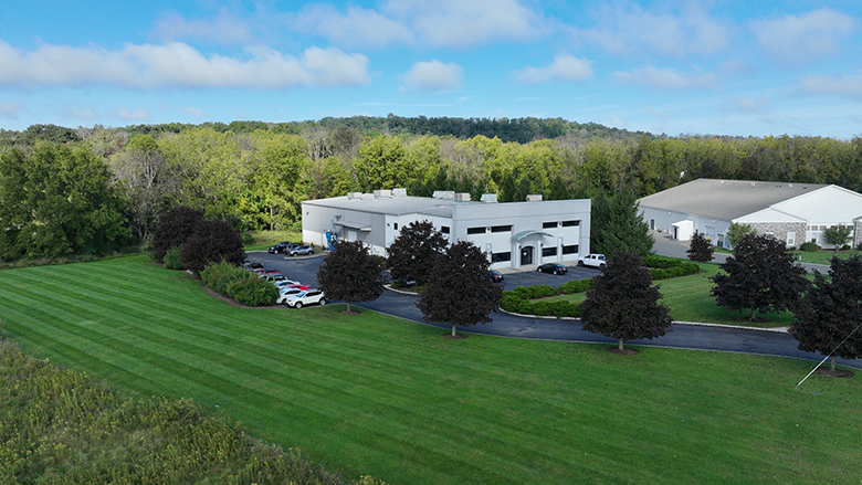
VideoMic® System Live Demonstrations at Our Sparta, New Jersey, USA Location
Send Your Samples or Bring Your Samples to Us
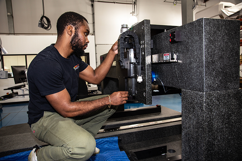
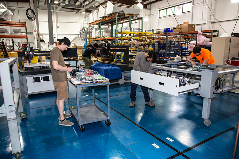
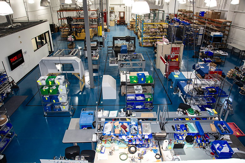
- Thorlabs Measurement Systems (TMS) is located in Sparta, New Jersey, and has a demo room with VideoMic systems for customer samples, in addition to our warehouse and machine room.
- Our VideoMic systems are built at our Sparta location, from parts produced mainly in the USA.
- Send us your samples, and we will do an online live demonstration with you and send your sample data to you.
- Or bring your samples to us, and we will perform the demonstration on-site with you.
- During your demonstration, you can tour our TMS facility, where our employees will build your system.
Contact TMS Sales if you are interested in sending us your samples or bringing your samples to us for a live demonstration of the features and capabilities of our VideoMic systems for your video CMM needs, or if you are interested in a custom VideoMic system configuration for your application. We can arrange custom demonstrations so that you can see what your sample data will look like when measured with a custom configuration.
| Posted Comments: | |
| No Comments Posted |