 Products Home / Active Optical Devices / Optical Amplifiers / Ytterbium-Doped Fiber Amplifiers (YDFA), 1050 nm
Ytterbium-Doped Fiber Amplifiers (YDFA), 1050 nm
- Saturation Output Power of >19 dBm or >25 dBm
- Single Mode or Polarization-Maintaining Output
- Low-Noise, High-Gain Performance
- Simple, Turnkey Operation or Remote Control with USB
YDFA100S
Single Mode YDFA,
>19 dBm Output Power
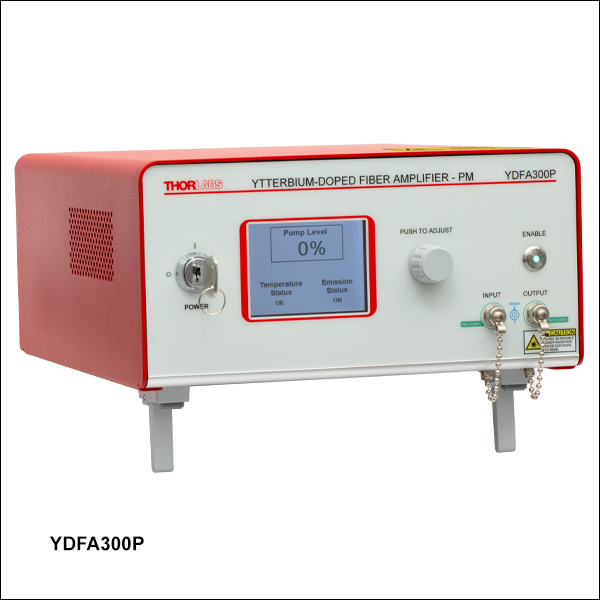
YDFA300P
Polarization-Maintaining YDFA,
>25 dBm Output Power


Please Wait
| Table 1.1 Key System Specificationsa | ||||
|---|---|---|---|---|
| Item # | YDFA100S | YDFA100P | YDFA300P | |
| Operating Wavelength Range | 1025 - 1075 nm | 1030 - 1070 nmb | ||
| Saturated Output Powerc |
>19 dBm @ 3 dBm Input Power | >25 dBm @ 3 dBm Input Power | ||
| Small Signal Gainc |
>22 dB @ -20 dBm Input Power | >28 dB @ -5 dBm Input Power | ||
| Noise Figurec | <8 dB @ -20 dBm Input Power | <6 dB @ -3 dBm Input Power | ||
| Minimum Input Power | N/A | -5 dBmd | ||
| Polarization Extinction Ratioc | N/A | >20 dB | >20 dB | |
| Polarization-Dependent Gain | <0.3 dB | N/A | N/A | |
| Feature Comparison | ||||
|---|---|---|---|---|
| Item # | YDFA100S | YDFA100P | YDFA300P | |
| Front Panel Interface |  |
|
||
| Constant Current Mode | |
|
||
| Constant Power Mode | - | a |
||
| Constant Gain Mode | - | a |
||
| Remote Control Interface | USB | |||
Features
- Operating Wavelength Range:
- 1025 - 1075 nm (Item #s YDFA100S and YDFA100P)
- 1030 - 1070 nm (Item # YDFA300P)
- Available in Three Models (See Table 1.1)
- Ideal for Use as a Preamplifier or Booster Amplifier for Ultrafast and CW Applications
- Low Dispersion Design for Ultrafast Pulse Applications (Item #s YDFA100S and YDFA100P)
- Front Panel Controls and Remote Control Over USB
- Constant Current Mode Operation (Item #s YDFA100S and YDFA100P)
- Constant Current, Constant Power, and Constant Gain Operation Modes (Item # YDFA300P)
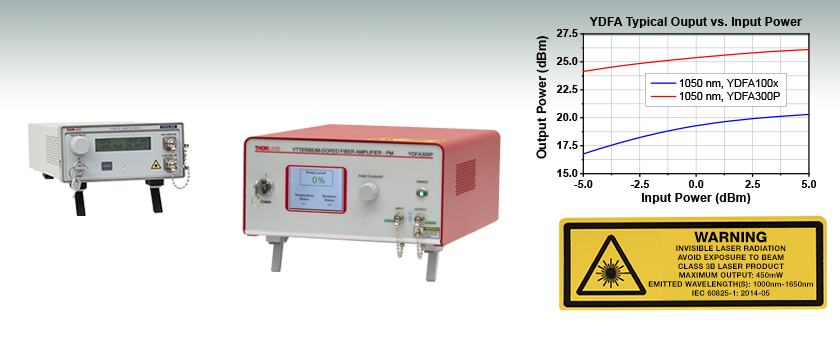
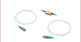
Thorlabs' Core-Pumped Ytterbium-Doped Fiber Amplifiers (YDFAs) provide high small signal gains and output powers in a compact, turnkey benchtop package with FC/APC (2.0 mm narrow key) input and output connectors. Our YDFAs are available in two output powers, >19 dBm (20 dBm Typical) or >25 dBm, which correspond to the YDFA100x amplifiers and YDFA300P amplifier, respectively. In order to support applications involving femtosecond pulses, our YDFA100x devices are engineered to impart minimal dispersion; see the fs Pulse Amplification tab for more information. The YDFA300P amplifier, which provides higher output power and higher gain than the YDFA100x devices, is recommended for use as a booster amplifier. For detailed specifications and typical performance graphs, see the Specs and Graphs tabs, respectively.
For additional flexibility, the YDFA100x amplifiers are available in single mode (SM) and polarization-maintaining (PM) models. The YDFA100S SM amplifiers are polarization-insensitive, and the input and output fibers to the amplifier are standard single-mode fiber (HI1060) with <0.3 dB polarization-dependent gain. The YDFA100P and YDFA300P PM amplifiers are polarization sensitive, only amplifying light that is linearly polarized along the slow axis. The input and output fibers of the PM amplifiers are polarization maintaining fiber (PM980-XP) and the connector keys are aligned to the slow axis of the fibers. All models are compatible with FC/APC, 2.0 mm narrow key fiber connectors.
Operation Modes
The gain and output power of YDFA100x amplifiers are determined by the pump current, which can be varied through the instrument's front panel or remotely via a USB Type-B port. The YDFA300P amplifier can operate in three modes, including constant current, constant power, or constant gain operation modes. Constant current mode is available via the instrument front panel or remotely via a USB Type-B port, while constant power and constant gain operation modes are only available through a command-line interface.
For applications that require YDFAs with custom output power, gain, or wavelength range, or for a custom version of the YDFA300P amplifier with single mode fiber, please contact Tech Sales with inquiries. Thorlabs also offers Erbium-Doped Fiber Amplifiers (EDFAs) and Praseodymium-Doped Fiber Amplifiers (PDFAs), which operate in the
Unless otherwise indicated, all values are specified for a CW input beam at 1050 nm.
| Item # | YDFA100S | YDFA100P |
|---|---|---|
| Amplifier Specifications | ||
| Operating Wavelength Range | 1025 - 1075 nm | |
| Saturated Output Power (@ 3 dBm Input Power)a | 19 dBm (Min) 20 dBm (Typical) |
|
| Small Signal Gain (@ -20 dBm Input Power)a | >22 dB | |
| Noise Figure (@ -20 dBm Input Power)a | <8 dB | |
| Output Power Stability (@ 3 dBm Input Power) |
<±2% Over 24 Hours (After 15 Minute Warm-Up, for Ambient Temperature ±2 °C) | |
| Total Absolute Dispersion within Amplifier | <0.2 ps/nm | |
| Laser Class | 3B | |
| Fiber Specifications | ||
| Output Polarization | Random | Linear Aligned to Slow Axis |
| Polarization Extinction Ratio | N/A | >20 dB |
| Polarization-Dependent Gain | <0.3 dB | N/A |
| Return Loss at Input Port | >50 dB | |
| Input / Output Isolation | >20 dB | |
| Input / Output Fiber Type | HI1060 | PM980-XP |
| Input / Output Fiber Connectors | FC/APC Compatible, 2.0 mm Narrow Key | |
| Absolute Maximum Ratings | |
|---|---|
| Absolute Maximum Input Power | 10 dBm |
| Absolute Maximum Output Power | 23 dBm |
| Operating Temperature | 15 to 35 °C |
| Storage Temperature | 0 to 50 °C |
| General Specifications | |
|---|---|
| Input Voltage | 100 - 240 VAC, 50 - 60 Hz |
| Input Power | 20 VA (Max) |
| Fuse Rating | 500 mA |
| Fuse Type | IEC60127-2/III (250 VA, Slow Blow Type "T") |
| Dimensions (W x H x D) | 5.77" x 3.07" x 12.17" (146.5 mm x 77.9 mm x 309.1 mm) |
| Weight | 1.96 kg (4.32 lbs) |
| Connections and Controls | |
| Interface Control | Optical Encoder with Push Button |
| Enable Select | Keypad Switch Enable with LED Indicator |
| Power On | Key Switch |
| Fiber Connectors | FC/APC Compatible, 2.0 mm Narrow Key |
| Input Power Connector | IEC Connector |
| Interlock | 2.5 mm Mono Jack |
| Communications | |
| Communications Port | USB 2.0 Compatible |
| COM Connection | USB Type-B Connector |
| Required Cable | USB Type-A to Type-B Cable (Replacement Item # USB-A-79) |
| Item # | YDFA300P | |
|---|---|---|
| Amplifier Specifications (@ 100% Pump Current Set Point) | ||
| Operating Wavelength Rangea | 1030 - 1070 nm | |
| Saturated Output Powerb,c (@ 3 dBm Input Power) | >25 dBm | |
| Small Signal Gainb (@ -5 dBm Input Power) | >28 dB | |
| Noise Figureb (@ -3 dBm Input Power) | <6 dB | |
| Minimum Input Powerd | -5 dBm | |
| Output Power Stabilitye (Constant Current Mode @ 3 dBm Input Power) | <±2% Over 24 Hours | |
| Output Power Stabilitye (Constant Power Mode @ 3 dBm Input Power) | <±0.5% Over 24 Hours | |
| Total Absolute Dispersion Within Amplifier | <0.4 ps/nm | |
| Laser Class | 3B | |
| Fiber Specifications | ||
| Output Polarization | Linear, Aligned to Slow Axis | |
| Polarization Extinction Ratiob | >20 dB | |
| Return Loss at Input Portb | >50 dB | |
| Input / Output Isolationb | >30 dB | |
| Input / Output Fiber Type | PM980-XP | |
| Input / Output Fiber Connectors | FC/APC Compatible, 2.0 mm Narrow Key |
|
| Absolute Maximum Ratings | |
|---|---|
| Absolute Maximum Input Power | 10 dBm |
| Absolute Maximum Output Power | 26.5 dBm |
| Operating Temperature | 15 to 30 °C |
| Storage Temperature | -10 to 40 °C |
| General Specifications | ||
|---|---|---|
| Input Voltage | 100 - 240 VAC, 50 - 60 Hz | |
| Input Power | 20 W (Max) | |
| Fuse Rating | 2 A, 250 V | |
| Fuse Type | Time-Lag (Slow-Blow) | |
| Fuse Size | 5 mm x 20 mm | |
| Dimensions (W x D x H) |
300.0 mm x 250.0 mm x 122.2 mm (11.81" x 9.84" x 4.81") |
|
| Weight | 3.4 kg (7.5 lbs) | |
Performance Graphs
All YDFA100x amplifier performance graphs are representative of the YDFA100S and YDFA100P devices, and were obtained using a CW input, the maximum pump current of 1000 mA, and the factory pump temperature setting of 25 °C unless otherwise stated. YDFA300P amplifier performance graphs are taken with the maximum pump level. Note that this data reflects the typical performance of our YDFAs, and is presented for reference only. The guaranteed specifications for all models are shown in the Specs tab.
Output Power Scaling
Click to Enlarge
Click for Raw Data
Typical YDFA100x Amplifier Output Power as a Function of Input Power
Click to Enlarge
Click for Raw Data
Typical YDFA100x Amplifier Output Power at 1050 nm as a Function of
Pump Current

Click to Enlarge
Click for Raw Data
Typical YDFA300P Amplifier Output Power as a Function of Input Power
Click to Enlarge
Click for Raw Data
Typical YDFA300P Amplifier Output Power at 1050 nm as a Function of Pump Level
Gain
Click to Enlarge
Click for Raw Data
The typical YDFA100x amplifier gain as a function of the wavelength. The blue-shaded region denotes the specified operating wavelength range.
Click to Enlarge
Click for Raw Data
The typical YDFA300P amplifier gain as a function of the wavelength over the full operating wavelength range (
Noise Figure
Click to Enlarge
Click for Raw Data
The typical YDFA100x amplifier noise figure as a function of the wavelength. The blue-shaded region denotes the specified operating wavelength range.
Click to Enlarge
Click for Raw Data
The typical YDFA300P amplifier noise figure as a function of the wavelength over the full operating wavelength range (
| Table 4.1 Simulation Model Parameters (Using the YDFA100P) | |||
|---|---|---|---|
| Input | |||
| Pulse Width | 50 fs | 100 fs | 200 fs |
| Pulse Energy | 26 pJ | ||
| Peak Power | >450 W | >240 W | >120 W |
| Output | |||
| Pulse Width | 3.8 ps | 3.3 ps | 2.7 ps |
| Peak Power | >300 W | >350 W | >400 W |
| Output with Compression | |||
| Pulse Width | 103 fs | 120 fs | 145 fs |
| Peak Power | >10 kW | >8 kW | >6 kW |
Femtosecond Pulse Amplification
Ultrafast pulses amplified by a YDFA will experience some pulse broadening due to dispersion effects. This dispersion is a natural consequence of light moving through the doped gain fiber and other fiber components and cannot be eliminated completely. Thorlabs' YDFA amplifiers optimize the gain fiber length to minimize dispersion and nonlinearity while maximizing the amplification gain. After amplification, the pulse can be compressed to attain a pulse width closer to the input pulse. The fibers used in the YDFA100P and YDFA100S have identical dispersion and nonlinearity and thus can both be used in femtosecond applications.
Simulated results of amplification for three different input pulses through the YDFA100P amplifier are shown in Figures 4.2, 4.3, and 4.4 and Table 4.1. The input pulses are specified at 1045 nm and 26 pJ pulse energy, and with a 50 fs, 100 fs, or 200 fs pulse width. The YDFA amplifier simulations set the gain at 1045 nm to 17.1 dB and use the measured gain spectral shape in calculating the amplified pulse. In addition, the YDFA is modeled with 1 m of polarization-maintaining fiber before and after the amplifier. Finally, the results in Figure 4.5 also show simulated pulse compression of the post-amplification pulse using a pair of 1200 lines/mm diffraction gratings. Optical loss in the grating pair has been neglected for the calculation of the peak power values shown in the table.
Click to Enlarge
Figure 4.2 Simulated Amplification of a 50 fs Input Pulse
Click to Enlarge
Figure 4.3 Simulated Amplification of a 100 fs Input Pulse
Click to Enlarge
Figure 4.4 Simulated Amplification of a 200 fs Input Pulse
Experimental Validation of YDFA100P Amplification
This experiment combines measurement of an amplified pulse in the YDFA100P with numerical simulation of the expected output pulse. A 117 fs input pulse was generated using a 100 MHz oscillator. The YDFA100P was used to amplify the pulse from a 2.6 mW average power to 140 mW, and then the output pulses were compressed using an external pulse compressor. The input and output pulse intensity profiles were characterized using frequency-resolved optical gating (FROG) measurements.
The results shown in Figure 4.5 indicate that the amplified pulses were compressible to their original width due to the low nonlinearity and third-order dispersion effects in the YDFA. Simulations of the input and output pulse using the model discussed above are also shown alongside the experimental data and show relative agreement with the experimental results. The fibers used in the YDFA100P and YDFA100S have identical dispersion and nonlinearity and thus can both be used in femtosecond applications.
Click to Enlarge
Figure 4.5 Experimental and numerically simulated pulses before amplification and after with pulse compression are shown. Experimental data is provided courtesy of Tong Zhou and Russel Wilcox at Lawrence Berkeley National Laboratory.
Amplifier Comparison
Fiber amplifiers such as EDFAs and YDFAs are typically better suited than semiconductor optical amplifiers (e.g., BOAs and SOAs) for amplifying femtosecond laser pulses. These amplifier types differ in their saturation energies, their gain saturation dynamics, and their free carrier lifetimes. In semiconductor amplifiers, the saturation energies are relatively low, on the order of a few picojoules. This limits the amplified pulse energy that can be achieved by semiconductor amplifiers. By way of comparison, in fiber amplifiers, the saturation energies exceed microjoule levels. Additionally, the gain recovery times in semiconductor amplifiers are governed by the carrier lifetime, which is in the 10 ps to 100 ps timescale. The carrier lifetime of fiber amplifiers is typically in the 10 µs to 1 ms timescale.
Consider the case of a mode-locked femtosecond laser with a repetition rate on the order of 1 MHz. For pulse energies well below the saturation energy of the semiconductor amplifiers, the pulses will be amplified with minimal distortion. However, once the pulse energy exceeds the saturation energy, the amplification will saturate during the pulse, leading to a gain difference over the pulse's temporal profile and distorting the pulse shape. Since fiber amplifiers have higher saturation energies than semiconductor amplifiers, they are less prone to experience gain saturation by this mechanism.
Because the gain recovery time of a semiconductor amplifier (10 ps to 100 ps timescale) is shorter than the repetition period, the gain medium recovers before the next pulse in the pulse train arrives at the semiconductor amplifier. Therefore the same process is repeated for each pulse. In fiber amplifiers, the free carrier lifetime (10 µs to 1 ms timescale) is much longer than the repetition period. Consequently, fiber amplifiers can be thought of as responding to the pulse's average power, as opposed to its peak power.
An additional point that is especially relevant to femtosecond pulses is the role of nonlinear processes in the amplifier. While the nonlinear response of a fiber amplifier is almost instantaneous, the nonlinear response time of a semiconductor amplifier is in the 10 ps to 100 ps timescale, as it is related to its carrier lifetime. This ps timescale represents another source of pulse distortions when the pulse energy exceeds the saturation energy.
YDFA100 Series Drivers
Version 2.12.18
Includes drivers required to control our YDFA100S and YDFA100P fiber amplifiers in a Windows® environment.
YDFA100x Amplifier Front and Back Panels
Click to Enlarge
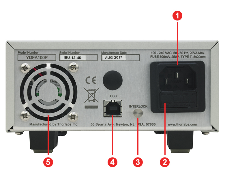
Figure 6.2 Back Panel

Click to Enlarge
Figure 6.1 Front Panel
| Back Panel | |
|---|---|
| Callout | Description |
| 1 | AC Power Cord Connector |
| 2 | Fuse Tray |
| 3 | Remote Interlock |
| 4 | USB Type-B Port for Remote Interface |
| 5 | Cooling Fan (Do Not Block) |
| Front Panel | |
|---|---|
| Callout | Description |
| 1 | Control Knob to Adjust Pump Laser Current and Temperature |
| 2 | Display to Show Pump Laser Temperature and Drive Current |
| 3 | Optical Input for PM FC/APC Fiber Connector |
| 4 | Optical Output for PM FC/APC Fiber Connector |
| 5 | Amplifier Emission Indicator |
| 6 | Amplifier Enable Switch |
| 7 | Key Switch for Power |
YDFA300P Amplifier Front and Back Panels
Click to Enlarge
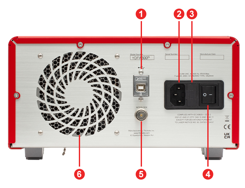
Figure 6.4 Back Panel

Click to Enlarge
Figure 6.3 Front Panel
| Back Panel | |
|---|---|
| Callout | Description |
| 1 | USB Type-B Port for Diagnostics and Remote Interface |
| 2 | AC Power Cord Connector |
| 3 | Fuse Tray |
| 4 | AC Power Switch |
| 5 | Remote Interlock Input (BNC) |
| 6 | Cooling Fan (Do Not Block) |
| Front Panel | |
|---|---|
| Callout | Description |
| 1 | Key Switch for Power |
| 2 | Display to Show Pump Level, Temperature Status, and Emission Status |
| 3 | Control Knob to Adjust Pump Laser Current |
| 4 | Amplifier Enable Switch and Emission Indicator |
| 5 | Optical Output for Single Mode FC/APC Fiber Connector |
| 6 | Optical Input for Single Mode FC/APC Fiber Connector |
The YDFA100S and YDFA100P amplifiers contain the following components:
- Ytterbium-Doped Fiber Amplifier in Benchtop Package
- Amplifier Enable Key (Qty. 2)
- Interlock-Shorting Pin
- Region-Specific Power Cord
- Type-A to Type-B USB Cable (Item # USB-A-79)
- FBC250 Connector and Bulkhead Cleaner
The YDFA300P amplifier contains the following components:
- Ytterbium-Doped Fiber Amplifier in Benchtop Package
- Amplifier Enable Key (Qty. 2)
- Interlock-Shorting BNC Connector
- Region-Specific Power Cord (6' long)
- Type-A to Type-B USB Cable (Item # USB-A-79)
- FBC250 Connector and Bulkhead Cleaner
- 1 m FC/APC-Terminated Patch Cable for Connection to the Output Port (Item # P3-980PM-FC-1)
- Sacrificial Fiber Interface (for Connection to the Output Port)*
- Test Data Sheet
*If the sacrifical interface becomes damaged, replacements are available by contacting Tech Support.
| Posted Comments: | |
Luis Ledezma
(posted 2024-04-17 08:51:07.877) Over the years we bought several YDFA100p, and have damaged the pump many, many times.
For instance, it is very easy to cause damage to the pump due to back-reflections. It would be extremely convenient if it was possible to pull both, input and output connectors, so the fiber tips can be properly inspected and cleaned. Right now this simple tasks requires opening the box and voiding Thorlabs warranty. The issues is similar if one wants to splice the YDFA to an external isolator.
Another improvement could be to add a WDM at the pump, so reflected power at the signal wavelength doesn't reach the pump. cdolbashian
(posted 2024-04-26 02:35:27.0) Thank you for reaching out to us with this concerning feedback. I have contacted you directly to discuss some usage tips in order to prolong the lifetime of these units, as well as to inquire about your specific usage conditions. user
(posted 2021-05-27 17:04:52.043) Is there a rule of thumb for the maximum advisable pulse energy for longer input pulses (with nanosecond durations, for the sake of argument) operating at very low (single-shot to sub-kHz) repetition rates if you still keep the peak power below 500W? YLohia
(posted 2021-07-21 03:48:54.0) Thank you for contacting Thorlabs. Unfortunately, we do not have test data in this pulse regime and, therefore, we can only comment based on component specifications and general information on damage threshold of optical fibers: (a) fiber facet at the amplifier output is subject to damage threshold guidelines given on the website in the damage threshold tab here: https://www.thorlabs.com/newgrouppage9.cfm?objectgroup_id=949 (b) fiber isolator used inside the amplifier is specified to have a 500 W max peak power handling for nanosecond pulse widths. A factor to consider is that fiber amplifiers behave very differently in sub-kHz pulse rep rate regime than they do in few kHz-MHz regime. Please also note that the gain saturation dynamics of a YDFA occurs in msec time scale, hence, in a sub-kHz repletion rate regime, the amplifier gain saturation recovers in between pulses. This should be considered as it can have temporal impact on the pulse. There will be distortion to the pulses as a result of this effect, which is not specific to the YDFA100 device but rather fundamental to the fiber amplifiers. user
(posted 2021-05-03 16:58:57.643) Hi, can the YDFA100P work with a -25 dBm input? YLohia
(posted 2021-05-10 10:16:02.0) Hello, thank you for contacting Thorlabs. The YDFA100P will work at -25dBm input. You should expect ~23dB gain with 0 dBm output. A portion of this will be ASE (around ~2 dBm), which may need to be filtered out depending on the application requirements. SEUNGHO LEE
(posted 2021-05-04 11:22:05.02) I have question about the insertion max power. Can this device handle mid power laser about 200 mW ? So that can make 200mW to 300mW. YLohia
(posted 2021-05-04 11:17:00.0) The absolute max input power is rated at 10 dBm (10 mW) and the absolute max output power is 23 dBm (199.5 mW) so, unfortunately, this device cannot handle a 200 mW input and 300 mW output. user
(posted 2019-12-09 00:20:38.833) May I know whether YDFA100P work with signal at low repetition rates and ns pulse widths (eg., pulse width 3-5 ns; repetition rate: 10-100kHz. What is the minimum repetition rate on can operate for ns pulse amplification? What is the maximum input peak power for the amplifier at which gain of 22dB is available? YLohia
(posted 2019-12-12 03:51:57.0) Hello, thank you for contacting Thorlabs. Unfortunately, we do not have experimental data in this pulse regime. Any information given below is not guaranteed since we do not have the appropriate source to test. General guidelines related to this specific pulse condition are the following:
1. Upper-state lifetime of Yb is in ms range according to literature. Exact lifetime of this particular Yb-doped fiber is unknown as this depends on concentration and other factors in the host glass. Assuming the lifetime is around a ms, both 10 kHz and 100 kHz should be fast enough such that the amplifier gain saturation does not recover in between pulses. Hence, the amplifier would respond to the average power at the input.
2. With the argument in 1, the gain of the amplifier would saturate based on the input average power. If input average power is around -20 dBm (calculated based on pulse width, rep rate and peak power), the system should provide the 22 dB gain at 1050 nm.
3. One key parameter to watch for here is the output peak power. Our components are rated to max peak power of 500 W. A higher peak power can cause damage to the components, although this is somewhat dependent on pulse energy as well.
4. In this pulse regime, one should also be very careful with ASE noise coming out of the amplifier. The system produces 20-30 mW of ASE power with zero input. That means, when seeded with low input average powers (below ~ -15 dBm), a good portion of the output power will consist of ASE. The easiest way to minimize the impact of that is to use a narrow-band filter at the signal wavelength to remove the out-of-band ASE. For example, a 0.1 nm filter would easily pass the ns pulses through, but will eliminate > 99% of the ASE. Vasili Savitski
(posted 2019-11-25 13:59:26.367) Dear Sir/Madam,
I have a question about your Yb-doped amplifier (YDFA100P or -S). Would it be possible to use it for amplification of pulsed emission at 1064 nm with the pulse duration of 5 ns, repetition rate of 4 MHz and average power of 3mW? The emission linewidth is 0.15 nm. What sort of output powers may I expect in the output, if the amplifier is suitable for this task?
Thank you.
Vasili. llamb
(posted 2019-12-02 09:54:27.0) Hello Vasili, thank you for your feedback. Our Yb-doped amplifiers will indeed work well for the input you have described. The output average power will be around 20 dBm (100 mW) with this input. kkmion
(posted 2018-08-27 22:34:52.53) Can the output power up to 30dBm? YLohia
(posted 2018-08-29 10:57:44.0) Hello, the absolute maximum output power is 23 dBm so, unfortunately, it cannot output 30 dBm. |

 Zoom
ZoomClick to Enlarge
Figure G1.1 This plot gives the wavelength-dependent output power as a function of input power for our YDFA100x units. Data was taken using a CW input at 1050 nm, the maximum pump current of 1000 mA, and the factory pump temperature setting of 25 °C. A complete set of performance graphs is available on the Graphs tab.
- Ideal for Use as a Preamplifier for Input Signal Powers ≥ -20 dBm
- <0.2 ps/nm Dispersion Within Amplifier to Minimize Pulse Broadening
- Provides Minimal Nonlinearity for Ultrafast Applications
- Constant Current Mode Operation
- Suitable for CW and Pulsed Signals
Thorlabs' YDFA100x core-pumped ytterbium-doped fiber amplifiers (YDFAs) offer 20 dB typical output power (>19 dBm minimum) at 3 dBm input power, with a low noise figure of <8 dB. The YDFA100S amplifier is a single mode YDFA with minimal sensitivity to the input light polarization, while the YFDA100P amplifier is a polarization-maintaining YDFA that only amplifies light polarized along the slow axis of the fiber. Each YDFA100x device includes built-in input and output isolators. In order to support applications involving femtosecond pulses, they are engineered to impart minimal dispersion. The fs Pulse Amplification tab contains more details on femtosecond operation.
The pump current of the YDFA100x amplifier is adjustable through the instrument's front panel, allowing the user to vary the gain and output power of the amplifier (see the Front & Back Panels tab). In addition, remote control of the pump current is supported by sending serial commands via a USB Type-B connector; drivers are available on the Software tab. For added safety, the user may connect an interlock circuit to the 2.5 mm mono jack on the rear panel.
Each EDFA100x amplifier uses a universal power supply allowing operation over 100 - 240 VAC, 50 - 60 Hz without the need to select the line voltage. A region-specific power cord is included. For a full list of items shipped with each YDFA100x device, please see the Shipping List tab.

 Zoom
ZoomClick to Enlarge
Figure G2.1 This plot gives the wavelength-dependent output power as a function of input power for our YDFA300P units. Data was taken with the pump level set to 100% using a CW input at 1050 nm. A complete set of performance graphs is available on the Graphs tab.
- Ideal Uses:
- Preamplifier for Signal Powers ≥ -5 dBm (Minimum Input Power)
- Booster Between a Preamplifier and a Power-Amplifier Stage
- Constant Current, Power, and Gain Operation Modes
- Suitable for CW and Pulsed Signals
Thorlabs' YDFA300P core-pumped ytterbium-doped fiber amplifier (YDFA) offers >25 dBm output power at 3 dBm input power, with a low noise figure of <6 dB. The YFDA300P amplifier is a polarization-maintaining YDFA that only amplifies input light polarized along the slow axis of the fiber. Each YDFA300P instrument includes built-in input and output isolators to protect the input laser source from any amplified spontaneous emission or back reflections, as well as to prevent the pump light from exiting the amplifier.
Each unit includes a 1 m FC/APC patch cable, and this cable should be connected to the output at all times to protect the output receptacle from the optical damage caused by repeated connections. A sacrificial optical interface compatible with FC/APC connectors is also supplied with each unit, which can be plugged into the output port of the amplifier, and all fiber cable connections can be made to this interface. Note that this option will introduce approximately 0.7 dB of extra insertion loss, but it offers the advantage of preventing direct contact between a fiber cable and the internal connector surface. For a full list of items shipped with each YDFA300P device, please see the Shipping List tab.
Operation Modes
The YDFA300P device can be operated in three modes, including automatic current control (ACC), automatic power control (APC), and automatic gain control (AGC). ACC mode drives the pump current in the YDFA at a fixed level and is accessible through the instrument's front panel. The user can vary the gain and output power level of the instrument by adjusting the pump current level. These fiber amplifiers can also be operated in APC or AGC mode, which maintain fixed output power or fixed gain, respectively. Note that these two operation modes are only accessible through a command-line interface; the YDFA300P device can be connected to a PC via the USB
The command line interface can also be used to enable or disable the amplifier, set the current level in the ACC mode, or read status indicators. The indicators available through the USB interface include temperature error, interlock status, and emission status. For more details on these features, please refer to the instrument manual.
Each YDFA uses a universal power supply allowing operation over 100 - 240 VAC,