 Products Home / Fiber Fusion Splicers and Processing Equipment / Fusion Splicers / Vytran® CO₂ Laser End-Cap Splicer
Vytran® CO₂ Laser End-Cap Splicer

- Splice End Caps Up to Ø9.5 mm
- For Use with or without Lead-In
- Automated Fiber Alignment
- CO2 Laser Provides Clean, Uniform
Heating
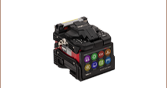
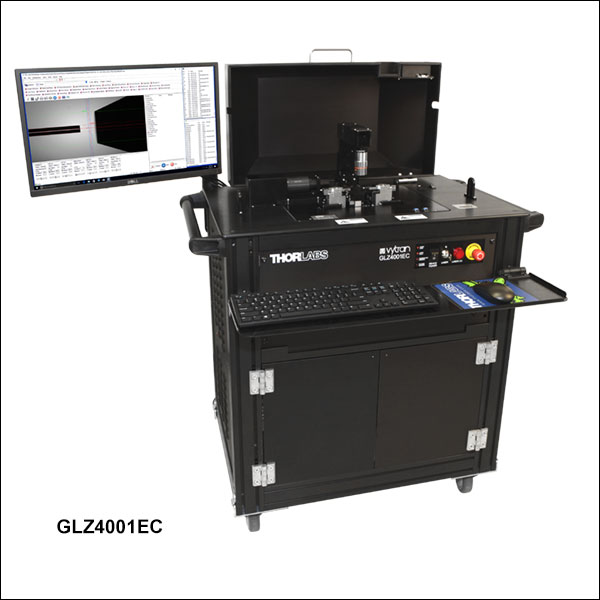
GLZ4001EC
Application Idea
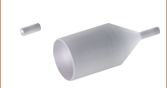
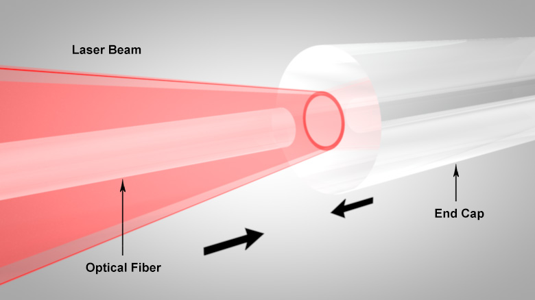
Ø400 µm Core Fiber Spliced onto a Ø8 mm Tapered End Cap with a Ø1 mm Lead-In
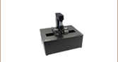
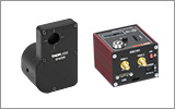
ECH5C
Ø5.0 mm End-Cap Holder with Flexure Clamp


Please Wait
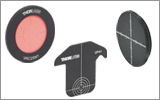
Click to Enlarge
Figure 1.1 Image of a Ø8 mm end cap with lead-in prepared for splicing in the GLZ4001EC.
Click to Enlarge
Figure 1.2 When splicing, the laser forms an annular beam shape that uniformly heats the fiber ends and then the two fibers are carefully pushed together.
Features
- Splice End Caps Up to Ø5 mm Directly to Fiber
- Splice End Caps Up to Ø9.50 mm with Lead-In
- Integrated 40 W, Air-Cooled CO2 Laser with Adjustable Annular Beam Output; No Consumables Needed
- Create Low-Loss (~0.02 dB) Splices in Standard Glass Fibers (See Specs Tab for Details)
- Automated Fiber Alignment
- Side-View Imaging and Splice Loss Determination using True Core Imaging® Technology
- Software with Process Development GUI and Splice Process Library
- Customizable with Fiber Holder Inserts and Additional Options
The GLZ4001EC is an advanced splicer that is designed for splicing single mode, multimode, and specialty fiber directly to large-diameter end caps. Direct splices to end caps up to Ø5.0 mm are enabled by the use of a high-power CO2 laser to precisely and uniformly heat the fiber and end cap during the fusion process. With a tapered lead-in, end caps up to Ø9.50 mm can be spliced (see Figure 1.2 for an example of a tapered end cap).
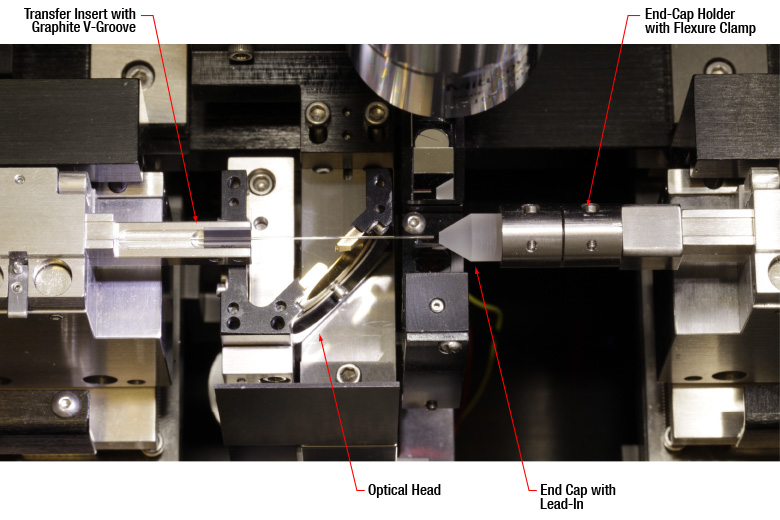
Unlike our other splicers, the furnace tower on the GLZ4001EC uses a 40 W (CW) CO2 laser as the primary heat source. In contrast to filament-based heat sources, the laser does not require purge gas or consumable filaments, which greatly reduces the maintenance needed. High-performance axicon lenses are used to shape the laser beam into an annular (i.e., doughnut) beam shape. There are two options for optical heads that are used to focus the laser beam; the splice head is optimized for splicing standard fibers together, while the end-cap head is designed for heating and fusing large end caps onto the ends of optical fibers. One optical head is included with the system based on your requirements. With the optics located in the rear of the system, the front of the GLZ4001EC allows the user unhindered access to fiber holding blocks and end caps.
The splicer workstation, computer with process development and operation software, and power supply are integrated into a rolling cart for easy movement in the workspace. Each system includes installation, commissioning, and training provided by one of our application engineers.
True Core Imaging
The GLZ4001EC employs our True Core Imaging technology to provide high-resolution images for fiber measurement and alignment. A digital CCD camera and mirror tower are integrated into the fiber processing workstation to allow for clear side-view images of the fiber cladding and core. This imaging feature allows for automated measurement of fiber properties, provides feedback for the automated alignment system, and enables calculation of an accurate splice loss for splices with similar or dissimilar fiber types.
Options and Accessories
A complete end-cap splicer requires the purchase of the GLZ4001EC Workstation, two top inserts (sold separately below), and two bottom inserts (sold separately below) or one bottom holder and an end-cap holder. End-cap holders for holding end caps from Ø0.95 mm to Ø9.50 mm during the fusion process are sold separately below. The GPXM45 bottom insert with 45° mirror is an optional accessory for providing an additional method for inspection of fiber end faces and alignment of fiber components. An ultrasonic cleaner for preparing fibers for splicing can be purchased separately below. Table 1.3 provides links to complimentary systems that can be used with the GLZ4001EC. Many of them, such as the large-diameter fiber cleaver and fiber preparation system are compatible with the same transfer inserts and can be used to transport fiber from system to system.
| Table 1.3 Compatible Vytran Fiber Processing Systems | |||||||
|---|---|---|---|---|---|---|---|
| Fiber Preparation Station (Strip and Clean) |
Large-Diameter Fiber Cleavers | Large-Diameter Fiber Splicer | CO2 Laser End-Cap Splicer | CO2 Laser Glass Processing System (Splice and Taper) |
Automated Glass Processing Systems with Cleaver (Cleave, Splice, and Taper) |
Automated Glass Processing Systems (Splice and Taper) |
Recoaters and Proof Testers |
| Item # | GLZ4001EC |
|---|---|
| Heat Source Specifications | |
| Laser Wavelength | 10.55 µm (Minimum) 10.63 µm (Maximum) |
| Laser Output Power | 40 Wa |
| Laser Safety Features | Metal Cover with Interlock Class 1 Enclosure Automatic Laser Power Cutoff Double Redundancy Safety Measures |
| Laser Beam Control | Closed-Loop Feedback System |
| Splicing Specifications | |
| Fiber Types | Single Mode, Multimode, Photonic Crystal, Large Mode Area, Non-Circularb |
| Accepted Fiber Diameters | Splice: 250 µm Coating - 2 mm End Caps: 250 µm Coating - 5 mmc |
| Splice Loss | 0.02 dB (Typical)d |
| Splice Loss Estimation | True Core Imaging® Technology |
| Splice Strength | >250 kpsi (Typical)e |
| Fiber Inspection Features | |
| Fiber Side Viewing | True Core Imaging Technology |
| Core / Cladding / Fiber Diameter | Automated Measurement |
| Cleave Angle | Automated Measurement |
| Fiber and End Face Alignment | |
| Furnace Z-Axis Travel | 15 mm (Max) |
| Fiber Holding Block (FHB) Z-Axis Movement | 10 mm (Max) |
| FHB Z-Axis Movement Resolution | 0.25 µm via Stepper Motor |
| XY Axis Fiber Positioning Resolution | 0.2 µm via Stepper Motor |
| Computer and Software | |
| Workstation Computer | Included |
| Splice Files | Built-In Library for Common Fibers and Processes |
| Physical | |
| Size | 36.4" x 31.3" x 44.2" (924 mm x 795 mm x 1122 mm) |
| Weight | 300 lbs (136 kg) |
| Power Input | 100 - 240 VAC, 47 - 63 Hz, 14.7 A |
| Environmental | |
| Operating Temperature | 15 to 40 °C |
| Altitude Range | 0 to 2000 m Above Sea Level |
| Operating Humidity | 0% to 75% Relative Humidity (Non-Condensing) |
| Storage Temperature | -20 to 60 °C |
| Storage Humidity | 0% to 90% Relative Humidity (Non-Condensing) |
Fiber Holder Inserts Selection Guide (Top Inserts and Standard or Transfer Bottom Inserts)
Fiber Holder Inserts, which are designed to hold various sized fibers within the glass processors, must be purchased separately. Standard and transfer bottom inserts have V-grooves to hold the fiber, while the top inserts each feature a recessed, flat surface that clamps the fiber against the V-groove in the bottom insert. Each top and bottom insert is sold individually, as the fiber outer diameter clamped by the left and right holding blocks may not be the same. At least two top inserts and two bottom inserts are required to operate the glass processor. For multi-fiber inserts, which are used to make fused couplers or combiners, the recommended top inserts are listed in the multi-fiber insert table.
Table 3.3 indicates the maximum and minimum outer diameters that can be accommodated by different combinations of top and bottom inserts. It also indicates how far offset the fiber will be for recommended combinations of top and bottom inserts. Note that this outer diameter may be the fiber cladding, jacket, or buffer. If one side of the fiber is being discarded, it is preferable to clamp onto the cladding of this section except in special cases (such as non-circular fiber) where the coating or buffer may be preferable. Sections of fiber that are not being discarded should always be clamped on the coating or buffer in order to avoid damaging the glass. This may require different sets of fiber holder inserts to be used in the left and right holding blocks. In this case, it is important to minimize the difference in the offsets introduced by the left and right sets of inserts when attempting to produce high-quality splices.
Figure 3.1 Each V-groove can accommodate a range of fiber sizes.
| Table 3.2 Legend | ||
|---|---|---|
|
|
Best Fit | |
|
|
Second Best Fit: Try these options if the best fit does not incorporate your fiber sizes. | |
|
|
Third Best Fit: Try these options if the other two categories do not incorporate your fiber sizes. | |
Fiber Insert Selection Chart
- First, select the bottom insert that matches your fiber size most closely.
Example: For a Ø800 µm fiber, the VHF750 insert is the closest match, since it is only 50 µm smaller. - In Table 3.3, look to the right of your chosen bottom insert. Select a compatible top insert based on the accepted diameter size range shown in each cell.
Example: For the Ø800 µm example fiber from step 1, the green cell is in the 750 µm groove column for the VHA05 top insert, which has two grooves. The numbers listed in the green cell indicate that this combination of inserts is good for fibers from 728 to 963 µm in diameter. Our Ø800 µm fiber is within this range, so this is a good choice. There are several other options that will accommodate a Ø800 µm fiber as well, but the green shading in the chart indicates that the 750 µm groove in the VHA05 provides the best fit. - The second line of numbers in each cell shows the range of offsets that can be expected for any given combination of top and bottom inserts. When selecting inserts for the right and left fiber holding blocks, try to minimize the offsets between the pairs of inserts on each side.
Example: If we choose a VHF750 bottom insert and the Ø750 µm groove in the VHA05 top insert, we can use fiber as small as 728 µm, in which case the center of the fiber would sit 23 µm below the surface of the bottom insert. We could also clamp a fiber as large as 963 µm, in which case the center of the fiber would sit 213 µm above the surface of the bottom insert. We could interpolate to find the offset experienced by our hypothetical 800 µm fiber, but it turns out that in a 60° V-groove, the offset is equal to the outer diameter difference. So in our example, that means that the center of our fiber is going to sit 50 µm above the bottom insert surface, since it is 50 µm larger than the fiber that the bottom insert was designed for (800 - 750 = 50). - Holding blocks designed for fibers less than Ø1000 µm have vacuum holes, designed to aid in aligning small fiber within the groove, while bottom inserts for fibers of Ø1000 µm or larger do not have these holes. The glass processors have a vacuum pump that provides a small holding force via these holes, keeping small fibers in place as the clamps are lowered. Inserts with vacuum holes are indicated by a superscript "d" in Table 3.3.
| Table 3.3 Insert Selection Chart | |||||||||||||
|---|---|---|---|---|---|---|---|---|---|---|---|---|---|
| Top Insert Item # | VHA00a VHB00b |
VHA00a | VHA05c VHB05b |
VHA10c | VHA15c | VHA20c | VHA25 | VHA30 | |||||
| Accepted Diameter (Nominal) | ≤320 µm | 400 µm | 500 µm | 750 µm | 1000 µm | 1250 µm | 1500 µm | 1750 µm | 2000 µm | 2250 µm | 2500 µm | 3000 µm | |
| Bottom Insert Item # |
Accepted Diameter (Nominal) |
Min / Max Accepted Diameter (µm) Min / Max Fiber Offset (µm) |
|||||||||||
| VHF160d,e | 160 µm | 112 / 208 -49 / 48 |
- | - | - | - | - | - | - | - | - | - | - |
| VHF250d,e |
250 µm | 177 / 320 -73 / 69 |
275 / 323 23 / 74 |
- | - | - | - | - | - | - | - | - | - |
| VHF400d,e |
400 µm | 279 / 519 -122 / 119 |
377 / 517 -23 / 117 |
410 / 519 -9 / 119 |
- | - | - | - | - | - | - | - | - |
| VHF500d,e |
500 µm | 346 / 592 -153 / 93 |
447 / 647 -53 / 147 |
476 / 711 -24 / 211 |
560 / 795 61 / 296 |
- | - | - | - | - | - | - | - |
| VHF750d,e |
750 µm | 516 / 759 -234 / 9 |
617 / 970 -132 / 221 |
643 / 878 -107 / 128 |
728 / 963 -23 / 213 |
812 / 1047 62 / 297 |
- | - | - | - | - | - | - |
| VHE10c | 1000 µm | - | - | 773 / 1008 -172 / 63 |
858 / 1093 -88 / 147 |
943 / 1178 -3 / 232 |
1036 / 1271 90 / 325 |
- | - | - | - | - | - |
| 1250 µm | - | - | - | 1034 / 1269 -176 / 59 |
1119 / 1354 -91 / 144 |
1212 / 1447 2 / 237 |
1288 / 1523 78 / 313 |
- | - | - | - | - | |
| VHE15c | 1500 µm | - | - | - | - | 1280 / 1515 -172 / 63 |
1373 / 1608 -79 / 156 |
1449 / 1684 -2 / 233 |
1534 / 1769 82 / 314 |
- | - | - | - |
| 1750 µm | - | - | - | - | - | 1534 / 1770 -159 / 76 |
1611 / 1846 -83 / 152 |
1695 / 1930 2 / 237 |
1772 / 2007 78 / 313 |
- | - | - | |
| VHE20c | 2000 µm | - | - | - | - | - | - | 1787 / 2022 -171 / 64 |
1871 / 2106 -86 / 149 |
1947 / 2183 -10 / 225 |
2032 / 2267 74 / 309 |
- | - |
| 2250 µm | - | - | - | - | - | - | - | 2033 / 2268 -167 / 68 |
2109 / 2344 -91 / 144 |
2193 / 2429 -6 / 229 |
2278 / 2513 78 / 313 |
- | |
| VHE25 | 2500 µm | - | - | - | - | - | - | - | - | 2270 / 2505 -172 / 64 |
2355 / 2590 -87 / 148 |
2439 / 2675 -2 / 233 |
2609 / 2844 167 / 402 |
| VHE30 | 3000 µm | - | - | - | - | - | - | - | - | - | 2692 / 2944 -256 / -4 |
2777 / 3029 -171 / 81 |
2946 / 3198 -2 / 250 |
Setup
To assist new or returning GLZ4001EC CO2 laser glass processor users with operating their glass processors, we have created a series of tutorials aimed at teaching the basic skills needed to run this machine including hardware installation, insert assembly, and CO2 safety. To read the text in the videos, we strongly recommend viewing them at full screen, 1080p resolution. If you require assistance performing other operations using your GPX glass processor, please contact Tech Support.
Laser Safety and Classification
Safe practices and proper usage of safety equipment should be taken into consideration when operating lasers. The eye is susceptible to injury, even from very low levels of laser light. Thorlabs offers a range of laser safety accessories that can be used to reduce the risk of accidents or injuries. Laser emission in the visible and near infrared spectral ranges has the greatest potential for retinal injury, as the cornea and lens are transparent to those wavelengths, and the lens can focus the laser energy onto the retina.
 |
 |
 |
 |
 |
 |
 |
 |
 |
Safe Practices and Light Safety Accessories
- Laser safety eyewear must be worn whenever working with Class 3 or 4 lasers.
- Regardless of laser class, Thorlabs recommends the use of laser safety eyewear whenever working with laser beams with non-negligible powers, since metallic tools such as screwdrivers can accidentally redirect a beam.
- Laser goggles designed for specific wavelengths should be clearly available near laser setups to protect the wearer from unintentional laser reflections.
- Goggles are marked with the wavelength range over which protection is afforded and the minimum optical density within that range.
- Laser Safety Curtains and Laser Safety Fabric shield other parts of the lab from high energy lasers.
- Blackout Materials can prevent direct or reflected light from leaving the experimental setup area.
- Thorlabs' Enclosure Systems can be used to contain optical setups to isolate or minimize laser hazards.
- A fiber-pigtailed laser should always be turned off before connecting it to or disconnecting it from another fiber, especially when the laser is at power levels above 10 mW.
- All beams should be terminated at the edge of the table, and laboratory doors should be closed whenever a laser is in use.
- Do not place laser beams at eye level.
- Carry out experiments on an optical table such that all laser beams travel horizontally.
- Remove unnecessary reflective items such as reflective jewelry (e.g., rings, watches, etc.) while working near the beam path.
- Be aware that lenses and other optical devices may reflect a portion of the incident beam from the front or rear surface.
- Operate a laser at the minimum power necessary for any operation.
- If possible, reduce the output power of a laser during alignment procedures.
- Use beam shutters and filters to reduce the beam power.
- Post appropriate warning signs or labels near laser setups or rooms.
- Use a laser sign with a lightbox if operating Class 3R or 4 lasers (i.e., lasers requiring the use of a safety interlock).
- Do not use Laser Viewing Cards in place of a proper Beam Trap.
Laser Classification
Lasers are categorized into different classes according to their ability to cause eye and other damage. The International Electrotechnical Commission (IEC) is a global organization that prepares and publishes international standards for all electrical, electronic, and related technologies. The IEC document 60825-1 outlines the safety of laser products. A description of each class of laser is given below:
| Class | Description | Warning Label |
|---|---|---|
| 1 | This class of laser is safe under all conditions of normal use, including use with optical instruments for intrabeam viewing. Lasers in this class do not emit radiation at levels that may cause injury during normal operation, and therefore the maximum permissible exposure (MPE) cannot be exceeded. Class 1 lasers can also include enclosed, high-power lasers where exposure to the radiation is not possible without opening or shutting down the laser. |  |
| 1M | Class 1M lasers are safe except when used in conjunction with optical components such as telescopes and microscopes. Lasers belonging to this class emit large-diameter or divergent beams, and the MPE cannot normally be exceeded unless focusing or imaging optics are used to narrow the beam. However, if the beam is refocused, the hazard may be increased and the class may be changed accordingly. |  |
| 2 | Class 2 lasers, which are limited to 1 mW of visible continuous-wave radiation, are safe because the blink reflex will limit the exposure in the eye to 0.25 seconds. This category only applies to visible radiation (400 - 700 nm). |  |
| 2M | Because of the blink reflex, this class of laser is classified as safe as long as the beam is not viewed through optical instruments. This laser class also applies to larger-diameter or diverging laser beams. |  |
| 3R | Class 3R lasers produce visible and invisible light that is hazardous under direct and specular-reflection viewing conditions. Eye injuries may occur if you directly view the beam, especially when using optical instruments. Lasers in this class are considered safe as long as they are handled with restricted beam viewing. The MPE can be exceeded with this class of laser; however, this presents a low risk level to injury. Visible, continuous-wave lasers in this class are limited to 5 mW of output power. |  |
| 3B | Class 3B lasers are hazardous to the eye if exposed directly. Diffuse reflections are usually not harmful, but may be when using higher-power Class 3B lasers. Safe handling of devices in this class includes wearing protective eyewear where direct viewing of the laser beam may occur. Lasers of this class must be equipped with a key switch and a safety interlock; moreover, laser safety signs should be used, such that the laser cannot be used without the safety light turning on. Laser products with power output near the upper range of Class 3B may also cause skin burns. |  |
| 4 | This class of laser may cause damage to the skin, and also to the eye, even from the viewing of diffuse reflections. These hazards may also apply to indirect or non-specular reflections of the beam, even from apparently matte surfaces. Great care must be taken when handling these lasers. They also represent a fire risk, because they may ignite combustible material. Class 4 lasers must be equipped with a key switch and a safety interlock. |  |
| All class 2 lasers (and higher) must display, in addition to the corresponding sign above, this triangular warning sign. |  |
|
 Product DemonstrationsThorlabs has demonstration facilities for the Vytran® fiber glass processing systems offered on this page within our Morganville, New Jersey; Shanghai, China; and Exeter, Devonshire offices. We invite you to schedule a visit to see these products in operation and to discuss the various options with a fiber processing specialist. Please schedule a demonstration at one of our locations below by contacting technical support. We welcome the opportunity for personal interaction during your visit! Thorlabs Vytran Europe
|
.jpg)
| Posted Comments: | |
| No Comments Posted |

 Zoom
ZoomComponents Included
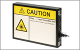
- CO2 Laser End-Cap Splicer in Rolling Cart
- Air-Cooled 40 W CO2 Laser
- Optical Splice Head and End-Cap Head
- Integrated Computer with Monitor, Keyboard, and Mouse
- Software Interface with Example Splice Files
- Vacuum Pump for Bottom Fiber Inserts
- Gooseneck Light for Illumination
- Tool Kit with Hex Keys
Must be Purchased Separately
- Fiber Holder Top Inserts (Two Required)
- Fiber Holder Bottom Inserts (Two Required for Single Fiber Processing)
- Transfer Clamp and Graphite V-Grooved Inserts (Required to Use Transfer Inserts)
- End-Cap Holders (Required For Holding Ø0.95 mm to Ø9.50 mm End Caps)
Optional Accessories
- Includes End-Cap Splicer Workstation and Computer with Control Software
- CO2 Laser Provides Uniform Heating Necessary for Large-Diameter Splicing
- Automatic Fiber Alignment
- Ideal for Splicing Single Mode, Multimode, and Specialty Fibers
- No Consumables Required
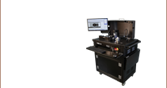
The GLZ4001EC CO2 Laser End-Cap Splicer Workstation integrates the furnace tower, fiber holding blocks, computer with operation and process development software, and other operational equipment into an easy-to-use rolling cart that can be positioned anywhere in the lab.
This workstation features automatic fiber alignment and is specially designed for fusing large end caps to single mode, multimode, and other specialty fiber using the True Core Imaging® technology. Precision fiber handlers can translate and position a fiber in XY with a resolution of 0.2 µm and translate along the fiber axis (Z-axis) up to 10 mm with a resolution of 0.25 µm. This allows the furnace to precisely and uniformly heat the fiber or end cap to ensure a high-quality splice directly to end caps up to Ø5 mm. With a tapered lead-in, end caps up to Ø9.50 mm can be spliced.
The workstation includes the fiber holders, optical heads, furnace tower, CCD camera for imaging, PC and monitor pre-installed with the control software, and mirror tower for side-view imaging.
Top and bottom inserts for the fiber holders, both of which are required to operate the splicer workstation, can be purchased separately below. Our end-cap holders (sold separately below) can hold larger end caps from Ø0.95 mm to Ø9.50 mm using vacuum suction, a flexure clamp, or a magnetic lid.
Installation, commissioning, and training by one of our application engineers is included with the purchase of a system.

 Zoom
Zoom| Table G2.1 Top Inserts | ||
|---|---|---|
| Item # | Side 1 Accepted Diameter (Min/Max) |
Side 2 Accepted Diameter (Min/Max) |
| VHA00 | 57 µm / 759 µma | 275 µm / 970 µm |
| VHA05 | 410 µm / 1008 µm | 560 µm / 1269 µm |
| VHA10 | 812 µm / 1515 µm | 1036 µm / 1770 µm |
| VHA15 | 1288 µm / 2022 µm | 1534 µm / 2268 µm |
| VHA20 | 1772 µm / 2505 µm | 2032 µm / 2944 µm |
| VHA25 | 2278 µm / 3029 µm | N/A |
| VHA30 | 2609 µm / 3198 µm | N/A |
- Top Inserts for Fiber Holding Blocks
- Accepts Fiber Outer Diameter (Cladding/Coating) from 57 µm to 3.198 mm (See the Fiber Holder Insert Tab for Information on Choosing Inserts)
- Single-Sided and Dual-Sided Inserts Available (See Table G2.1 for Details)
- Also Compatible with Automate Glass Processors, LDC401 Series Fiber Cleavers, FPS301 Stripping and Cleaning Station, and LFS4100 Splicing System
Fiber Holder Inserts, which consist of one top insert and either a bottom or transfer insert, are placed in the fiber holding blocks of the optical glass processor to secure the fiber during splicing or tapering. The inserts clamp the cladding, buffer, or coating of the fiber and can accommodate outer diameters of up to 3.198 mm. Please refer to the Fiber Holder Insert tab for more information on pairing the top and bottom inserts sold here.
The VHA standard top inserts come in single-sided and dual-sided versions. These standard inserts can also be used in the Automated Glass Processors, CO2 Laser Glass Processor, LDC401 Series of Fiber Cleavers, FPS301 Stripping and Cleaning Station, and LFS4100 Splicing System.

 Zoom
Zoom| Standard and Transfer Inserts | ||||
|---|---|---|---|---|
| Item # | Type | Side 1 Accepted Diameter (Min/Max) |
Side 2 Accepted Diameter (Min/Max) |
Vacuum Holes |
| VHF160 | Transfer | 112 µm / 208 µm | N/A | Yes |
| VHF250 | Transfer | 177 µm / 320 µm | N/A | Yes |
| VHF400 | Transfer | 279 µm / 519 µm | N/A | Yes |
| VHF500 | Transfer | 346 µm / 795 µm | N/A | Yes |
| VHF750 | Transfer | 516 µm / 1047 µm | N/A | Yes |
| VHE10 | Standard | 773 µm / 1271 µm | 1034 µm / 1523 µm | No |
| VHE15 | Standard | 1280 µm / 1769 µm | 1534 µm / 2007 µm | No |
| VHE20 | Standard | 1787 µm / 2267 µm | 2033 µm / 2513 µm | No |
| VHE25 | Standard | 2270 µm / 2844 µm | N/A | No |
| VHE30 | Standard | 2692 µm / 3198 µm | N/A | No |
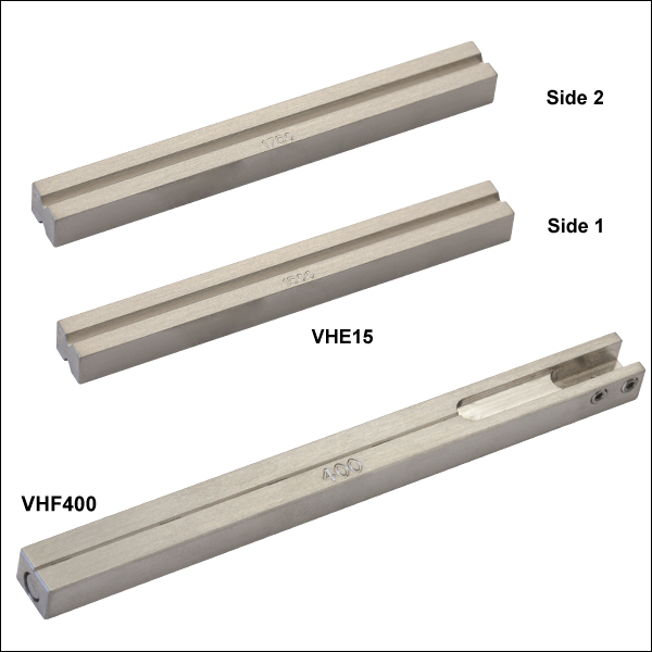
- Bottom Fiber Inserts with V-Groove(s) for Fiber Holding Blocks
- Compatible with Cladding/Coating Diameters from 112 µm to 3.198 mm (See the Fiber Holder Insert Tab for Information on Choosing Standard or Transfer Inserts)
- Transfer Inserts for Moving Fiber Between Vytran Systems
- Inserts with Vacuum Holes for Aligning Smaller Fibers (<Ø1047 µm) in V-Groove
Fiber Holder Inserts, which consist of one top insert and a bottom insert, are placed in the fiber holding blocks of the splicer workstation to secure the fiber during splicing or tapering. Bottom inserts are magnetically held within the fiber holding blocks of the splicer workstation and other compatible systems. The V-groove machined into the bottom inserts ensures the fiber is centered within the fiber holder; inserts with different V-groove sizes are available (see the Fiber Holder Insert tab for more information on pairing top and bottom standard or transfer inserts). Vacuum holes at the bottom of the transfer inserts are used for holding and aligning small fibers within the V-groove.
Two types of bottom inserts are compatible with the splicer workstation: transfer bottom inserts and standard bottom inserts. Transfer bottom inserts (indicated with Item #'s starting with VHF) allow for a single fiber to be transferred between the LDC401 Series of Fiber Cleavers, FPS301 Stripping and Cleaning Station, and the GLZ4001EC workstation with minimal loss of alignment. For example, a fiber can be placed in a transfer insert and cleaved using the LDC401 cleaver, then the entire transfer insert can be placed in the GLZ4001EC for splicing. This process works because the transfer inserts are precisely located within each Vytran system, and the VHT1 Transfer Clamp (sold directly below) prevents axial movement of the fiber during transport. Transfer inserts are equipped with vacuum holes that provide a small suction force to hold the fiber in place. All of these transfer inserts require the VHT1 Transfer Clamp (sold below); transfer inserts for fiber outer diameters ≤550 µm also require a Graphite V-Grooved Insert (sold below).
Standard Fiber Holder Bottom Inserts (indicated by Item #'s starting with VHE) can be used with fibers with large-diameter fibers. These inserts come in single-sided and dual-sided versions. The standard bottom inserts can also be used in the LDC401 Series of Fiber Cleavers, FPS301 Stripping and Cleaning Station, Automated Glass Processors and LFS4100 Splicing System. Unlike transfer inserts, alignment of the fibers will not be maintained when these inserts are transferred between systems.

 Zoom
Zoom| Table G4.1 Graphite V-Grooved Insertsa | ||
|---|---|---|
| Item # | Accepted Diameter (Min / Max) |
Groove Length |
| VHG125 | 80 µm / 125 µm | 0.313" |
| VHG125L | 80 µm / 125 µm | 0.594" |
| VHG200 | 150 µm / 200 µm | 0.313" |
| VHG250 | 200 µm / 250 µm | 0.313" |
| VHG250L | 200 µm / 250 µm | 0.594" |
| VHG300 | 250 µm / 300 µm | 0.313" |
| VHG350 | 300 µm / 350 µm | 0.313" |
| VHG400 | 350 µm / 400 µm | 0.313" |
| VHG450 | 400 µm / 450 µm | 0.313" |
| VHG500 | 450 µm / 500 µm | 0.313" |
| VHG500L | 450 µm / 500 µm | 0.594" |
| VHG550 | 500 µm / 550 µm | 0.313" |
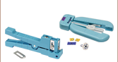
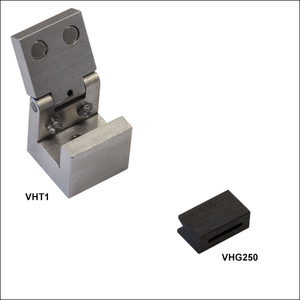
- Clamp and Graphite V-Grooved Inserts Used with Transfer Bottom Inserts to Move Fiber Between Vytran Systems
- One VHT1 Transfer Clamp Required with Transfer Bottom Inserts
- Graphite V-Groove for Supporting Smaller Fibers from Ø80 µm to Ø550 µm During Splicing
- Transfer Clamps are Also Compatible with LDC401 Series of Fiber Cleavers and FPS301 Stripping and Cleaning Station
These Transfer Clamps and V-Grooved Inserts are used with the VHF Transfer Bottom Inserts sold directly above to move a single fiber between various Vytran systems with minimal loss of alignment. For example, a fiber can be placed in a transfer insert and cleaved using the LDC401 Fiber Cleaver. Then, the entire transfer insert and fiber can be moved to the GLZ4001EC for splicing.
The VHT1 clamp secures transfer inserts with a magnetic lid that prevents axial movement of the fiber and can be used to hold the insert during transport without touching the fiber itself. For fibers with diameters ≤550 µm, a graphite V-grooved insert is available to support the fiber when splicing (please see Table G4.1 for more information). To provide extended support along the length of the fiber and reduce the amount of overhang during processing, we also offer 0.594" long V-grooved inserts (Item #'s VHG125L, VHG250L, and VHG500L). The graphite V-grooved inserts are secured by tightening two setscrews on the transfer insert. For information on how to assemble transfer inserts, see the Fiber Holder Inserts tab.

 Zoom
Zoom| Item # | Type | Accepted Length |
Accepted Diameter | End Cap Item # |
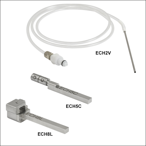
||
|---|---|---|---|---|---|---|
| Min. | Typ. | Max | ||||
| ECH1Va | Vacuum | 2.5 mm - 5.0 mm | 0.95 mm | 1.0 mm | 1.05 mm | FEC1 |
| ECH15Va | 1.45 mm | 1.5 mm | 1.55 mm | FEC15 | ||
| ECH2Va | 1.95 mm | 2.0 mm | 2.05 mm | FEC2 | ||
| ECH4C | Flexure Clamp | 2.5 mm - 10 mm | 3.8 mm | 4.0 mm | 4.08 mm | - |
| ECH5C | 4.8 mm | 5.0 mm | 5.08 mm | FEC5 | ||
| ECH8C | 7.8 mm | 8.0 mm | 8.08 mm | FEC8, FEC8S | ||
| ECH8L | Magnetic Lid | 2.5 mm - 10 mm | 7.6 mm | 8.0 mm | 9.50 mm | - |
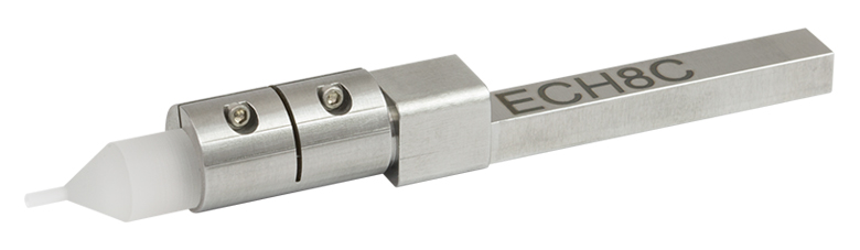
Click to Enlarge
Figure G5.1 An Ø8 mm end cap with a Ø1 mm lead-in is secured within the front clamp of the ECH8C.
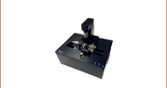
- For Holding Ø0.95 mm to Ø9.50 mm End Caps During Splicing
- Versions Equipped with Vacuum Suction, Clamp, or Magnetic Lid Available
- Compatible with Fiber Holding Blocks on Splicer Workstation
These holders secure and position end caps in the splicer workstation during the fusion process. Holders for end caps with outer diameters ranging from 0.95 mm to 9.50 mm are available.
Holder with Vacuum Suction
The ECH1V, ECH15V, and ECH2V End-Cap Holders use suction force to hold smaller Ø1.0 mm, Ø1.5 mm, and Ø2.0 mm end caps respectively within the steel tube holder. Suction is generated through the flexible tube via the connector plugged into the vacuum line labeled "VACUUM" at the rear of the workstation. To mount an end cap within the holder, pick up the end cap with tweezers and load it into the holder. The steel tube that holds the end cap features an internal step to prevent an end cap from being pulled into the steel tube entirely. Vacuum-style holders can be held between two fiber holding block inserts (Item #s VHA20 and VHE20) which can be purchased separately.
Holders with Flexure Clamp
The ECH4C, ECH5C, and ECH8C Holders use a flexure clamp that does not require a vacuum to operate and allows an end cap to be placed in close proximity to the furnace tower. These holders use a two-clamp system that enables adjustment of the flexure clamp position on the holder in order to accommodate different end-cap lengths from 2.5 mm to 10 mm. Tighten the screw using a torque wrench with a 0.050" (1.3 mm) hex to a torque of 0.04 N·m for best performance; do not overtighten the screw. These holders are directly compatible with the fiber holding block; they are used in place of a bottom insert in the fiber holding block.
Holders with Magnetic Lid
The ECH8L Holder features a hinged magnetic lid and a nylon-tipped setscrew to secure end caps up to Ø9.50 mm in place. To use, place the end cap on the v-groove and gently tighten the set screw using a 0.050" (1.3 mm) hex key or balldriver (not included). Overtightening the setscrew will cause the lid to lift and decrease the holding force on the end cap. This holders is directly compatible with the fiber holding block; it is used in place of a bottom insert in the fiber holding block.

 Zoom
Zoom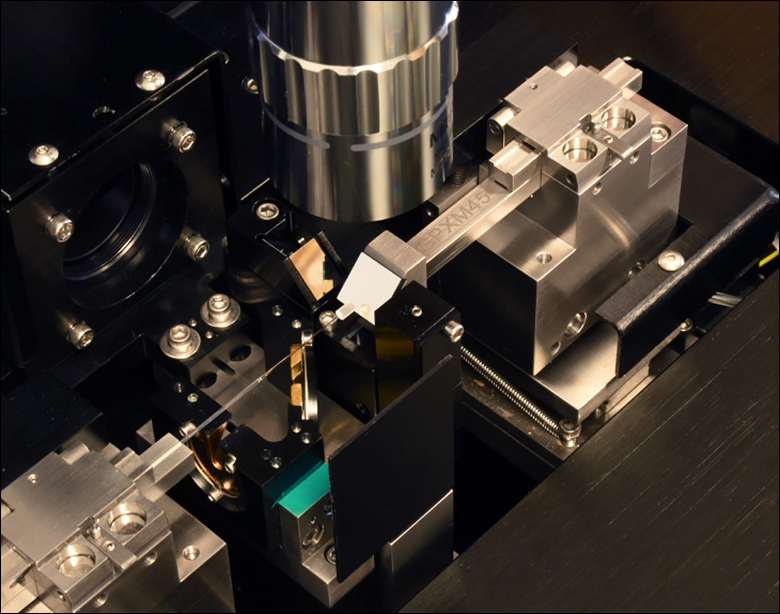
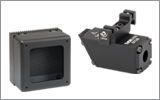
Click to Enlarge
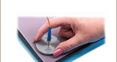
Figure G6.1 An example application shows the GPXM45 Insert being used in Top View to inspect the end face of an endcapped fiber on the GLZ4001EC CO2 Laser End-Cap Splicer Workstation.
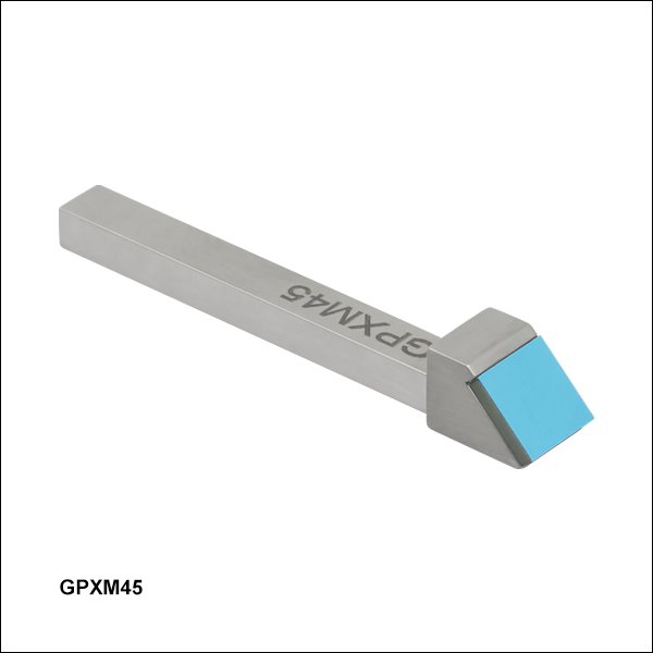
- For Inspection of Fiber End Faces and Alignment of Fiber Components
- 10 mm Square 45° Inspection Mirror
- Also Compatible with the LFS4100 Splicer, GPX3400 and GPX3600 Glass Fiber Processing Stations, GPX3800, GPX3850, and GPX3900 Glass Fiber Processing Stations, and the GPX4000LZ CO2 Laser Glass Processor Workstation.
The GPXM45 Insert with 45° Mirror provides an additional method for inspection of fiber end faces and alignment of fiber components. A fiber holding block on any of the compatible Vytran systems listed above secures the mirror insert in the same way as a fiber holder bottom insert. This mirror provides an additional view for the GLZ4001EC workstation, which does not have the ability to inspect the end face of the left side fiber before splicing or endcapping has occurred. Additionally, this mirror can be used outside the Vytran systems as a convenient inspection tool on an optical bench or a microscope.

 Zoom
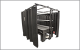
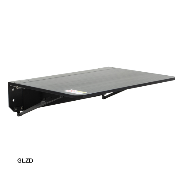
Zoom- Add-On Shelf for GLZ4001EC Laser Glass Processing System
- Maximum Load Capacity: 100 lbs (45 kg)
- Includes Mounting Hardware (T-Nuts, Bolts, and 3/16" Hex Key)
The GLZD Drop-Leaf Shelf is compatible with our GLZ4001EC and GPX4000LZ Processing Systems. The shelf includes mounting hardware and can attach to either side of the system enclosure. The supporting braces lock in place automatically when the shelf is raised. Each system enclosure can support one shelf on each side for a total of two.

Click to Enlarge
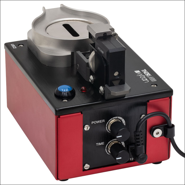
Figure 662A USC2 Ultrasonic Cleaner and USC2NVT Nest for Vytran Transfer Bottom Inserts
Click to Enlarge
Figure 662C The cleaning intensity and duration controls are located on the rear of the cleaner.
| USC2 Ultrasonic Cleaner Specifications | |
|---|---|
| Supported Fiber Diametera | 125 - 600 µm |
| Tank Capacity | 100 mL |
| Tank Dimensions | Ø1.7" x 2.8" Deep (Ø43 mm x 71 mm Deep) |
| Cleaning Duration (Max Setting) |
>1 Minute |
| Peak Output Frequency | 75.2 - 76.4 kHz |
| Transducer Power (Max) | 6 W |
| Operating Power | 36 W |
| Operating Current | 1.5 A |
| Input Voltageb | 100 - 240 VAC @ 47 - 63 Hz |
| Overall Dimensionsa |
6.95" x 4.78" x 4.13" (176.5 mm x 121.5 mm x 104.8 mm) |
| Mass | 1.28 kg (2.82 lbs) |
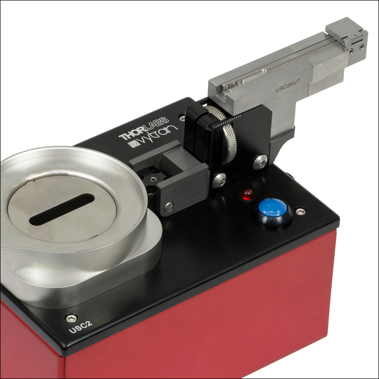
Click for Details Figure 662B The USC2NVT Nest adds support for Vytran transfer bottom inserts.
- Easy-to-Adjust Immersion Depth, Cleaning Duration, and Power Level
- Bare Fiber Nest with Magnetic Clamp Included
- Nest for Vytran Transfer Bottom Inserts Sold Separately (Item # USC2NVT)
- Compatible Solvents: Acetone or Isopropanol (Isopropyl Alcohol)
- Spout for Easy Fluid Disposal; Slotted Shield for Reduced Solvent Evaporation
Thorlabs' Vytran® USC2 Ultrasonic Fiber Cleaner is designed for volume processing of bare fiber. Adjustment knobs for cleaning intensity and cleaning duration allow the user to easily set repeatable cleaning parameters. The dunking jig offers adjustable immersion depth and is compatible with interchangeable fiber holder nests (each sold separately). A red LED indicates when the cleaning cycle is active. The 100 mL solvent tank is only suitable for use with acetone or isopropyl alcohol.
Tilting the dunking jig submerges the fiber in the tank and initiates the ultrasonic cleaning process. The ultrasonic agitation ceases after the chosen cleaning duration. The height of the fiber holder above the solvent tank can be changed over a 0.5" (12.7 mm) range using the knurled adjuster on the side of the dunking jig, visible in Figure 662B.
The knurled adjuster can also be reversed to disengage the bare fiber nest and switch it out for another fiber holder nest. Each cleaner is shipped with a bare fiber nest installed in the dunking jig. The USC2NVT Nest (sold separately) is designed for use with Vytran transfer bottom inserts. Accessories are available for the Vytran fiber nest to support a wider range of usage scenarios, including a clamp for standard bottom inserts and spacers for recessing inserts farther from the solvent tank. We also offer nests for Fujikura®† and Fitel®‡ fiber holders (each sold separately). Please see the complete product presentation for more information.
†Fujikura® is a registered trademark of Fujikura Ltd.
‡Fitel® is a registered trademark of Furukawa Electric Co., Ltd.