 Products Home / Fiber Fusion Splicers and Processing Equipment / Fiber Cleavers / Portable, Large-Diameter Fiber Cleaver for Ø200 µm to Ø800 µm
Portable, Large-Diameter Fiber Cleaver for Ø200 µm to Ø800 µm

- Cleaves Glass Fibers with Cladding Diameters from Ø200 µm to Ø800 µm
- Accepts SM, PM, MM, PCF, Capillary Tubes, and Other Specialty Fibers
- Handheld Controller Included
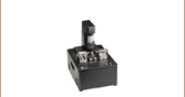
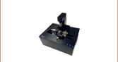
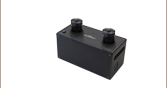
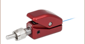
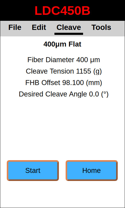
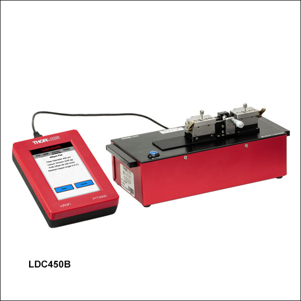
LDC450B
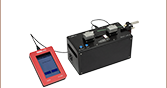
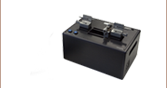
Portable Large-Diameter Fiber Cleaver
Top and Bottom Fiber Holder Inserts
(Must be Purchased Separately)
Included Handheld Controller Provides Easy-to-Use Interface
VHA25
VHE25


Please Wait

Click to Enlarge
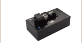
Figure 1.1 A close-up of the cleave assembly on the LDC450B. A clamping screw on the top of each holding block can be tightened to provide extra clamping force for gripping fibers with outer diameters ≥500 µm. Magnets in each holding block provide sufficient force for clamping smaller fiber diameters.
Features
- Cleave Glass Fibers with Claddings from Ø200 µm to Ø800 µm
- Flat Cleaves
- Programmable Processes for a Wide Variety of Fibers:
- Single Mode, Multimode, and Polarization-Maintaining Fibers
- Capillary Tubes
- Photonic Crystal Fiber (PCF)
- Microstructured Fibers
- Non-Circular Fibers
- Handheld Controller for Setting Cleave Parameters (See Controller Tab for Details)
- Replacement Components Sold Separately Below
- Fiber Holding Blocks and Fiber Holder Inserts Shared with Other Systems for Ease of Transfer Between Processes:
Build Your System
- Large-Diameter Fiber Cleaver for Fibers with Claddings from Ø200 µm to Ø800 µm
- Choose Top and Bottom Inserts (Two Top Inserts and Two Bottom Inserts are Required;
See Fiber Holder Inserts Tab for More Information)
The LDC450B Portable Large-Diameter Fiber Cleaver precisely cleaves fibers with claddings from 200 µm to 800 µm in diameter, and is designed to produce flat cleaves perpendicular to the length of the fiber. For ease of use and versatility in both manufacturing and research environments, this fiber cleaver features a rechargeable battery and includes our VYT300C Handheld Controller.
The cleaver uses the "tension-and-scribe" cleaving process, where tension is applied along the length of the fiber followed by an automatic scribing process utilizing a diamond cleave blade. After the blade scribes the fiber, tension is maintained, causing the scribe to propagate across the fiber width and complete the cleave. The cleaver also has settings to carry out an automated "sub-critical" scribe process designed to improve the cleave quality in specialty fibers, such as photonic crystal fiber (PCF), microstructured fibers, capillary tubes, or highly stressed fibers (multimode or polarization maintaining). The cleaver is equipped with a flat-tipped micrometer backstop, which can help improve end-face quality when performing low-tension cleaves. See the Cleaving Guide tab for details.
The cleaver uses a diamond blade for scribing the fiber. When used with proper cleave parameters, a single location on the blade can provide up to 5,000 cleaves (dependent on the cladding properties of the fiber being cleaved). The cleaver is designed so that the cleave blade can be repositioned approximately nine times before replacement (assuming proper cleave parameters and usage that does not cause unexpected damage to the blade). We only recommend using these cleavers with fibers that have a glass cladding; other materials, such as plastic, will rapidly degrade or damage the blade. Replacement blades are available separately below.
Accessories
The LDC450B cleaver is designed to accept Fiber Holder Inserts that can clamp a variety of outer diameters. Our selection of top and bottom inserts are available separately below, listed with the maximum fiber sizes accepted by each insert. The Fiber Holder Inserts tab has a selection guide to aid in choosing which pairs of fiber holder inserts are required, based on the diameter of the fiber to be cleaved, as well as to aid to install them in the fiber holding blocks. Two top and two bottom inserts are required to operate the fiber cleaver.
To cleave Ø80 µm to Ø1.25 mm fibers, Thorlabs offers the LDC401 and LDC401A Large-Diameter Fiber Cleavers, which produce flat and angled cleaves, respectively. Both are equipped with a vacuum pump to aid in positioning smaller fibers with diameters <200 µm. In addition to the portable large-diameter fiber cleaver, we offer the FPS301 Stripping and Cleaning Station, FCA750 Fiber Cleave Analyzer, the LFS4100 Fiber Splicer, GPX4000LZ CO2 Laser Glass Processor, and the GPX3400 and GPX3600 Glass Fiber Processing Stations. Many of the fiber holder inserts that are compatible with the LDC450B cleaver are also compatible with these other fiber processing and measurement systems, making it easy to move the fiber between stations.
| Compatible Vytran Fiber Processing Systems | |||||||
|---|---|---|---|---|---|---|---|
| Fiber Preparation Station (Strip and Clean) |
Large-Diameter Fiber Cleavers | Portable Large-Diameter Fiber Cleaver | Large-Diameter Fiber Splicer | CO2 Laser Glass Processing System (Splice and Taper) |
Automated Glass Processing Systems with Integrated Cleaver (Cleave, Splice, and Taper) |
Automated Glass Processing Systems (Splice and Taper) |
Recoaters and Proof Testers |
| Specifications | |
|---|---|
| Item # | LDC450B |
| Cleave Type | Flat Cleave |
| Accepted Fiber Sizes | Cladding: Ø200 µm to Ø800 µm Buffer: Ø250 µm to Ø3.2 mm |
| Accepted Fiber Types | SM, PM, MM, Specialty Fibers Including Photonic Crystal Fiber (PCF) and Non-Circular Fiber, and Capillary Tubes |
| Cleave Method | Tension and Scribe |
| Cleave Tolerance | ±0.5° for ≤400 µm Cladding Diameter ±1.0° for >400 µm Cladding Diameter |
| Loading | Linear Tension, Stepper Motor Controlled |
| Tension | 63.7 N (14.3 lbs) Max, Programmablea |
| Scribe | Diamond Blade, Stepper Motor Controlled |
| V-Groove Inserts | Available Separately (See Below) |
| Power | 12.5 VDC, 5 A (Provided by External Power Supply) |
| External Power Supply | 100 - 120 / 200 - 240 VAC, 4.5 / 2.2 A, 47 - 63 Hz |
| Dimensions (L x W x H) without Holding Blocks | 10.63" x 4.64" x 2.91" (269.9 mm x 117.7 mm x 73.8 mm) |
| Dimensions (L x W x H) | 10.63 " x 4.64" x 4.48" (269.9 mm x 117.7 mm x 113.7 mm) |
| Weight | 5.5 lbs (2.5 kg) |
| Operating Temperature | 15 to 40 °C |
| Altitude Range | 0 to 2000 m Above Sea Level |
| Operating Humidity | 0% to 75% Relative Humidity (Non-Condensing) |
| Storage Temperature | -20 to 60 °C |
| Storage Humidity | 0% to 90% Relative Humidity (Non-Condensing) |
| Battery Life | 5.5 hours with Handset Controller Plugged in, 10 hours with Handset Controller Unplugged |
Programmable Cleave Parameters
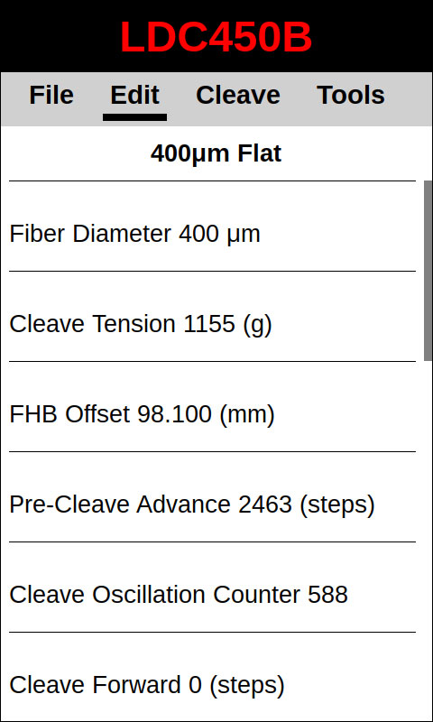
This portable, large-diameter fiber cleaver is designed to provide easy operation when performing simple cleaves but still support customized processing for more complicated cleaves involving specialty fibers. A complete list of modifiable parameters is listed in the Handset Controller Cleave Parameter Definitions. The majority of users will only need to enter the Fiber Diameter (cladding), Cleave Tension, and Pre-Cleave Advance while leaving the rest of the parameters set to their default values. To further simplify the process, the handset controller features an autoset function that will estimate an appropriate Cleave Tension and Pre-Cleave Advance based on the fiber diameter, although these values can be adjusted by the user if necessary.
| Fiber Cleaver Parameter Limits | |||
|---|---|---|---|
| Parameter | Default | Minimum | Maximum |
| Fiber Diameter | Fiber Size Dependent |
10 µm | 1500 µm |
| Cleave Tensiona,b | Fiber Size Dependent |
1 g | 6500 g |
| Pre-Cleave Advance | Fiber Size Dependent |
200 Steps (300 µm) |
400 Steps (600 µm) |
| Set FHB Offset | 0 mm | 0 mm | 47 mm |
| Tension Velocity | 60 Steps/s (48 µm/s) |
4 Steps/s (3.2 µm/s) |
200 Steps/s (160 µm/s) |
| Cleave Peck Cycles | 60 | 10 | 250 |
| Cleave Forward Steps | 81 | 40 | 400 |
| Cleave Reverse Steps | 80 | 39 | 399 |
| Scribe Delay | 250 ms | 1 ms | 5000 ms |
| Set Blade Offset | Unit Specific Value |
100 Steps (150 µm) |
2500 Steps (3750 µm) |
| Sub-Critical Process Parametersc | |||
| Re-Tension Levela,d | 10 g | 1 g | 100 g |
| Post-Scribe Pause | 1.0 s | 0.1 s | 30.0 s |
| Re-Tension Pause | 1.0 s | 0.1 s | 30.0 s |
| Re-Tension Limit | 20% of Cleave Tension |
1% of Cleave Tension |
50% of Cleave Tension |
Handset Controller Cleave Parameter Definitions
The definition of each of the parameters that can be entered into the handset controller are described here.
Fiber Diameter: The diameter of the fiber cladding. This is also the fiber cleave parameter file name.
Cleave Tension: The load applied axially to the fiber prior to initiating the scribe process. These cleavers are calibrated using standard weights that are hung off of a pulley, so the tension settings are programmed into the handset controller in grams. Possible settings correspond to a range of tensions from 9.8 mN (0.0022 lbs) to 63.7 N (14.3 lbs).
Pre-Cleave Advance: Before cleaving, the cleave blade must move closer to the fiber. The location of the blade just prior to cleaving is set using this parameter. One step corresponds to 0.00006" (1.5 µm).
Set FHB Offset: This stands for "Set Fiber Holding Block Offset". It is the distance that the left fiber holding block will be shifted to the left from the "home" position prior to loading the fiber. This allows the user to adjust the distance between the edge of the holding block and the cleave point.
Tension Velocity: The speed at which tension is applied to the fiber prior to cleaving. One step corresponds to 0.00003125" (0.8 µm).
Cleave Peck Cycles: To properly cleave the fiber, the cleave blade will ideally make one single, quick contact with the fiber. In order to achieve this, the blade will begin to oscillate forward and backwards after the pre-cleave advance distance has been traveled. This parameter sets the total number of oscillations that will occur during the cleave process.
Cleave Forward Steps: This parameter controls how far the blade moves towards the fiber during the "forward" portion of the cleave peck cycle. One step corresponds to 0.00006" (1.5 µm).
Cleave Reverse Steps: This parameter controls how far the blade moves away from the fiber during the "backward" portion of the cleave peck cycle. One step corresponds to 0.00006" (1.5 µm).
Scribe Delay: This is the delay in milliseconds between each cleave peck cycle. It provides time for the scribe to propagate across the fiber, completing the cleave, before the blade moves forward again. This helps prevent the blade from contacting the fiber more than once.
Set Blade Offset: Adjusts the position that the blade returns to after homing. This allows the starting point for the pre-cleave advance and subsequent cleave peck cycles to be globally adjusted. One step corresponds to 0.00006" (1.5 µm).
Special Sub-Critical Process Parameters
During the Sub-Critical Process, additional tension is applied to the fiber after the scribe occurs.
Post-Scribe Pause: The time, in seconds, between the last oscillation of the cleave blade and the first increase in tension applied to the fiber.
Re-Tension Pause: The time between subsequent increases in the tension applied to the fiber (all increases in tension after the first one, which occurs after the Post-Scribe Pause).
Re-Tension Level: The tension is increased incrementally after the scribe. This is the amount by which the tension is increased after the Post-Scribe Pause and each Re-Tension Pause. These cleavers are calibrated using standards weights that are hung off of a pulley, so the tension settings are programmed into the handset controller in grams. Possible settings correspond to a range of tensions from 9.8 mN (0.0022 lbs) to 0.98 N (0.22 lbs).
Re-Tension Limit: The maximum amount of additional tension that will be applied to the fiber as a percentage of the original tension.
Fiber Holder Insert Selection Guide
Introduction
Fiber Holder Inserts, which are designed to hold various sized fibers within the cleaver, must be purchased separately. The bottom inserts have V-grooves to hold the fiber, while the top inserts each feature a recessed, flat surface that clamps the fiber against the V-groove in the bottom insert. Each top and bottom insert is sold individually, as the fiber diameter clamped by the left and right holding blocks may not be the same. Two top inserts and two bottom inserts are required to operate the cleaver.
Table 3.3 indicates the maximum and minimum diameters that can be accommodated by different combinations of top and bottom inserts. It also indicates how far offset the fiber will be for recommended combinations of top and bottom inserts. Note that the fiber outer diameter may be the fiber cladding, jacket, or buffer. If one side of the fiber is being discarded, it is preferable to clamp onto the cladding of this section except in special cases (such as non-circular fiber) where the coating or buffer may be preferable. Sections of fiber that are not being discarded should always be clamped on the coating or buffer in order to avoid damaging the glass. This may require different sets of fiber holder inserts to be used in the left and right holding blocks. In this case, it is important to minimize the difference in the offsets introduced by the left and right sets of inserts when attempting to produce perpendicular, flat cleaves.
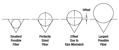
Figure 3.1 Each V-groove can accommodate a range of fiber sizes.
| Table 3.2 Legend | ||
|---|---|---|
|
|
Best Fit | |
|
|
Second Best Fit: Try these options if the best fit does not incorporate your fiber sizes. | |
|
|
Third Best Fit: Try these options if the other two categories do not incorporate your fiber sizes. | |
Fiber Holder Insert Selection Chart
- First, select the bottom insert that matches your fiber size most closely.
Example: For an Ø800 µm fiber, the VHD750 insert is the closest match, since it is only 50 µm smaller. - On Table 3.3, look to the right of your chosen bottom insert. Select a compatible top insert based on the fiber diameter size range shown in each cell.
Example: For the Ø800 µm example fiber from step 1, the green cell is in the 750 µm groove column for the VHA05 top insert which has two grooves. The numbers listed in the green cell indicate that this combination of inserts is good for fibers from 728 to 963 µm in diameter. Our Ø800 µm fiber is within this range, so this is a good choice. There are several other options as well that will accommodate an Ø800 µm fiber as well, but the green shading in the chart indicates that the 750 µm groove in the VHA05 provides the best fit. - The second line of numbers in each cell shows the range of offsets that can be expected for any given combination of top and bottom inserts. When selecting inserts for the right and left fiber holding blocks, try to minimize the offsets between the pairs of inserts on each side.
Example: If we choose a VHD750 bottom insert and the Ø750 µm groove in the VHA05 top insert, we can use fiber as small as 728 µm, in which case the center of the fiber would sit 23 µm below the surface of the bottom insert. We could also clamp a fiber as large as 963 µm, in which case the center of the fiber would sit 213 µm above the surface of the bottom insert. We could interpolate to find the offset experienced by our hypothetical 800 µm fiber, but it turns out that in the 60° V-groove on these inserts, the offset is equal to the diameter difference. So in our example, that means that the center of our fiber is going to sit 50 µm above the bottom insert surface, since it is 50 µm larger than the fiber that the bottom insert was designed for (800 - 750 = 50). - Fiber holder inserts designed for fibers smaller than Ø1000 µm have vacuum holes that, when used with a Vytran system that includes a vacuum pump for the fiber holding blocks, can aid in aligning small fibers within the groove. Note that the LDC450B does not include a vacuum pump, and therefore, does not take advantage of this feature. Inserts with vacuum holes are indicated by a superscript "b" in Table 3.3.
| Table 3.3 Fiber Holder Inserts Selection Guide | |||||||||||||
|---|---|---|---|---|---|---|---|---|---|---|---|---|---|
| Top Insert Item # | VHA00a | VHA05a | VHA10a | VHA15a | VHA20a | VHA25 | VHA30 | ||||||
| Accepted Diameter (Nominal) | ≤320 µm | 400 µm | 500 µm | 750 µm | 1000 µm | 1250 µm | 1500 µm | 1750 µm | 2000 µm | 2250 µm | 2500 µm | 3000 µm | |
| Bottom Insert Item # |
Accepted Diameter (Nominal) |
Min / Max Accepted Fiber Diameter (µm) Min / Max Fiber Offset (µm) |
|||||||||||
| VHD160b or VHF160b,c |
160 µm | 112 / 208 -49 / 48 |
- | - | - | - | - | - | - | - | - | - | - |
| VHD250b or VHF250b,c |
250 µm | 177 / 320 -73 / 69 |
275 / 323 25 / 74 |
- | - | - | - | - | - | - | - | - | - |
| VHD400b or VHF400b,c |
400 µm | 279 / 519 -122 / 119 |
377 / 517 -23 / 117 |
410 / 519 -9 / 119 |
- | - | - | - | - | - | - | - | - |
| VHD500b or VHF500b,c |
500 µm | 346 / 592 -153 / 93 |
447 / 647 -53 / 147 |
476 / 711 -24 / 211 |
560 / 795 61 / 296 |
- | - | - | - | - | - | - | - |
| VHD750b or VHF750b,c |
750 µm | 516 / 759 -234 / 9 |
617 / 970 -132 / 221 |
643 / 878 -107 / 128 |
728 / 963 -23 / 213 |
812 / 1047 62 / 297 |
- | - | - | - | - | - | - |
| VHE10a | 1000 µm | - | - | 773 / 1008 -172 / 63 |
858 / 1093 -88 / 147 |
943 / 1178 -3 / 232 |
1036 / 1271 90 / 325 |
- | - | - | - | - | - |
| 1250 µm | - | - | - | 1034 / 1269 -176 / 59 |
1119 / 1354 -91 / 144 |
1212 / 1447 2 / 237 |
1288 / 1523 78 / 313 |
- | - | - | - | - | |
| VHE15a | 1500 µm | - | - | - | - | 1280 / 1515 -172 / 63 |
1373 / 1608 -79 / 156 |
1449 / 1684 -2 / 233 |
1534 / 1769 82 / 314 |
- | - | - | - |
| 1750 µm | - | - | - | - | - | 1534 / 1770 -159 / 76 |
1611 / 1846 -83 / 152 |
1695 / 1930 2 / 237 |
1772 / 2007 78 / 313 |
- | - | - | |
| VHE20a | 2000 µm | - | - | - | - | - | - | 1787 / 2022 -171 / 64 |
1871 / 2106 -86 / 149 |
1947 / 2183 -10 / 225 |
2032 / 2267 74 / 309 |
- | - |
| 2250 µm | - | - | - | - | - | - | - | 2033 / 2268 -167 / 68 |
2109 / 2344 -91 / 144 |
2193 / 2429 -6 / 229 |
2278 / 2513 78 / 313 |
- | |
| VHE25 | 2500 µm | - | - | - | - | - | - | - | - | 2270 / 2505 -172 / 64 |
2355 / 2590 -87 / 148 |
2439 / 2675 -2 / 233 |
2609 / 2844 167 / 402 |
| VHE30 | 3000 µm | - | - | - | - | - | - | - | - | - | 2692 / 2944 -256 / -4 |
2777 / 3029 -171 / 81 |
2946 / 3198 -2 / 250 |
Fiber Holder Assembly and Installation
After you select the correct fiber insert for your nominal fiber diameter, the fiber inserts need to be installed into the fiber holding blocks, as shown in Video 3.4. Standard fiber inserts are meant to remain installed in a system when processing fibers of the same size, while fiber transfer inserts are used to move a fiber from one compatible Vytran machine to another between processing steps. Transfer inserts consist of a fiber holder bottom insert, fiber transfer clamp, and graphite V-grooves that require assembly as shown in Video 3.5.
Handset Controller GUI Interface
The VYT300C handset controller is included with the LDC450B portable, large-diameter fiber cleaver. This controller is also compatible with the LDC401 and LDC401A Vytran large-diameter fiber cleavers, as well as Vytran PTR fiber recoaters and proof testers. One handset controller can be used to configure parameters on multiple fiber processing units in succession. Full instructions for using the handset controller can be found in the manual. The screenshots in Figures 4.1 through 4.6 highlight key features of the graphical user interface.
Click to Enlarge
Figure 4.1 The initial screen on VYT300C handset controller prompts the user to load the fiber, as well as providing the options to start a cleave with the displayed parameters and to home the fiber holding blocks. Other menus can be accessed by swiping the touchscreen left or right, or by tapping the options at the top of the screen.
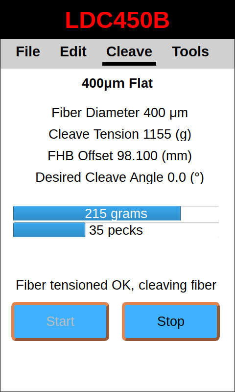
Click to Enlarge
Figure 4.2 During a cleave, the handset controller monitors the cleave tension and the number of cleave peck cycles. It also displays parameters defined in the edit tab.
Click to Enlarge
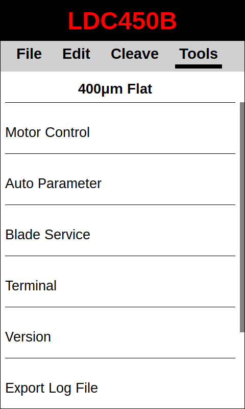
Figure 4.3 The Tools Screen provides several utilities that are used for maintenance or troubleshooting.
Click to Enlarge
Figure 4.4 The Edit menu shows parameters that can be configured by the user. These parameters are the same as those that can be edited using the tablet controller.
Click to Enlarge
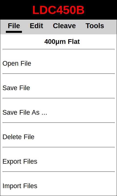
Figure 4.5 The handset controller can open, save, delete, export, and import files containing parameters for compatible systems. Exporting or importing a file will require a memory device to be connected to the Program Port of the handset controller.
Click to Enlarge
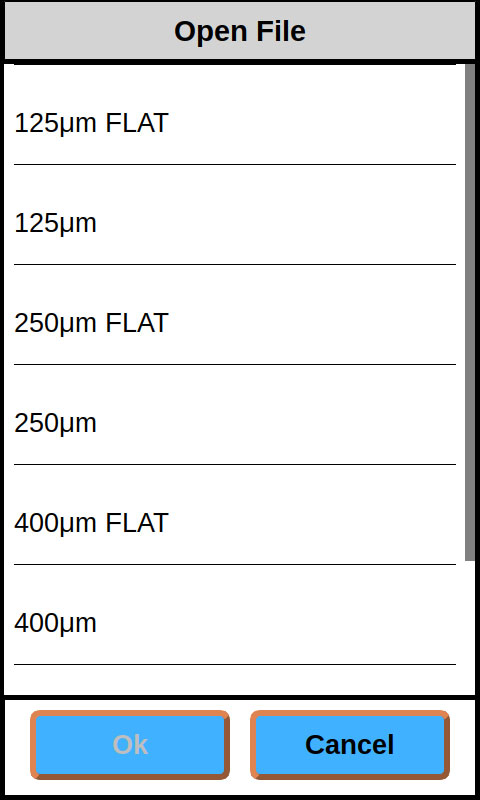
Figure 4.6 Fiber files can be saved onto the internal storage of the handset controller.
Tutorial Videos
To assist new or returning LDC users with operating their cleavers, we have created a series of tutorials aimed at teaching the basic skills needed to run this machine including setting up the device, installing inserts, and performing a flat cleave or angled cleave. These processes are demonstrated using an LDC401 cleaver, however, the procedures are identical for the LDC401A and LDC450B cleavers. Additionally, angled cleaves can only be performed using the LDC401A cleaver due to the rotation module included in that system. In order to be able to read the text in the videos, we strongly recommend viewing these videos at full screen, 1080p resolution. If you require assistance using your LDC fiber cleaver, please contact us at techsupport@thorlabs.com.
Tension-and-Scribe Cleave Process
Click to Enlarge
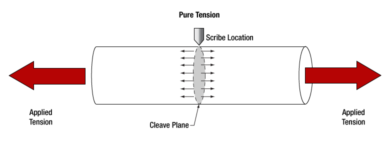
Figure 6.1 An illustration of the tension-and-scribe method as used by the LDC450B cleaver to produce a flat cleave. Tension is applied along the optical axis of the fiber prior to cleaving. A diamond blade then scribes the fiber, and the tension causes the scribe to propagate across the fiber in a plane that is orthogonal to the direction of the tension.
Tension-and-Scribe Cleave Process
The LDC450B cleaver use the "tension-and-scribe" cleaving process, where tension is applied along the length of the fiber followed by an automatic scribing process utilizing a diamond blade. After the blade scribes the fiber, tension is maintained, causing the scribe to propagate across the fiber width and complete the cleave.
Sub-Critical Process for Cleaving Specialty Fibers
Certain specialty fibers, such as photonic crystal fiber (PCF), microstructured fibers, capillary tubes, or highly stressed fibers (multimode or polarization maintaining) may require special parameters in order to create clean cleaves at the desired angle. These Vytran® fiber cleavers can be programmed with a "sub-critical" cleave process in order to produce high-quality cleaves for these fiber types.
For these cleaves, the initial tension applied to the fiber is lower than what would be required for the standard "tension-and-scribe" process. The included micrometer backstop prevents the fiber from bending when it is scribed at this lower tension. After the scribe, the tension is slowly, incrementally increased, which serves to propagate the scribe across the fiber and complete the cleave. Parameters for this process can be adjusted using the handset controller, including the starting and ending tension and how fast the tension is increased after the initial scribe.
Cleaving Guide
The following information is intended to provide a starting point when selecting the best process to use for cleaving different types of fiber. To achieve the best possible cleave results, further experimentation is typically required to fine-tune the cleave parameters for each specific fiber type.
Standard Process: The tension-and-scribe method where a constant tension is applied to the fiber, the fiber is scribed, and the tension causes the scribe to propagate across the fiber to produce the cleave. To see a walk-through on how to perform a tension-and-scribe flat cleave, see the Tutorial Videos tab.
Sub-Critical Process: This process starts with a lower tension applied to the fiber than required by the standard cleaving process. After the fiber is scribed, the tension is slowly increased until the scribe propagates across the fiber and the cleave is complete. This can improve the cleave quality in highly stressed or specialty fibers.
Micrometer Backstop: The tip of the micrometer is positioned so that it just touches the fiber, providing a surface that prevents the fiber from deforming when contacted by the cleave blade during scribing. It is particularly useful when cleaving large-diameter fibers or when using the lower-tension sub-critical process.
| Fiber Type | Standard Process | Sub-Critical Process | Micrometer Backstop |
|---|---|---|---|
| Single Mode Fiber | - | - | |
| Multimode Fiber | - | - | |
| Thick-Walled Capillary Tubing (Wall Thickness at Least 10% of Diameter) |
- | - | |
| Thin-Walled Capillary Tubing (Wall Thickness <10% of Diameter) |
- | ||
| PM Fiber, Fiber Cladding ≤Ø400 µm | - | ||
| PM Fiber, Fiber Cladding >Ø400 µm | - | ||
| PCF | - |
 Product DemonstrationsThorlabs has demonstration facilities for the Vytran® fiber glass processing systems offered on this page within our Morganville, New Jersey; Shanghai, China; and Exeter, Devonshire offices. We invite you to schedule a visit to see these products in operation and to discuss the various options with a fiber processing specialist. Please schedule a demonstration at one of our locations below by contacting technical support. We welcome the opportunity for personal interaction during your visit! Thorlabs Vytran Europe
|
.jpg)
| Posted Comments: | |
| No Comments Posted |

 Zoom
ZoomComponents
Included
- LDC450B
- Handset Controller
- USB Y-Cable
- 12 V Power Supply
- Location-Specific AC Power Cord
- Nylon Brush
- Tweezers
- 0.035", 0.050", and 3/32" Hex Keys
Must be Purchased Separately
- Fiber Holder Top Inserts (Two Required)
- Fiber Holder Bottom Inserts (Two Required)
Optional Accessories (Sold Separately)
- Replacement Diamond Cleave Blade
- Replacement SS2SN013 Setscrews for Fiber Holding Blocks
- Flat Cleaves Fibers with Claddings from Ø200 µm to Ø800 µm
- Accepts SM, MM, PM, and Specialty Fibers
- Includes Micrometer Backstop to Support Low-Tension Cleave Processes
- Diamond Cleave Blade
- Fiber Holder Inserts Must be Purchased Separately (Available Below)
The Vytran LDC450B Portable Large-Diameter Fiber Cleaver produces high-quality, flat cleaves in fibers with claddings from Ø200 µm to Ø800 µm in order to support precision splicing applications. This cleaver features a diamond cleave blade, a micrometer backstop that enables low-tension cleaves in specialty fibers, and a ruler block and translating fiber holding block to align the point to be cleaved. For ease of use and versatility in both manufacturing and research environments, this fiber cleaver features a rechargeable battery and includes our VYT300C Handheld Controller.
The left fiber holding block is connected to the same motorized stage as is used in our linear proof testers and includes a load cell that allows the system to internally monitor the tension applied to the fiber during the cleave process. The position of this holding block can be adjusted prior to cleaving by entering the desired position, with micron-level precision, into the handset controller (display units are in millimeters).
The VYT300C handset controller included with each cleaver allows the parameters of the cleave process to be precisely controlled. Adjustable settings include the fiber tension, velocity at which the tension is applied to the fiber, how quickly the scribe approaches the fiber, and fiber diameter. The handset controller is shipped preloaded with five files for common cleave parameters. See the Controllers tab for details.
Click to Enlarge
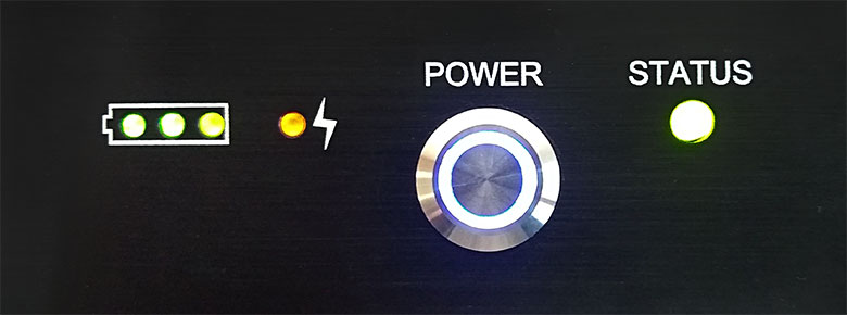
Figure G1.1 Status Indicator LEDs on the LDC450B Cleaver
Once the desired cleave parameters are set and loaded into the cleaver, the handset controller can be removed and the cleaving process initiated by pressing the blue button on the top of the unit. For manufacturing environments with multiple cleaving stations, this feature streamlines the production process by allowing the same cleave parameters to be easily loaded into multiple LDC450B cleavers.
Ideal for manufacturing environments, the LDC450B features a rechargeable battery that has a lifetime of 5.5 hours with the handset controller plugged in and 10 hours with the handset controller unplugged. Several indicator LEDs are included on the housing to display the status of the cleaver; see Figure G1.1. Three green lights in a battery icon indicate the battery level of the unit, an orange LED next to a lightning icon indicates that the battery is charging, and a halo around the power button means the unit is on. The status LED changes based on the state of the unit; please see the manual for details.
These cleavers use fiber holding blocks that are compatible with the FPS301 Stripping and Cleaning Station, LFS4100 Fiber Splicer, GPX3000 Glass Fiber Processing Stations, and GPX4000LZ CO2 Laser Glass Processor, allowing fiber to be moved easily between systems. Fiber Holder Inserts are available below in a variety of sizes and must be purchased separately. Nylon-tipped setscrews are used to secure the inserts in the fiber holding blocks; replacement 2-56, 1/8" long SS2SN013 setscrews are available in packs of 10. A selection guide is provided on the Fiber Holder Inserts tab to aid in determining which inserts are appropriate for the fiber to be cleaved and to show how inserts are installed in the unit.
Each unit is shipped with a power supply and location-specific power cord.
The LDC450B cleaver does not include an internal vacuum pump, making it suitable only for fibers with diameters ≥200 µm. To cleave fibers with smaller diameters, our LDC401 and LDC401A cleavers with vacuum-assisted loading should be used.

 Zoom
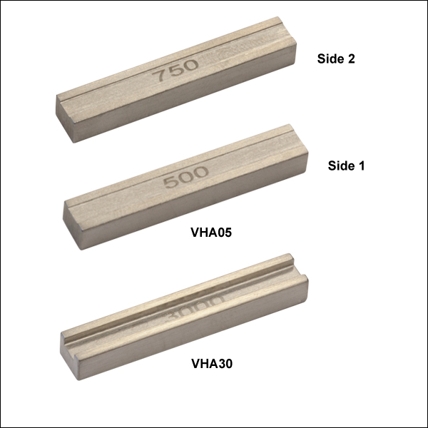
Zoom| Fiber Holder Top Insertsa | ||
|---|---|---|
| Item # | Side 1 Min/Max Accepted Diameter |
Side 2 Min/Max Accepted Diameter |
| VHA00 | 57 µm / 759 µmb | 275 µm / 970 µm |
| VHA05 | 410 µm / 1008 µm | 560 µm / 1269 µm |
| VHA10 | 812 µm / 1515 µm | 1036 µm / 1770 µm |
| VHA15 | 1288 µm / 2022 µm | 1534 µm / 2268 µm |
| VHA20 | 1772 µm / 2505 µm | 2032 µm / 2944 µm |
| VHA25 | 2278 µm / 3029 µm | N/A |
| VHA30 | 2609 µm / 3198 µm | N/A |
- Two are Required to use the Portable Large-Diameter Fiber Cleaver
- Flat, Recessed Surface Clamps the Fiber Against the V-Groove in the Bottom Insert (Sold Below)
- Clamp Outer Diameters from 112 µm to 3.198 mm When Used with Bottom Inserts
- Compatible with Other Vytran Systems
- Interchangeable by the User
The portable large-diameter fiber cleaver requires a pair of Top and Bottom Fiber Holder Inserts to be placed in each of the fiber holding blocks in order to clamp the fiber during the cleaving process. Each top insert consists of a bar that has a recessed area on one or both sides, designed to clamp the fiber against the V-groove in a bottom insert. The inserts sit in the top section of the fiber holding blocks and are available in a variety of groove sizes. Top inserts are sold individually, and two are required to use these cleavers.
The top and bottom inserts (available below) can be paired in different combinations, outlined on the Fiber Holder Inserts tab, to accommodate fiber with outer diameters from 112 µm to 3.198 mm.
While the portable large-diameter fiber cleavers can only cleave fibers with cladding diameters from 200 µm up to 800 µm, we offer inserts that can accommodate larger outer diameters as there are cases where the fiber should be clamped on the coating instead of the cladding. During a typical cleave, it is often desirable to clamp the cladding on the side to be discarded and the coating on the side of the fiber that will be retained. Alternatively, the fiber may be center stripped and the coating clamped on both sides (preferable in some cases, such as creating a firm clamp on non-circular fiber). Therefore, multiple combinations of top and bottom inserts may be required to accommodate all of the diameters that need to be clamped. The Fiber Holder Insert tab includes information to aid in selecting and installing the correct combinations of top and bottom inserts to accommodate different fiber diameters.

 Zoom
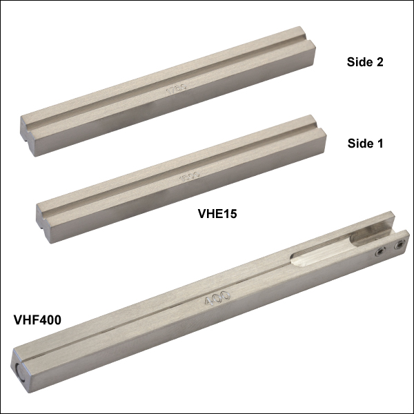
Zoom| Table G3.1 Fiber Holder Bottom Insertsa | |||||
|---|---|---|---|---|---|
| Item # | Transfer Insert |
Side 1 Min/Max Accepted Diameter |
Side 2 Min/Max Accepted Diameter |
Vacuum Holes |
|
| VHD160 | No | 112 µm / 208 µm | N/A | Yes | |
| VHF160 | Yesb | ||||
| VHD250 | No | 177 µm / 323 µm | N/A | Yes | |
| VHF250 | Yesb | ||||
| VHD400 | No | 279 µm / 519 µm | N/A | Yes | |
| VHF400 | Yesb | ||||
| VHD500 | No | 346 µm / 795 µm | N/A | Yes | |
| VHF500 | Yesb | ||||
| VHD750 | No | 516 µm / 1047 µm | N/A | Yes | |
| VHF750 | Yesb | ||||
| VHE10 | No | 773 µm / 1271 µm | 1034 µm / 1523 µm | No | |
| VHE15 | No | 1280 µm / 1769 µm | 1534 µm / 2007 µm | No | |
| VHE20 | No | 1787 µm / 2267 µm | 2033 µm / 2513 µm | No | |
| VHE25 | No | 2270 µm / 2844 µm | N/A | No | |
| VHE30 | No | 2692 µm / 3198 µm | N/A | No | |
- Two are Required to Use the LDC450B
- Clamp Outer Diameters from 112 µm to 3.198 mm when Used with Top Inserts (Available Above)
- VHF Transfer Inserts are Used with VHT1 Transfer Clamp to Aid in Transferring a Fiber with ≤Ø1.047 mm Coating between Compatible Systems:
- Interchangeable by the User
The large-diameter fiber cleaver requires a pair of Top and Bottom Fiber Holder Inserts to be placed in each of the fiber holding blocks in order to clamp the fiber during the cleaving process. Each bottom insert has a V-Groove on one or both sides that can accommodate a range of diameters (as indicated in Table G3.1).
Three types of bottom inserts are available for the portable large-diameter fiber cleaver. Standard bottom inserts for fiber with an outer diameter <Ø1.047 mm have vacuum holes; note that the LDC450B cleaver is not equipped with a vacuum pump, and this feature is for other compatible Vytran systems. For certain fiber diameters, we also offer transfer inserts (Item #s beginning with VHF) designed to work with the VHT1 transfer clamps (available below) that aid in moving the fiber between compatible Vytran stations while maintaining coarse alignment. The VHE series of fiber holder bottom inserts have a V-Groove on one (VHE25 and VHE30) or both sides (VHE10, VHE15, and VHE20) but do not include vacuum holes. The VHF transfer inserts and VHE bottom inserts can both be installed in other, compatible stations, although the VHE bottom inserts cannot be used with the VHT1 transfer clamp.
Bottom inserts are sold individually, and two are required to use the large-diameter cleaver. If using the fiber cleaver as a stand-alone device, the VHD series or the VHE series inserts will be sufficient. If using the cleavers with other compatible systems, the bottom insert in the left fiber holding block can be replaced with a transfer insert and VHT1 transfer clamp (available below) for certain fiber sizes, as indicated in Table G3.1. Typically, these transfer inserts would only be used in the left fiber holder block, as the right fiber holding block usually clamps the side of the fiber that will be discarded. The right fiber holding block of the LDC450B can accept transfer inserts, if desired.
The top (available above) and bottom fiber holder inserts can be paired in different combinations, outlined on the Fiber Holder Inserts tab above, to accommodate fiber with outer diameters from 112 µm to 3.198 mm. Though the LDC450B cleaver accepts fiber diameters from 200 to 800 µm, inserts that accommodate outer diameters >800 µm can also be used, as there are cases where the fiber should be clamped on the coating instead of the cladding. During a typical cleave, it is often desirable to clamp the cladding on the side to be discarded and the coating on the side of the fiber that will be retained. Alternatively, the fiber may be center stripped and the coating clamped on both sides (preferable in some cases, such as creating a firm clamp on non-circular fiber). Therefore, multiple combinations of top and bottom inserts may be required. The Fiber Holder Inserts tab above includes information to aid in selecting and installing the correct combinations of top and bottom inserts to accommodate different fiber diameters.

 Zoom
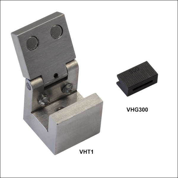
Zoom| Table G4.1 Graphite V-Groovesa | ||
|---|---|---|
| Item # | Accepted Diameter (Min / Max) |
Groove Length |
| VHG200 | 150 µm / 200 µm | 0.313" |
| VHG250 | 200 µm / 250 µm | 0.313" |
| VHG250L | 200 µm / 250 µm | 0.594" |
| VHG300 | 250 µm / 300 µm | 0.313" |
| VHG350 | 300 µm / 350 µm | 0.313" |
| VHG400 | 350 µm / 400 µm | 0.313" |
| VHG450 | 400 µm / 450 µm | 0.313" |
| VHG500 | 450 µm / 500 µm | 0.313" |
| VHG500L | 450 µm / 500 µm | 0.594" |
| VHG550 | 500 µm / 550 µm | 0.313" |
- Transfer Clamp and Graphite Tips for Fiber Holder Transfer Bottom Inserts
- Transfer Clamps Required to Transfer Fibers in VHF Inserts Between Compatible Systems
- Graphite V-Grooves for Supporting Fibers ≤Ø550 µm During Splicing or Tapering
- V-Grooves Accept Diameters from 150 µm to 550 µm
These Transfer Clamps and V-Grooves are used with the VHF Transfer Bottom Inserts sold directly above to move a single fiber between various systems with minimal loss of alignment. For example, a fiber can be placed in a transfer insert and cleaved using the LDC450B cleaver. Then, the entire transfer insert and fiber can be moved to a splicer or glass processor for splicing.
The VHT1 clamp secures transfer inserts with a magnetic lid that prevents axial movement of the fiber and can be used to hold the insert during transport without touching the fiber itself. For fibers with diameters ≤550 µm, a graphite V-groove is available to support the fiber when splicing (please see Table G4.1 for more information). To provide extended support along the length of the fiber and reduce the amount of overhang during processing, we also offer 0.594" long V-grooves (Item #'s VHG250L and VHG500L). The graphite V-grooves are secured by tightening two setscrews on the transfer insert. For information on how to assemble transfer inserts, see the Fiber Holder Inserts tab.

 Zoom
ZoomCompatible Systems
- CAC400 and CAC400A Fiber Cleavers
- LDC401 and LDC401A Fiber Cleavers
- LDC450B Portable Fiber Cleaver
- GPX3800, GPX3850, and GPX3900 Automated Glass Processors with Cleavers
- FFS2001 and FFS2001PT Fiber Preparation and Splicing Workstations
- FFS2001PM and FFS2001WS Fiber Preparation, Splicing,
and Proof Testing Workstations - Former Generation LDC-200 Fiber Cleaver
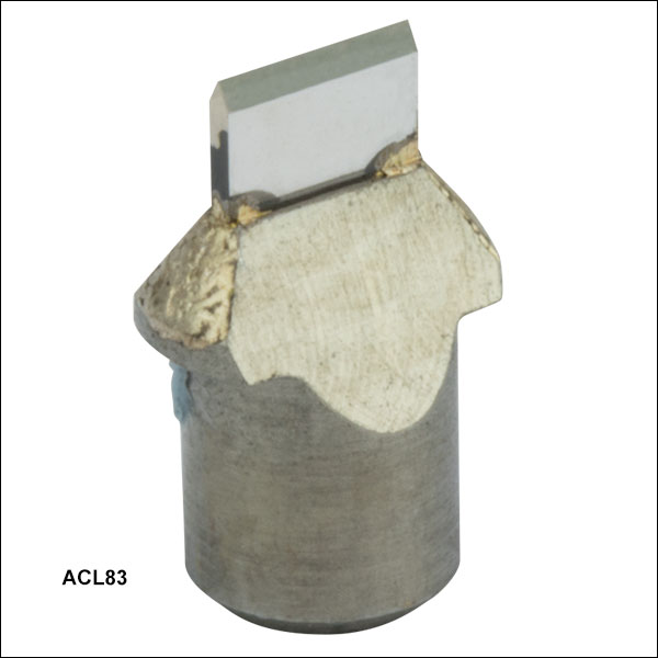
- Replacement Blade for Our Fiber Cleaving Systems (See List of Compatible Systems)
- 0.08" (2.0 mm) Long Diamond Blade
- User Installable
Click to Enlarge
Figure 540A The blade is shipped in a protective covering.
The ACL83 Diamond Cleave Blade is a replacement blade for the Vytran fiber processing systems in the Compatible Systems list. Each system is shipped with a blade included.
When used with proper cleave parameters, a single location on the blade can provide up to 5,000 cleaves (dependent on the cladding properties of the fiber being cleaved). The blade can be positioned approximately 10 times before replacement (assuming proper cleave parameters and usage that does not cause unexpected damage to the blade). Blade replacement instructions for each system are provided in the user manuals.
Note: Severe damage to the blade can occur if conditions cause high stress perpendicular to the edge of the blade or if incorrect parameters are used to cleave the fiber.