 Products Home / Lasers / Coherent Sources / Laser Diodes by Package & Type / Quantum Cascade Lasers: Fabry-Perot, HHL Packages
Quantum Cascade Lasers: Fabry-Perot, HHL Packages
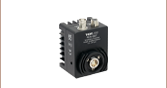
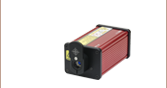
- Fabry-Perot QCLs in Thermoelectrically Cooled HHL Packages
- Center Wavelengths from 3.85 - 10.6 µm (2597 - 943 cm-1)
- Optical Output Powers Up to >1.5 W
- Custom Wavelengths, Packages, and Output Powers Available
Upon Request
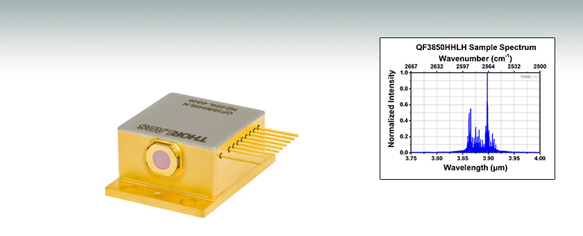
QF3850HHLH
3.85 µm CWL


Please Wait
| MIR Laser Types | |
|---|---|
| Fabry-Perot | TO Can |
| Two-Tab C-Mount | |
| D-Mount | |
| HHL | |
| Turnkey | |
| Distributed Feedback |
Two-Tab C-Mount |
| D-Mount | |
| HHL | |
| Turnkey | |
| Webpage Features | |
|---|---|
| Clicking this icon opens a window that contains specifications and mechanical drawings. | |
 |
Clicking this icon allows you to download our standard support documentation. |
|
Choose Item |
Clicking the words "Choose Item" opens a drop-down list containing all of the in-stock lasers around the desired center wavelength. The red icon next to the serial number then allows you to download L-I-V and spectral measurements for that serial-numbered device. |
Features
- Broadband Fabry-Perot Quantum Cascade Lasers (QCLs)
- Center Wavelengths from 3.85 - 10.6 µm (2597 - 943 cm-1)
- Horizontal, Collimated, Vertically Polarized Output
- High Heat Load Package Simplifies Thermal Management and System Integration
- Custom Wavelengths and Mounts Also Available (Contact Tech Sales for Details)
Thorlabs' Fabry-Perot Quantum Cascade Lasers (QCLs) exhibit broadband emission and the laser's specified output power is the sum over the full spectral bandwidth. Since these QCLs have broadband emission, they are well suited for medical imaging, MIR illumination, and microscopy applications. The QF3850HHLH, QF4040HHLH, and QF4650HHLH QCLs all have a typical spectral bandwidth from 60 - 80 nm. The QF6000HHLH and QF10600HHLH QCLs have a typical spectral bandwidth of 300 nm, while the QF9500HHLH QCL has a typical spectral bandwidth of 360 nm. The QF7900HB and QF8500HB QCLs have a typical spectral bandwidth of 500 nm, while the QF9200HB QCL has a typical spectral bandwidth of 1000 nm. The output spectrum, L-I-V curve, and beam propagation data of each serial-numbered device, measured by an automated test station before shipment, are available below and are also included on a data sheet that ships with the device.
Our QCLs emit a vertically polarized, collimated beam. At the output, a wedged, AR-coated zinc sulfide window prevents back reflections from returning to the laser chip, but also causes the beam to exit the mount at a 2.0 ± 0.6° angle (±0.75° for the QF7900HB, QF8500HB, and QF9200HB QCLs). A thermoelectric cooler and a thermistor are integrated into each laser for temperature control. The laser package is sealed, although the seal is not hermetic.
Although these lasers are specified for CW output, they are compatible with pulsed applications provided that the CW max operating current is not exceeded. These lasers do not have built-in monitor photodiodes and therefore cannot be operated in constant power mode. For more information or for custom options, please contact Tech Sales.
Mounts and Drivers
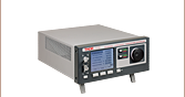
The QCLs on this page have operating voltages up to 15 V. We recommend using drivers such as our ITC4002QCL or ITC4005QCL Dual Current / Temperature Controller, which are rated to support this high operating voltage. See the Drivers tab for more information.
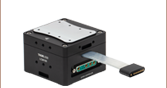
Thorlabs' HHL lasers are compatible with Thorlabs' LCM100(/M) Liquid-Cooled Mount or any other standard HHL mount. Thorlabs also offers cables for connecting HHL laser packages to the ITC4002QCL or ITC4005QCL Dual Current / Temperature Controller. The CAB4007A cable connects the LCM100(/M) mount to an ITC400xQCL controller while the CAB4007B cable directly connects a standard 10-pin HHL laser package to an ITC400xQCL controller. If designing your own mounting solution, note that due to these lasers' heat loads, we recommend that they be mounted in a thermally conductive housing to prevent heat buildup. Heat loads for Fabry-Perot QCLs can be up to 70 W (see the Handling tab for additional information).
Click to Enlarge
Maximum Output Power of Custom Fabry-Perot QCLs
High-Power OEM & Custom Lasers
Thorlabs manufactures custom and OEM quantum cascade lasers in high volumes. We maintain a broad chip inventory at our Jessup, Maryland, laser manufacturing facility and can reach multi-watt output on certain custom orders.
More details are available on the Custom & OEM Lasers tab. To inquire about pricing and availability, please contact us. A semiconductor specialist will contact you within 24 hours or the next business day.
Current and Temperature Controllers
Use Tables 2.1 and 2.2 to select a compatible controller for our MIR lasers. Table 2.1 lists the controllers with which the laser is compatible, and Table 2.2 contains selected information on each controller. Complete information on each controller is available in its full web presentation.
To get L-I-V and spectral measurements of a specific, serial-numbered device, click "Choose Item" next to the part number below, then click on the Docs Icon next to the serial number of the device.
Laser Mount and Cable Compatibility
Thorlabs' LCM100(/M) Liquid-Cooled Mount is specifically designed to be used with Thorlabs' HHL laser packages. The LCM100(/M) Mount is capable of dissipating heat loads up to 140 W at 25 °C, making it an ideal solution for temperature-controlled operation for all of Thorlabs' HHL lasers. For more details on the LCM100(/M) Liquid-Cooled Mount, please see its web presentation here.
The CAB4007B Dual Laser / TEC Connector Cable is designed to be used with any of Thorlabs' HHL laser packages or other HHL lasers with compatible pin settings. The CAB4007B connector cable is rated for up to 10 A of laser and TEC current. The CAB4007A Dual Laser / TEC Connector Cable is designed for use with the LCM100(/M) Mount and is rated for up to 11 A of laser and TEC current. For more details on the CAB4007x cables please see the full web presentation here. Please note that third party cables for these packages are typically not rated for the maximum current of the internal thermoelectric cooler.
If designing your own mounting solution, note that due to these lasers' heat loads, we recommend that they be secured in a thermally conductive housing with sufficient cooling capacity, either active or passive, to prevent heat buildup. The total heat loads for the Fabry-Perot QCL HHL package can be up to 70 W, although a typical heat load from a Fabry-Perot QCL itself is around 20 W.
| Table 2.1 Laser and Controller Compatibility | ||
|---|---|---|
| Laser Item # | Wavelength | Dual Current / Temperature Controllers |
| QF3850HHLH | 3.85 µm (2597 cm-1) |
ITC4002QCL, ITC4005QCL |
| QF4040HHLH | 4.04 µm (Typ.) (2475 cm-1) |
|
| QF4650HHLH | 4.65 µm (2151 cm-1) |
|
| QF6000HHLH | 6000 µm (1667 cm-1) |
|
| QF7900HB | 7.9 µm (1266 cm-1) |
|
| QF8500HB | 8.5 µm (1176 cm-1) |
|
| QF9200HB | 9.2 µm (Typ.) (1087 cm-1) |
|
| QF9500HHLH | 9500 µm (1053 cm-1) |
|
| QF10600HHLH | 10600 µm (943 cm-1) |
|
| Table 2.2 Controller Selection Guide | |||||
|---|---|---|---|---|---|
| Controller Item # | Controller Type | Controller Package | Current Range | Current Resolution | Voltage |
| ITC4002QCL | Current / Temperature | Large Benchtop (263 x 122 x 307 mm) |
0 to 2 A | 100 µA (Front Panel) 32 µA (Remote Control) |
17 V |
| ITC4005QCL | 0 to 5 A | 1 mA (Front Panel) 80 µA (Remote Control) |
20 V | ||
Do
|
Do Not
|
Handling High Heat Load Lasers
Proper precautions must be taken when handling and using high heat load lasers. Otherwise, permanent damage to the device will occur. Members of our Technical Support staff are available to discuss possible operation issues.
Avoid Static
Since these lasers are sensitive to electrostatic shock, they should always be handled using standard static avoidance practices.
Avoid Dust and Other Particulates
Contamination of the window must be avoided. Do not blow on the window or expose it to smoke, dust, oils, or adhesive films. The window is particularly sensitive to dust accumulation. During standard operation, dust can burn onto it, which will lead to premature degradation of the laser performance. If operating a high heat load laser for long periods of time outside a cleanroom, it should be sealed in a container to prevent dust accumulation.
Use a Current Source Specifically Designed for Lasers
These lasers should always be used with a high-quality constant current driver specifically designed for use with lasers. Lab-grade power supplies will not provide the low current noise required for stable operation, nor will they prevent current spikes that result in immediate and permanent damage.
Thermally Regulate the Laser
Temperature regulation is required to operate the laser for any amount of time. The temperature regulation apparatus should be rated to dissipate the maximum heat load that can be drawn by the laser. For our high heat load DFB QCLs and ICLs, this value is 38 W. For our high heat load Fabry-Perot QCLs, this value is 70 W.
The bottom face of the high heat load package is machined flat to make proper thermal contact with a heat sink. Ideally, the heat sink will be actively temperature regulated to ensure proper heat conduction. Thorlabs' LCM100(/M) Liquid Cooled Mount for HHL lasers is capable of dissipating >140 W of heat at 25 °C making it an ideal choice for temperature-controlled operation of HHL lasers. A fan may also serve to move the heat away from the package and prevent thermal runaway. However, the fan should not blow air on or at the laser itself. Thermal grease, pyrolytic graphite, and water cooling methods may also be employed for temperature regulation.
For assistance in picking a suitable temperature controller for your application, please contact Tech Support.
Carefully Make Electrical Connections
When making electrical connections, care must be taken. The flux fumes created by soldering can cause laser damage, so care must be taken to avoid this.
Although soldering to the leads of our HHL lasers is possible, we generally recommend using cables specifically designed for HHL packages. Thorlabs' CAB4007B LD / TEC cable is specifically designed to connect any standard HHL laser package directly to the ITC400xQCL series of laser diode and TEC controllers. The CAB4007A LD / TEC cable can be used to connect an ITC400xQCL controller directly to the LCM100(/M) mount. Please note that third-party cables for high heat load packages are typically not rated for the 8 A maximum current of the internal thermoelectric cooler. If soldering to the leads on an HHL package, the maximum soldering temperature and time are 250 °C and 10 seconds, respectively.
Minimize Physical Handling
As any interaction with the package carries the risk of contamination and damage, any movement of the laser should be planned in advance and carefully carried out. It is important to avoid mechanical shocks. Dropping the laser package from any height can cause the unit to permanently fail.
Beam Profile Characterization of a Mid-IR Laser
Because quantum cascade lasers (QCLs) and interband cascade lasers (ICLs) have intrinsically large divergence angles, it is necessary to install collimating optics in front of the laser facet. We are frequently asked what beam quality can be reasonably expected once the beam has been collimated. This tab presents an M2 measurement we performed using a collimated QCL laser in a High Heat Load (HHL) package.
For this system, we obtained M2 = 1.04 ± 0.01 in the parallel direction and M2 = 1.00 ± 0.02 in the perpendicular direction. We perform an M2 measurement on all collimated QCLs and ICLs in HHL packages to ensure that the beam quality specification is met (M2 < 1.3). Similar results would be obtained when collimating any Thorlabs QCL or ICL device (TO can, two-tab C-mount, or D-mount) with the appropriate aspheric lens.
Experimental Setup
Click to Enlarge
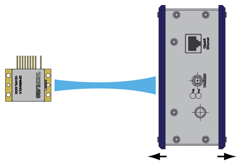
Figure 817A This schematic shows the setup for beam profile measurements of a QF4650HHLH quantum cascade laser. A pyroelectric camera was translated along the beam propagation direction to obtain beam profiles at various distances from the QCL.
The apparatus we used to determine M2 is shown schematically in Figure 817A. To ensure that our results were rigorous, all data acquisition and analysis were consistent with the ISO 11146 standard.
The QF4650HHLH Quantum Cascade Laser used for this measurement emitted CW laser light with a center wavelength of 4.595 µm. The laser was temperature stabilized at 25 °C using the HHL’s internal thermistor and TEC. The output beam was collimated by a 390037-E lens placed immediately in front of the laser facet within the HHL. This lens was selected because of its large NA of 0.85 (which helped maximize collection of the emitted light) and because of its AR coating (Ravg < 0.6% per surface from 3 µm to 5 µm). The laser had an output power of about 20 mW during this measurement.
A pyroelectric camera (Spiricon Pyrocam III-HR) with 80 µm square pixels was scanned along the beam propagation direction, and the beam width was measured along the parallel and perpendicular directions. The beam profiler has several different methods for determining the beam width from the measured beam profile. We found that the best results were obtained by using the 90-10 knife-edge method, where an algorithm is used to simulate scanning a knife-edge across the beam and finding the points of 10% and 90% power. These widths are then converted to the equivalent widths using the second-order moment (D4σ) definition so that they can be used in determining M2 while following the ISO standard. Hyperbolas were fit to the beam width to extract M2 for each beam axis. The camera's internal chopper was triggered at 50 Hz since the pyroelectric effect is sensitive to changes in temperature rather than absolute temperature differences.
Data Analysis
Figure 817B shows the second-order moment (D4σ) beam widths for the parallel and perpendicular directions as a function of distance from the laser. Along the parallel direction, we obtained a minimum beam width of 1.5 mm, while along the perpendicular direction, we obtained a minimum beam width of 1.4 mm. The spatial profiles were observed along the beam path using the pyroelectric camera, with two examples shown in Figures 817D and 817E.
The divergence of the beam can be described by a hyperbola, as written in Equation 1:
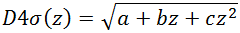 |
(Eq. 1) |
In order to obtain the hyperbola coefficients a, b, and c for the parallel and perpendicular directions, we fit the discrete beam width measurements along each direction to hyperbolas, as shown in the graph in Figure 817B These coefficients were substituted into Equation 2 (taking λ = 4.595 µm) to yield M2.
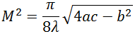 |
(Eq. 2) |
The hyperbola coefficients and M2 values derived by this method are listed in Table 817C.
| Table 817C Hyperbola Coefficients and M2 Values | ||
|---|---|---|
| Value | Parallel | Perpendicular |
| a | 3.82 ± 0.03 mm2 | 5.71 ± 0.04 mm2 |
| b | -0.0110 ± 0.0001 mm | -0.0169 ± 0.0001 mm |
| c | (1.764 ± 0.008) × 10-5 | (1.856 ± 0.009) × 10-5 |
| M2 | 1.04 ± 0.01 | 1.00 ± 0.2 |
As shown by the graph in Figure 817B, the beam waist of the parallel direction occurred around z = 300 mm, while the beam waist of the perpendicular direction occurred around z = 450 mm. The small astigmatism corresponds closely to what is expected for this laser given the emitter shape and beam divergences.
Click to Enlarge
Figure 817D Beam Profile near Beam Waists, 352 mm from Laser
Click to Enlarge
Figure 817E Beam Profile after Propagation, 1012 mm from Laser

Insights into QCLs and ICLs
Scroll down to read about:
- QCLs and ICLs: Operating Limits and Thermal Rollover
Click here for more insights into lab practices and equipment.
QCLs and ICLs: Operating Limits and Thermal Rollover
Click to Enlarge
Figure 183B This set of L-I curves for a QCL laser illustrates that the mount temperature can affect the peak operating temperature, but that using a temperature controlled mount does not remove the danger of applying a driving current large enough to exceed the rollover point and risk damaging the laser.
Click to Enlarge
Figure 183A This example of an L-I curve for a QCL laser illustrates the typical non-linear slope and rollover region exhibited by QCL and ICL lasers. Operating parameters determine the heat load carried by the lasing region, which influences the peak output power. This laser was installed in a temperature controlled mount set to 25 °C.
The light vs. driving current (L-I) curves measured for quantum and interband cascade Lasers (QCLs and ICLs) include a rollover region, which is enclosed by the red box in Figure 183A.
The rollover region includes the peak output power of the laser, which corresponds to a driving current of just under 500 mA in this example. Applying higher drive currents risks damaging the laser.
Laser Operation
These lasers operate by forcing electrons down a controlled series of energy steps, which are created by the laser's semiconductor layer structure and an applied bias voltage. The driving current supplies the electrons.
An electron must give up some of its energy to drop down to a lower energy level. When an electron descends one of the laser's energy steps, the electron loses energy in the form of a photon. But, the electron can also lose energy by giving it to the semiconductor material as heat, instead of emitting a photon.
Heat Build Up
Lasers are not 100% efficient in forcing electrons to surrender their energy in the form of photons. The electrons that lose their energy as heat cause the temperature of the lasing region to increase.
Conversely, heat in the lasing region can be absorbed by electrons. This boost in energy can scatter electrons away from the path leading down the laser's energy steps. Later, scattered electrons typically lose energy as heat, instead of as photons.
As the temperature of the lasing region increases, more electrons are scattered, and a smaller fraction of them produce light instead of heat. Rising temperatures can also result in changes to the laser's energy levels that make it harder for electrons to emit photons. These processes work together to increase the temperature of the lasing region and to decrease the efficiency with which the laser converts current to laser light.
Operating Limits are Determined by the Heat Load
Ideally, the slope of the L-I curve would be linear above the threshold current, which is around 270 mA in Figure 183A. Instead, the slope decreases as the driving current increases, which is due to the effects from the rising temperature of the lasing region. Rollover occurs when the laser is no longer effective in converting additional current to laser light. Instead, the extra driving creates only heat. When the current is high enough, the strong localized heating of the laser region will cause the laser to fail.
A temperature controlled mount is typically necessary to help manage the temperature of the lasing region. But, since the thermal conductivity of the semiconductor material is not high, heat can still build up in the lasing region. As illustrated in Figure 183B, the mount temperature affects the peak optical output power but does not prevent rollover.
The maximum drive current and the maximum optical output power of QCLs and ICLs depend on the operating conditions, since these determine the heat load of the lasing region.
Date of Last Edit: Dec. 4, 2019
Click to Enlarge
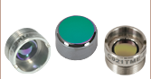
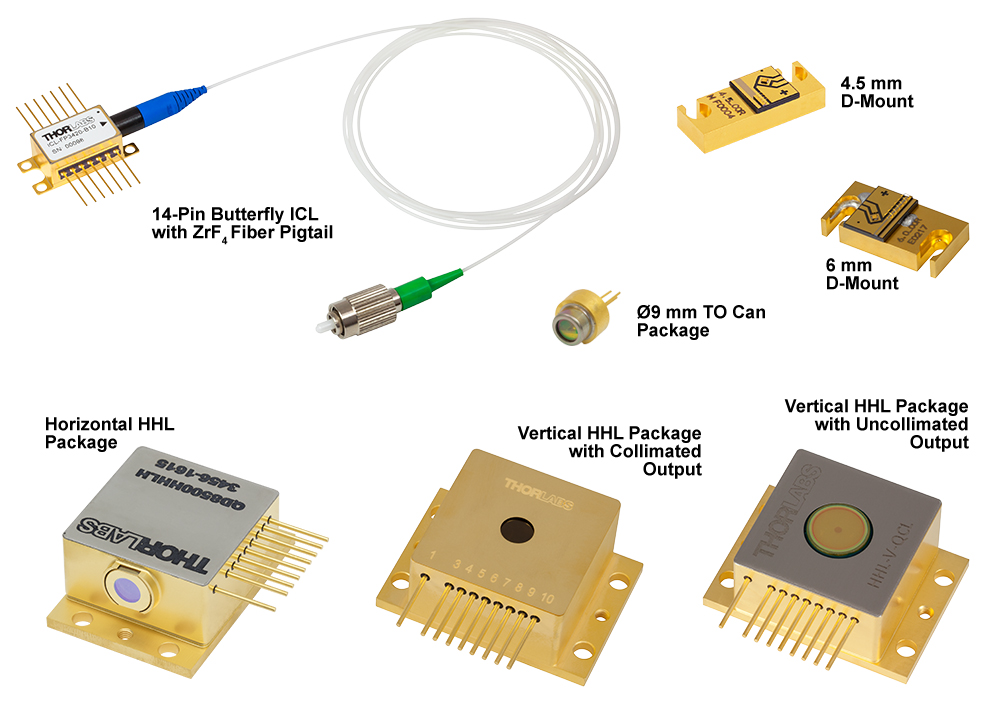
Figure 166B Some of Our Available Packages
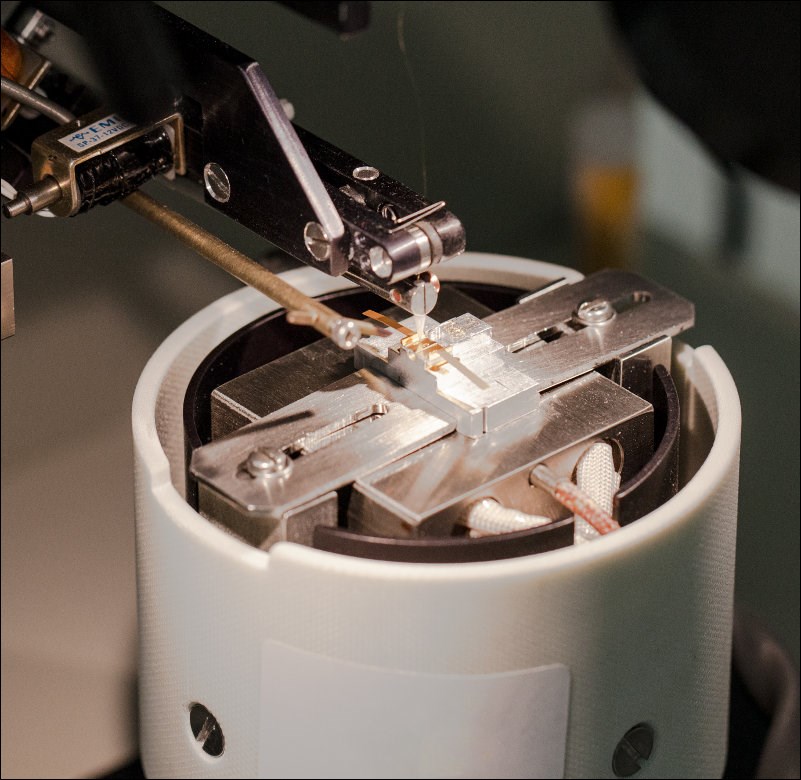
Click for Details
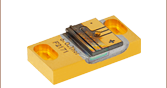
Figure 166A Wire Bonding a Quantum Cascade Laser on a C-Mount
Custom & OEM Quantum Cascade and Interband Cascade Lasers
At our semiconductor manufacturing facility in Jessup, Maryland, we build fully packaged mid-IR lasers and gain chips. Our engineering team performs in-house epitaxial growth, wafer fabrication, and laser packaging. We maintain chip inventory from 3 µm to 12 µm, and our vertically integrated facilities are well equipped to fulfill unique requests.
High-Power Fabry-Perot QCLs
For Fabry-Perot lasers, we can reach multi-watt output power on certain custom orders. The available power depends upon several factors, including the wavelength and the desired package.
DFB QCLs at Custom Wavelengths
For distributed feedback (DFB) lasers, we can deliver a wide range of center wavelengths with user-defined wavelength precision. Our semiconductor specialists will take your application requirements into account when discussing the options with you.
Figures 166A through 166E illustrate some of our custom capabilities. Please visit our semiconductor manufacturing capabilities presentation to learn more.
![]()
Click to Enlarge
Figure 166C Available Wavelengths for Custom QCLs and ICLs
Click to Enlarge
Figure 166D Maximum Output Power of Custom Fabry-Perot QCLs
Click to Enlarge
Figure 166E Electroluminescence Spectra of Available Gain Chip Material
| Posted Comments: | |
三星 陽平
(posted 2023-06-12 10:36:17.56) ソーラボジャパン株式会社 ご担当者様
長岡技術科学大学 応用波動光学研究室の三星陽平と申します。
本日は先日、弊社で購入させていただいたファブリペロー型量子カスケードレーザー(QCL)、中心波長3.85μm、水平出力HHLパッケージ | CAS-548566-D5F2D3 において質問があります。
本レーザーを4月の下旬に購入したのですが、当時は本レーザーに対応したマウントが発売されていないとのことで5月の下旬にリリースするかもしれないとお聞きしました。
現在、本レーザーに対応したマウントは発売されていますでしょうか。
ご返信いただければ幸いです。
-----------------------------------------------------------------------------
三星 陽平
長岡技術科学大学 工学部
応用波動光学研究室
電気電子情報工学科 4年
E-mail : s223145@stn.nagaokaut.ac.jp ksosnowski
(posted 2023-06-13 01:21:26.0) Hello, thanks for reaching out to Thorlabs. Your local tech support team is reaching out to discuss this application further. |
| The rows shaded green below denote single-frequency lasers. |
| Item # | Wavelength | Output Power | Operating Current | Operating Voltage | Beam Divergence | Laser Mode | Package | |
|---|---|---|---|---|---|---|---|---|
| Parallel | Perpendicular | |||||||
| L375P70MLD | 375 nm | 70 mW | 110 mA | 5.4 V | 9° | 22.5° | Single Transverse Mode | Ø5.6 mm |
| L404P400M | 404 nm | 400 mW | 370 mA | 4.9 V | 13° (1/e2) | 42° (1/e2) | Multimode | Ø5.6 mm |
| LP405-SF10 | 405 nm | 10 mW | 50 mA | 5.0 V | - | - | Single Transverse Mode | Ø5.6 mm, SM Pigtail |
| L405P20 | 405 nm | 20 mW | 38 mA | 4.8 V | 8.5° | 19° | Single Transverse Mode | Ø5.6 mm |
| LP405C1 | 405 nm | 30 mW | 75 mA | 4.3 V | 1.4 mrad | 1.4 mrad | Single Transverse Mode | Ø3.8 mm, SM Pigtail with Collimator |
| L405G2 | 405 nm | 35 mW | 50 mA | 4.9 V | 10° | 21° | Single Transverse Mode | Ø3.8 mm |
| DL5146-101S | 405 nm | 40 mW | 70 mA | 5.2 V | 8° | 19° | Single Transverse Mode | Ø5.6 mm |
| L405A1 | 405 nm | 175 mW (Min) | 150 mA | 5.0 V | 9° | 20° | Single Transverse Mode | Ø5.6 mm |
| LP405-MF300 | 405 nm | 300 mW | 350 mA | 4.5 V | - | - | Multimode | Ø5.6 mm, MM Pigtail |
| L405G1 | 405 nm | 1000 mW | 900 mA | 5.0 V | 13° | 45° | Multimode | Ø9 mm |
| LP450-SF25 | 450 nm | 25 mW | 75 mA | 5.0 V | - | - | Single Transverse Mode | Ø5.6 mm, SM Pigtail |
| L450G3 | 450 nm | 100 mW (Min) | 80 mA | 5.2 V | 8.4° | 21.5° | Single Transverse Mode | Ø3.8 mm |
| L450G2 | 450 nm | 100 mW (Min) | 80 mA | 5.0 V | 8.4° | 21.5° | Single Transverse Mode | Ø5.6 mm |
| L450P1600MM | 450 nm | 1600 mW | 1200 mA | 4.8 V | 7° | 19 - 27° | Multimode | Ø5.6 mm |
| L473P100 | 473 nm | 100 mW | 120 mA | 5.7 V | 10 | 24 | Single Transverse Mode | Ø5.6 mm |
| LP488-SF20 | 488 nm | 20 mW | 70 mA | 6.0 V | - | - | Single Transverse Mode | Ø5.6 mm, SM Pigtail |
| LP488-SF20G | 488 nm | 20 mW | 80 mA | 5.5 V | - | - | Single Transverse Mode | Ø5.6 mm, SM Pigtail |
| L488P60 | 488 nm | 60 mW | 75 mA | 6.8 V | 7° | 23° | Single Transverse Mode | Ø5.6 mm |
| LP505-SA15 | 505 nm | 15 mW | 80 mA | 7.0 V | - | - | Single Transverse Mode | Ø5.6 mm, SM Pigtail |
| LP505-SF15 | 505 nm | 15 mW | 80 mA | 7.0 V | - | - | Single Transverse Mode | Ø5.6 mm, SM Pigtail |
| L505P30 | 505 nm | 30 mW | 80 mA | 6.7 V | 8° | 23° | Single Transverse Mode | Ø5.6 mm |
| LP514-SA25 | 514 nm | 25 mW | 140 mA | 5.9 V | - | - | Single Transverse Mode | Ø5.6 mm, SM Pigtail |
| LP514-SF25 | 514 nm | 25 mW | 140 mA | 5.9 V | - | - | Single Transverse Mode | Ø5.6 mm, SM Pigtail |
| L514A2 | 514 nm | 45 mW (Min) | 115 mA | 5.7 V | 8° | 22° | Single Transverse Mode | Ø5.6 mm |
| LP515-SF3 | 515 nm | 3 mW | 50 mA | 5.3 V | - | - | Single Transverse Mode | Ø5.6 mm, SM Pigtail |
| L515A1 | 515 nm | 10 mW | 50 mA | 5.4 V | 6.5° | 21° | Single Transverse Mode | Ø5.6 mm |
| LP520-SF15A | 520 nm | 15 mW | 100 mA | 7.0 V | - | - | Single Transverse Mode | Ø5.6 mm, SM Pigtail |
| L520A1 | 520 nm | 30 mW (Min) | 80 mA | 5.5 V | 8° | 22° | Single Transverse Mode | Ø5.6 mm |
| LP520-SF40 | 520 nm | 40 mW | 190 mA | 6.0 V | - | - | Single Transverse Mode | Ø5.6 mm, SM Pigtail |
| PL520 | 520 nm | 50 mW | 250 mA | 7.0 V | 7° | 22° | Single Transverse Mode | Ø3.8 mm |
| L520P50 | 520 nm | 45 mW | 150 mA | 7.0 V | 7° | 22° | Single Transverse Mode | Ø5.6 mm |
| L520A2 | 520 nm | 110 mW (Min) | 225 mA | 5.9 V | 8° | 22° | Single Transverse Mode | Ø5.6 mm |
| DJ532-10 | 532 nm | 10 mW | 220 mA | 1.9 V | 0.69° | 0.69° | Single Transverse Mode | Ø9.5 mm (non-standard) |
| DJ532-40 | 532 nm | 40 mW | 330 mA | 1.9 V | 0.69° | 0.69° | Single Transverse Mode | Ø9.5 mm (non-standard) |
| LP633-SF50 | 633 nm | 50 mW | 170 mA | 2.6 V | - | - | Single Transverse Mode | Ø5.6 mm, SM Pigtail |
| HL63163DG | 633 nm | 100 mW | 170 mA | 2.6 V | 8.5° | 18° | Single Transverse Mode | Ø5.6 mm |
| LPS-635-FC | 635 nm | 2.5 mW | 70 mA | 2.2 V | - | - | Single Transverse Mode | Ø9 mm, SM Pigtail |
| LPS-PM635-FC | 635 nm | 2.5 mW | 60 mA | 2.2 V | - | - | Single Transverse Mode | Ø9 mm, PM Pigtail |
| L635P5 | 635 nm | 5 mW | 30 mA | <2.7 V | 8° | 32° | Single Transverse Mode | Ø5.6 mm |
| HL6312G | 635 nm | 5 mW | 50 mA | <2.7 V | 8° | 31° | Single Transverse Mode | Ø9 mm |
| LPM-635-SMA | 635 nm | 8 mW | 50 mA | 2.2 V | - | - | Multimode | Ø9 mm, MM Pigtail |
| LP635-SF8 | 635 nm | 8 mW | 60 mA | 2.3 V | - | - | Single Transverse Mode | Ø5.6 mm, SM Pigtail |
| HL6320G | 635 nm | 10 mW | 60 mA | 2.2 V | 8° | 31° | Single Transverse Mode | Ø9 mm |
| HL6322G | 635 nm | 15 mW | 75 mA | 2.4 V | 8° | 30° | Single Transverse Mode | Ø9 mm |
| L637P5 | 637 nm | 5 mW | 20 mA | <2.4 V | 8° | 34° | Single Transverse Mode | Ø5.6 mm |
| LP637-SF50 | 637 nm | 50 mW | 140 mA | 2.6 V | - | - | Single Transverse Mode | Ø5.6 mm, SM Pigtail |
| LP637-SF70 | 637 nm | 70 mW | 220 mA | 2.7 V | - | - | Single Transverse Mode | Ø5.6 mm, SM Pigtail |
| HL63142DG | 637 nm | 100 mW | 140 mA | 2.7 V | 8° | 18° | Single Transverse Mode | Ø5.6 mm |
| HL63133DG | 637 nm | 170 mW | 250 mA | 2.8 V | 9° | 17° | Single Transverse Mode | Ø5.6 mm |
| HL6388MG | 637 nm | 250 mW | 340 mA | 2.3 V | 10° | 40° | Multimode | Ø5.6 mm |
| L637G1 | 637 nm | 1200 mW | 1100 mA | 2.5 V | 10° | 32° | Multimode | Ø9 mm (non-standard) |
| L638P040 | 638 nm | 40 mW | 92 mA | 2.4 V | 10° | 21° | Single Transverse Mode | Ø5.6 mm |
| L638P150 | 638 nm | 150 mW | 230 mA | 2.7 V | 9 | 18 | Single Transverse Mode | Ø3.8 mm |
| L638P200 | 638 nm | 200 mW | 280 mA | 2.9 V | 8 | 14 | Single Transverse Mode | Ø5.6 mm |
| L638P700M | 638 nm | 700 mW | 820 mA | 2.2 V | 9° | 35° | Multimode | Ø5.6 mm |
| HL6358MG | 639 nm | 10 mW | 40 mA | 2.4 V | 8° | 21° | Single Transverse Mode | Ø5.6 mm |
| HL6323MG | 639 nm | 30 mW | 100 mA | 2.5 V | 8.5° | 30° | Single Transverse Mode | Ø5.6 mm |
| HL6362MG | 640 nm | 40 mW | 90 mA | 2.5 V | 10° | 21° | Single Transverse Mode | Ø5.6 mm |
| LP642-SF20 | 642 nm | 20 mW | 90 mA | 2.5 V | - | - | Single Transverse Mode | Ø5.6 mm, SM Pigtail |
| LP642-PF20 | 642 nm | 20 mW | 110 mA | 2.5 V | - | - | Single Transverse Mode | Ø5.6 mm, PM Pigtail |
| HL6364DG | 642 nm | 60 mW | 120 mA | 2.5 V | 10° | 21° | Single Transverse Mode | Ø5.6 mm |
| HL6366DG | 642 nm | 80 mW | 150 mA | 2.5 V | 10° | 21° | Single Transverse Mode | Ø5.6 mm |
| HL6385DG | 642 nm | 150 mW | 250 mA | 2.6 V | 9° | 17° | Single Transverse Mode | Ø5.6 mm |
| L650P007 | 650 nm | 7 mW | 28 mA | 2.2 V | 9° | 28° | Single Transverse Mode | Ø5.6 mm |
| LPS-660-FC | 658 nm | 7.5 mW | 65 mA | 2.6 V | - | - | Single Transverse Mode | Ø5.6 mm, SM Pigtail |
| LP660-SF20 | 658 nm | 20 mW | 80 mA | 2.6 V | - | - | Single Transverse Mode | Ø5.6 mm, SM Pigtail |
| LPM-660-SMA | 658 nm | 22.5 mW | 65 mA | 2.6 V | - | - | Multimode | Ø5.6 mm, MM Pigtail |
| HL6501MG | 658 nm | 30 mW | 75 mA | 2.6 V | 8.5° | 22° | Single Transverse Mode | Ø5.6 mm |
| L658P040 | 658 nm | 40 mW | 75 mA | 2.2 V | 10° | 20° | Single Transverse Mode | Ø5.6 mm |
| LP660-SF40 | 658 nm | 40 mW | 135 mA | 2.5 V | - | - | Single Transverse Mode | Ø5.6 mm, SM Pigtail |
| LP660-SF60 | 658 nm | 60 mW | 210 mA | 2.4 V | - | - | Single Transverse Mode | Ø5.6 mm, SM Pigtail |
| HL6544FM | 660 nm | 50 mW | 115 mA | 2.3 V | 10° | 17° | Single Transverse Mode | Ø5.6 mm |
| LP660-SF50 | 660 nm | 50 mW | 140 mA | 2.3 V | - | - | Single Transverse Mode | Ø5.6 mm, SM Pigtail |
| HL6545MG | 660 nm | 120 mW | 170 mA | 2.45 V | 10° | 17° | Single Transverse Mode | Ø5.6 mm |
| L660P120 | 660 nm | 120 mW | 175 mA | 2.5 V | 10° | 17° | Single Transverse Mode | Ø5.6 mm |
| L670VH1 | 670 nm | 1 mW | 2.5 mA | 2.6 V | 10° | 10° | Single Transverse Mode | TO-46 |
| LPS-675-FC | 670 nm | 2.5 mW | 55 mA | 2.2 V | - | - | Single Transverse Mode | Ø9 mm, SM Pigtail |
| HL6748MG | 670 nm | 10 mW | 30 mA | 2.2 V | 8° | 25° | Single Transverse Mode | Ø5.6 mm |
| HL6714G | 670 nm | 10 mW | 55 mA | <2.7 V | 8° | 22° | Single Transverse Mode | Ø9 mm |
| HL6756MG | 670 nm | 15 mW | 35 mA | 2.3 V | 8° | 24° | Single Transverse Mode | Ø5.6 mm |
| LP685-SF15 | 685 nm | 15 mW | 55 mA | 2.1 V | - | - | Single Transverse Mode | Ø5.6 mm, SM Pigtail |
| HL6750MG | 685 nm | 50 mW | 70 mA | 2.3 V | 9° | 21° | Single Transverse Mode | Ø5.6 mm |
| HL6738MG | 690 nm | 30 mW | 85 mA | 2.5 V | 8.5° | 19° | Single Transverse Mode | Ø5.6 mm |
| LP705-SF15 | 705 nm | 15 mW | 55 mA | 2.3 V | - | - | Single Transverse Mode | Ø5.6 mm, SM Pigtail |
| HL7001MG | 705 nm | 40 mW | 75 mA | 2.5 V | 9° | 18° | Single Transverse Mode | Ø5.6 mm |
| LP730-SF15 | 730 nm | 15 mW | 70 mA | 2.5 V | - | - | Single Transverse Mode | Ø5.6 mm, SM Pigtail |
| HL7302MG | 730 nm | 40 mW | 75 mA | 2.5 V | 9° | 18° | Single Transverse Mode | Ø5.6 mm |
| L760VH1 | 760 nm | 0.5 mW | 3 mA (Max) | 2.2 V | 12° | 12° | Single Frequency | TO-46 |
| DBR760PN | 761 nm | 9 mW | 125 mA | 2.0 V | - | - | Single Frequency | Butterfly, PM Pigtail |
| L763VH1 | 763 nm | 0.5 mW | 3 mA (Max) | 2.0 V | 10° | 10° | Single Frequency | TO-46 |
| DBR767PN | 767 nm | 23 mW | 220 mA | 1.87 V | - | - | Single Frequency | Butterfly, PM Pigtail |
| DBR770PN | 770 nm | 35 mW | 220 mA | 1.92 V | - | - | Single Frequency | Butterfly, PM Pigtail |
| L780P010 | 780 nm | 10 mW | 24 mA | 1.8 V | 8° | 30° | Single Transverse Mode | Ø5.6 mm |
| DBR780PN | 780 nm | 45 mW | 250 mA | 1.9 V | - | - | Single Frequency | Butterfly, PM Pigtail |
| ULN780PC | 780 nm | 70 mW | 600 mA | 3.0 V | - | - | Single Frequency | Butterfly, PM Pigtail |
| L785P5 | 785 nm | 5 mW | 28 mA | 1.9 V | 10° | 29° | Single Transverse Mode | Ø5.6 mm |
| LPS-PM785-FC | 785 nm | 6.5 mW | 60 mA | - | - | - | Single Transverse Mode | Ø5.6 mm, PM Pigtail |
| LPS-785-FC | 785 nm | 10 mW | 65 mA | 1.85 V | - | - | Single Transverse Mode | Ø5.6 mm, SM Pigtail |
| LP785-SF20 | 785 nm | 20 mW | 85 mA | 1.9 V | - | - | Single Transverse Mode | Ø5.6 mm, SM Pigtail |
| DBR785S | 785 nm | 25 mW | 230 mA | 2.0 V | - | - | Single Frequency | Butterfly, SM Pigtail |
| DBR785P | 785 nm | 25 mW | 230 mA | 2.0 V | - | - | Single Frequency | Butterfly, PM Pigtail |
| L785P25 | 785 nm | 25 mW | 45 mA | 1.9 V | 8° | 30° | Single Transverse Mode | Ø5.6 mm |
| FPV785S | 785 nm | 50 mW | 410 mA | 2.2 V | - | - | Single Frequency | Butterfly, SM Pigtail |
| FPV785P | 785 nm | 50 mW | 410 mA | 2.1 V | - | - | Single Frequency | Butterfly, PM Pigtail |
| LP785-SAV50 | 785 nm | 50 mW | 500 mA | 2.2 V | - | - | Single Frequency | Ø9 mm, SM Pigtail |
| L785P090 | 785 nm | 90 mW | 125 mA | 2.0 V | 10° | 17° | Single Transverse Mode | Ø5.6 mm |
| LP785-SF100 | 785 nm | 100 mW | 300 mA | 2.0 V | - | - | Single Transverse Mode | Ø9 mm, SM Pigtail |
| FPL785P | 785 nm | 200 mW | 500 mA | 2.1 V | - | - | Single Transverse Mode | Butterfly, PM Pigtail |
| FPL785S-250 | 785 nm | 250 mW (Min) | 500 mA | 2.0 V | - | - | Single Transverse Mode | Butterfly, SM Pigtail |
| LD785-SEV300 | 785 nm | 300 mW | 500 mA (Max) | 2.0 V | 8° | 16° | Single Frequency | Ø9 mm |
| LD785-SH300 | 785 nm | 300 mW | 400 mA | 2.0 V | 7° | 18° | Single Transverse Mode | Ø9 mm |
| FPL785C | 785 nm | 300 mW | 400 mA | 2.0 V | 7° | 18° | Single Transverse Mode | 3 mm x 5 mm Submount |
| LD785-SE400 | 785 nm | 400 mW | 550 mA | 2.0 V | 7° | 16° | Single Transverse Mode | Ø9 mm |
| FPV785M | 785 nm | 600 mW | 1100 mA | 1.9 V | - | - | Multimode | Butterfly, MM Pigtail |
| L795VH1 | 795 nm | 0.25 mW | 1.2 mA | 1.8 V | 20° | 12° | Single Frequency | TO-46 |
| DBR795PN | 795 nm | 40 mW | 230 mA | 2.0 V | - | - | Single Frequency | Butterfly, PM Pigtail |
| ULN795PC | 795 nm | 100 mW | 700 mA | 3.0 V | - | - | Single Frequency | Butterfly, PM Pigtail |
| DBR808PN | 808 nm | 42 mW | 250 mA | 2 V | - | - | Single Frequency | Butterfly, PM Pigtail |
| LP808-SA60 | 808 nm | 60 mW | 150 mA | 1.9 V | - | - | Single Transverse Mode | Ø9 mm, SM Pigtail |
| M9-808-0150 | 808 nm | 150 mW | 180 mA | 1.9 V | 8° | 17° | Single Transverse Mode | Ø9 mm |
| L808P200 | 808 nm | 200 mW | 260 mA | 2 V | 10° | 30° | Multimode | Ø5.6 mm |
| FPL808P | 808 nm | 200 mW | 600 mA | 2.1 V | - | - | Single Transverse Mode | Butterfly, PM Pigtail |
| FPL808S | 808 nm | 200 mW | 750 mA | 2.3 V | - | - | Single Transverse Mode | Butterfly, SM Pigtail |
| L808H1 | 808 nm | 300 mW | 400 mA | 2.1 V | 14° | 6° | Single Transverse Mode | Ø9 mm |
| LD808-SE500 | 808 nm | 500 mW | 750 mA | 2.2 V | 7° | 14° | Single Transverse Mode | Ø9 mm |
| LD808-SEV500 | 808 nm | 500 mW | 800 mA (Max) | 2.2 V | 8° | 14° | Single Frequency | Ø9 mm |
| L808P500MM | 808 nm | 500 mW | 650 mA | 1.8 V | 12° | 30° | Multimode | Ø5.6 mm |
| L808P1000MM | 808 nm | 1000 mW | 1100 mA | 2 V | 9° | 30° | Multimode | Ø9 mm |
| DBR816PN | 816 nm | 45 mW | 250 mA | 1.95 V | - | - | Single Frequency | Butterfly, PM Pigtail |
| LP820-SF80 | 820 nm | 80 mW | 230 mA | 2.3 V | - | - | Single Transverse Mode | Ø5.6 mm, SM Pigtail |
| L820P100 | 820 nm | 100 mW | 145 mA | 2.1 V | 9° | 17° | Single Transverse Mode | Ø5.6 mm |
| L820P200 | 820 nm | 200 mW | 250 mA | 2.4 V | 9° | 17° | Single Transverse Mode | Ø5.6 mm |
| DBR828PN | 828 nm | 24 mW | 250 mA | 2.0 V | - | - | Single Frequency | Butterfly, PM Pigtail |
| LPS-830-FC | 830 nm | 10 mW | 120 mA | - | - | - | Single Transverse Mode | Ø5.6 mm, SM Pigtail |
| LPS-PM830-FC | 830 nm | 10 mW | 50 mA | 2.0 V | - | - | Single Transverse Mode | Ø5.6 mm, PM Pigtail |
| LP830-SF30 | 830 nm | 30 mW | 115 mA | 1.9 V | - | - | Single Transverse Mode | Ø9 mm, SM Pigtail |
| HL8338MG | 830 nm | 50 mW | 75 mA | 1.9 V | 9° | 22° | Single Transverse Mode | Ø5.6 mm |
| L830H1 | 830 nm | 250 mW | 3 A (Max) | 2 V | 8° | 10° | Single Transverse Mode | Ø9 mm |
| FPL830P | 830 nm | 300 mW | 900 mA | 2.22 V | - | - | Single Transverse Mode | Butterfly, PM Pigtail |
| FPL830S | 830 nm | 350 mW | 900 mA | 2.5 V | - | - | Single Transverse Mode | Butterfly, SM Pigtail |
| LD830-SE650 | 830 nm | 650 mW | 900 mA | 2.3 V | 7° | 13° | Single Transverse Mode | Ø9 mm |
| LD830-MA1W | 830 nm | 1 W | 2 A | 2.1 V | 7° | 24° | Multimode | Ø9 mm |
| LD830-ME2W | 830 nm | 2 W | 3 A (Max) | 2.0 V | 8° | 21° | Multimode | Ø9 mm |
| L840P200 | 840 nm | 200 mW | 255 mA | 2.4 V | 9 | 17 | Single Transverse Mode | Ø5.6 mm |
| L850VH1 | 850 nm | 1 mW | 6 mA (Max) | 2 V | 12° | 12° | Single Frequency | TO-46 |
| L850P010 | 850 nm | 10 mW | 50 mA | 2 V | 10° | 30° | Single Transverse Mode | Ø5.6 mm |
| L850P030 | 850 nm | 30 mW | 65 mA | 2 V | 8.5° | 30° | Single Transverse Mode | Ø5.6 mm |
| FPV852S | 852 nm | 20 mW | 400 mA | 2.2 V | - | - | Single Frequency | Butterfly, SM Pigtail |
| FPV852P | 852 nm | 20 mW | 400 mA | 2.2 V | - | - | Single Frequency | Butterfly, PM Pigtail |
| DBR852PN | 852 nm | 24 mW | 300 mA | 2.0 V | - | - | Single Frequency | Butterfly, PM Pigtail |
| LP852-SF30 | 852 nm | 30 mW | 115 mA | 1.9 V | - | - | Single Transverse Mode | Ø9 mm, SM Pigtail |
| L852P50 | 852 nm | 50 mW | 75 mA | 1.9 V | 9° | 22° | Single Transverse Mode | Ø5.6 mm |
| LP852-SF60 | 852 nm | 60 mW | 150 mA | 2.0 V | - | - | Single Transverse Mode | Ø9 mm, SM Pigtail |
| L852P100 | 852 nm | 100 mW | 120 mA | 1.9 V | 8° | 28° | Single Transverse Mode | Ø9 mm |
| ULN852PC | 852 nm | 100 mW | 700 mA | 3.0 V | - | - | Single Frequency | Butterfly, PM Pigtail |
| L852P150 | 852 nm | 150 mW | 170 mA | 1.9 V | 8° | 18° | Single Transverse Mode | Ø9 mm |
| L852SEV1 | 852 nm | 270 mW | 400 mA (Max) | 2.0 V | 9° | 12° | Single Frequency | Ø9 mm |
| L852H1 | 852 nm | 300 mW | 415 mA (Max) | 2 V | 7° | 15° | Single Transverse Mode | Ø9 mm |
| FPL852P | 852 nm | 300 mW | 900 mA | 2.35 V | - | - | Single Transverse Mode | Butterfly, PM Pigtail |
| FPL852S | 852 nm | 350 mW | 900 mA | 2.5 V | - | - | Single Transverse Mode | Butterfly, SM Pigtail |
| LD852-SE600 | 852 nm | 600 mW | 950 mA | 2.3 V | 7° (1/e2) | 13° (1/e2) | Single Transverse Mode | Ø9 mm |
| LD852-SEV600 | 852 nm | 600 mW | 1050 mA (Max) | 2.2 V | 8° | 13° (1/e2) | Single Frequency | Ø9 mm |
| LP880-SF3 | 880 nm | 3 mW | 25 mA | 2.2 V | - | - | Single Transverse Mode | Ø5.6 mm, SM Pigtail |
| L880P010 | 880 nm | 10 mW | 30 mA | 2.0 V | 12° | 37° | Single Transverse Mode | Ø5.6 mm |
| L895VH1 | 895 nm | 0.2 mW | 1.4 mA | 1.6 V | 20° | 13° | Single Frequency | TO-46 |
| DBR895PN | 895 nm | 12 mW | 300 mA | 2 V | - | - | Single Frequency | Butterfly, PM Pigtail |
| LP904-SF3 | 904 nm | 3 mW | 30 mA | 1.5 V | - | - | Single Transverse Mode | Ø5.6 mm, SM Pigtail |
| L904P010 | 904 nm | 10 mW | 50 mA | 2.0 V | 10° | 30° | Single Transverse Mode | Ø5.6 mm |
| LP915-SF40 | 915 nm | 40 mW | 130 mA | 1.5 V | - | - | Single Transverse Mode | Ø9 mm, SM Pigtail |
| DBR935PN | 935 nm | 13 mW | 300 mA | 1.75 V | - | - | Single Frequency | Butterfly, PM Pigtail |
| LP940-SF30 | 940 nm | 30 mW | 90 mA | 1.5 V | - | - | Single Transverse Mode | Ø9 mm, SM Pigtail |
| M9-940-0200 | 940 nm | 200 mW | 270 mA | 1.9 V | 8° | 28° | Single Transverse Mode | Ø9 mm |
| L960H1 | 960 nm | 250 mW | 400 mA | 2.1 V | 11° | 12° | Single Transverse Mode | Ø9 mm |
| FPV976S | 976 nm | 30 mW | 400 mA (Max) | 2.2 V | - | - | Single Frequency | Butterfly, SM Pigtail |
| FPV976P | 976 nm | 30 mW | 400 mA (Max) | 2.2 V | - | - | Single Frequency | Butterfly, PM Pigtail |
| DBR976PN | 976 nm | 33 mW | 450 mA | 2.0 V | - | - | Single Frequency | Butterfly, PM Pigtail |
| L976SEV1 | 976 nm | 270 mW | 400 mA (Max) | 2.0 V | 9° | 12° | Single Frequency | Ø9 mm |
| BL976-SAG3 | 976 nm | 300 mW | 470 mA | 2.0 V | - | - | Single Transverse Mode | Butterfly, SM Pigtail |
| BL976-PAG500 | 976 nm | 500 mW | 830 mA | 2.0 V | - | - | Single Transverse Mode | Butterfly, PM Pigtail |
| BL976-PAG700 | 976 nm | 700 mW | 1090 mA | 2.0 V | - | - | Single Transverse Mode | Butterfly, PM Pigtail |
| BL976-PAG900 | 976 nm | 900 mW | 1480 mA | 2.5 V | - | - | Single Transverse Mode | Butterfly, PM Pigtail |
| L980P010 | 980 nm | 10 mW | 25 mA | 2 V | 10° | 30° | Single Transverse Mode | Ø5.6 mm |
| LP980-SF15 | 980 nm | 15 mW | 70 mA | 1.5 V | - | - | Single Transverse Mode | Ø5.6 mm, SM Pigtail |
| L980P030 | 980 nm | 30 mW | 50 mA | 1.5 V | 10° | 35° | Single Transverse Mode | Ø5.6 mm |
| L980P100A | 980 nm | 100 mW | 150 mA | 1.6 V | 6° | 32° | Multimode | Ø5.6 mm |
| LP980-SA60 | 980 nm | 60 mW | 230 mA | 2.0 V | - | - | Single Transverse Mode | Ø9 mm, SM Pigtail |
| L980H1 | 980 nm | 200 mW | 300 mA (Max) | 2.0 V | 8° | 13° | Single Transverse Mode | Ø9 mm |
| L980P200 | 980 nm | 200 mW | 300 mA | 1.5 V | 6° | 30° | Multimode | Ø5.6 mm |
| DBR1060SN | 1060 nm | 130 mW | 650 mA | 2.0 V | - | - | Single Frequency | Butterfly, SM Pigtail |
| DBR1060PN | 1060 nm | 130 mW | 650 mA | 1.8 V | - | - | Single Frequency | Butterfly, PM Pigtail |
| DBR1064S | 1064 nm | 40 mW | 150 mA | 2.0 V | - | - | Single Frequency | Butterfly, SM Pigtail |
| DBR1064P | 1064 nm | 40 mW | 150 mA | 2.0 V | - | - | Single Frequency | Butterfly, PM Pigtail |
| DBR1064PN | 1064 nm | 110 mW | 550 mA | 2.0 V | - | - | Single Frequency | Butterfly, PM Pigtail |
| LPS-1060-FC | 1064 nm | 50 mW | 220 mA | 1.4 V | - | - | Single Transverse Mode | Ø9 mm, SM Pigtail |
| M9-A64-0200 | 1064 nm | 200 mW | 280 mA | 1.7 V | 8° | 28° | Single Transverse Mode | Ø9 mm |
| L1064H1 | 1064 nm | 300 mW | 700 mA | 1.92 V | 7.6° | 13.5° | Single Transverse Mode | Ø9 mm |
| L1064H2 | 1064 nm | 450 mW | 1100 mA | 1.92 V | 7.6° | 13.5° | Single Transverse Mode | Ø9 mm |
| DBR1083PN | 1083 nm | 100 mW | 500 mA | 1.75 V | - | - | Single Frequency | Butterfly, PM Pigtail |
| L1270P5DFB | 1270 nm | 5 mW | 15 mA | 1.1 V | 7° | 9° | Single Frequency | Ø5.6 mm |
| LP1270-SAD2 | 1270 nm | 15 mW | 100 mA (Max) | 1.3 V | - | - | Single Frequency | Ø5.6 mm, SM Pigtail |
| LP1270-PAD2 | 1270 nm | 15 mW | 100 mA (Max) | 1.3 V | - | - | Single Frequency | Ø5.6 mm, PM Pigtail |
| L1290P5DFB | 1290 nm | 5 mW | 16 mA | 1.0 V | 7° | 9° | Single Frequency | Ø5.6 mm |
| LP1290-SAD2 | 1290 nm | 15 mW | 100 mA (Max) | 1.3 V | - | - | Single Frequency | Ø5.6 mm, SM Pigtail |
| LP1290-PAD2 | 1290 nm | 15 mW | 100 mA (Max) | 1.3 V | - | - | Single Frequency | Ø5.6 mm, PM Pigtail |
| LP1310-SAD2 | 1310 nm | 2.0 mW | 40 mA | 1.1 V | - | - | Single Frequency | Ø5.6 mm, SM Pigtail |
| LP1310-PAD2 | 1310 nm | 2.0 mW | 40 mA | 1.0 V | - | - | Single Frequency | Ø5.6 mm, PM Pigtail |
| L1310P5DFB | 1310 nm | 5 mW | 16 mA | 1.0 V | 7° | 9° | Single Frequency | Ø5.6 mm |
| LPSC-1310-FC | 1310 nm | 50 mW | 350 mA | 2 V | - | - | Single Transverse Mode | Ø5.6 mm, SM Pigtail |
| FPL1053S | 1310 nm | 130 mW | 400 mA | 1.7 V | - | - | Single Transverse Mode | Butterfly, SM Pigtail |
| FPL1053P | 1310 nm | 130 mW | 400 mA | 1.7 V | - | - | Single Transverse Mode | Butterfly, PM Pigtail |
| FPL1053T | 1310 nm | 300 mW (Pulsed) | 750 mA | 2 V | 15° | 28° | Single Transverse Mode | Ø5.6 mm |
| FPL1053C | 1310 nm | 300 mW (Pulsed) | 750 mA | 2 V | 15° | 27° | Single Transverse Mode | Chip on Submount |
| L1310G1 | 1310 nm | 2000 mW | 5 A | 1.5 V | 7° | 24° | Multimode | Ø9 mm |
| DFB1320P | 1320 nm | 250 mW (Min) | 1800 mA (Max) | 3.0 V | - | - | Single Frequency | Butterfly, PM Pigtail |
| L1330P5DFB | 1330 nm | 5 mW | 14 mA | 1.0 V | 7° | 9° | Single Frequency | Ø5.6 mm |
| LP1330-SAD2 | 1330 nm | 15 mW | 100 mA (Max) | 1.3 V | - | - | Single Frequency | Ø5.6 mm, SM Pigtail |
| LP1330-PAD2 | 1330 nm | 15 mW | 100 mA (Max) | 1.3 V | - | - | Single Frequency | Ø5.6 mm, PM Pigtail |
| L1370G1 | 1370 nm | 2000 mW | 5 A | 1.4 V | 6° | 22° | Multimode | Ø9 mm |
| BL1425-PAG500 | 1425 nm | 500 mW | 1600 mA | 2.0 V | - | - | Single Transverse Mode | Butterfly, PM Pigtail |
| BL1436-PAG500 | 1436 nm | 500 mW | 1600 mA | 2.0 V | - | - | Single Transverse Mode | Butterfly, PM Pigtail |
| L1450G1 | 1450 nm | 2000 mW | 5 A | 1.4 V | 7° | 22° | Multimode | Ø9 mm |
| BL1456-PAG500 | 1456 nm | 500 mW | 1600 mA | 2.0 V | - | - | Single Transverse Mode | Butterfly, PM Pigtail |
| L1470P5DFB | 1470 nm | 5 mW | 19 mA | 1.0 V | 7° | 9° | Single Frequency | Ø5.6 mm |
| L1480G1 | 1480 nm | 2000 mW | 5 A | 1.6 V | 6° | 20° | Multimode | Ø9 mm |
| L1490P5DFB | 1490 nm | 5 mW | 24 mA | 1.0 V | 7° | 9° | Single Frequency | Ø5.6 mm |
| L1510P5DFB | 1510 nm | 5 mW | 20 mA | 1.0 V | 7° | 9° | Single Frequency | Ø5.6 mm |
| L1530P5DFB | 1530 nm | 5 mW | 21 mA | 1.0 V | 7° | 9° | Single Frequency | Ø5.6 mm |
| LPS-1550-FC | 1550 nm | 1.5 mW | 30 mA | 1.0 V | - | - | Single Transverse Mode | Ø5.6 mm, SM Pigtail |
| LPS-PM1550-FC | 1550 nm | 1.5 mW | 30 mA | 1.1 V | - | - | Single Transverse Mode | Ø5.6 mm, SM Pigtail |
| LP1550-SAD2 | 1550 nm | 2.0 mW | 40 mA | 1.0 V | - | - | Single Frequency | Ø5.6 mm, SM Pigtail |
| LP1550-PAD2 | 1550 nm | 2.0 mW | 40 mA | 1.0 V | - | - | Single Frequency | Ø5.6 mm, PM Pigtail |
| L1550P5DFB | 1550 nm | 5 mW | 20 mA | 1.0 V | 8° | 10° | Single Frequency | Ø5.6 mm |
| ML925B45F | 1550 nm | 5 mW | 30 mA | 1.1 V | 25° | 30° | Single Transverse Mode | Ø5.6 mm |
| SFL1550S | 1550 nm | 40 mW | 300 mA | 1.5 V | - | - | Single Frequency | Butterfly, SM Pigtail |
| SFL1550P | 1550 nm | 40 mW | 300 mA | 1.5 V | - | - | Single Frequency | Butterfly, PM Pigtail |
| LPSC-1550-FC | 1550 nm | 50 mW | 250 mA | 2 V | - | - | Single Transverse Mode | Ø5.6 mm, SM Pigtail |
| FPL1009S | 1550 nm | 100 mW | 400 mA | 1.4 V | - | - | Single Transverse Mode | Butterfly, SM Pigtail |
| FPL1009P | 1550 nm | 100 mW | 400 mA | 1.4 V | - | - | Single Transverse Mode | Butterfly, PM Pigtail |
| ULN15PC | 1550 nm | 140 mW | 650 mA | 3.0 V | - | - | Single Frequency | Extended Butterfly, PM Pigtail |
| ULN15PT | 1550 nm | 140 mW | 650 mA | 3.0 V | - | - | Single Frequency | Extended Butterfly, PM Pigtail |
| FPL1001C | 1550 nm | 150 mW | 400 mA | 1.4 V | 18° | 31° | Single Transverse Mode | Chip on Submount |
| FPL1055T | 1550 nm | 300 mW (Pulsed) | 750 mA | 2 V | 15° | 28° | Single Transverse Mode | Ø5.6 mm |
| FPL1055C | 1550 nm | 300 mW (Pulsed) | 750 mA | 2 V | 15° | 28° | Single Transverse Mode | Chip on Submount |
| L1550G1 | 1550 nm | 1700 mW | 5 A | 1.5 V | 7° | 28° | Multimode | Ø9 mm |
| DFB1550 | 1555 nm | 100 mW (Min) | 1000 mA (Max) | 3.0 V | - | - | Single Frequency | Butterfly, SM Pigtail |
| DFB1550T | 1555 nm | 130 mW (Min) | 800 mA (Max) | 1.7 V | - | - | Single-Frequency | Ø5.6 mm |
| DFB1550N | 1555 nm | 130 mW (Min) | 1800 mA (Max) | 3.0 V | - | - | Single Frequency | Butterfly, SM Pigtail |
| DFB1550P | 1555 nm | 100 mW (Min) | 1000 mA (Max) | 3.0 V | - | - | Single Frequency | Butterfly, PM Pigtail |
| DFB1550PN | 1555 nm | 130 mW (Min) | 1800 mA (Max) | 3.0 V | - | - | Single Frequency | Butterfly, PM Pigtail |
| L1570P5DFB | 1570 nm | 5 mW | 25 mA | 1.0 V | 7° | 9° | Single Frequency | Ø5.6 mm |
| L1575G1 | 1575 nm | 1700 mW | 5 A | 1.5 V | 6° | 28° | Multimode | Ø9 mm |
| LPSC-1625-FC | 1625 nm | 50 mW | 350 mA | 1.5 V | - | - | Single Transverse Mode | Ø5.6 mm, SM Pigtail |
| FPL1054S | 1625 nm | 80 mW | 400 mA | 1.7 V | - | - | Single Transverse Mode | Butterfly, SM Pigtail |
| FPL1054P | 1625 nm | 80 mW | 400 mA | 1.7 V | - | - | Single Transverse Mode | Butterfly, PM Pigtail |
| FPL1054C | 1625 nm | 250 mW (Pulsed) | 750 mA | 2 V | 15° | 28° | Single Transverse Mode | Chip on Submount |
| FPL1054T | 1625 nm | 200 mW (Pulsed) | 750 mA | 2 V | 15° | 28° | Single Transverse Mode | Ø5.6 mm |
| DFB1642T | 1642 nm | 80 mW (Min) | 600 mA (Max) | 1.8 V | - | - | Single-Frequency | Ø5.6 mm |
| DFB1642 | 1642 nm | 80 mW | 900 mA (Max) | 3.0 V | - | - | Single Frequency | Butterfly, SM Pigtail |
| DFB1642P | 1642 nm | 80 mW | 900 mA (Max) | 3.0 V | - | - | Single Frequency | Butterfly, PM Pigtail |
| DFB1646 | 1646 nm | 80 mW | 900 mA (Max) | 3.0 V | - | - | Single Frequency | Butterfly, SM Pigtail |
| DFB1646P | 1646 nm | 80 mW | 900 mA (Max) | 3.0 V | - | - | Single Frequency | Butterfly, PM Pigtail |
| DFB1650T | 1649 nm | 80 mW (Min) | 800 mA (Max) | 1.7 V | - | - | Single Frequency | Ø5.6 mm |
| FPL1059S | 1650 nm | 80 mW | 400 mA | 1.7 V | - | - | Single Transverse Mode | Butterfly, SM Pigtail |
| FPL1059P | 1650 nm | 80 mW | 400 mA | 1.7 V | - | - | Single Transverse Mode | Butterfly, PM Pigtail |
| DFB1650 | 1650 nm | 80 mW | 900 mA (Max) | 3.0 V | - | - | Single Frequency | Butterfly, SM Pigtail |
| DFB1650P | 1650 nm | 80 mW | 900 mA (Max) | 3.0 V | - | - | Single Frequency | Butterfly, PM Pigtail |
| FPL1059C | 1650 nm | 225 mW (Pulsed) | 750 mA | 2 V | 15° | 28° | Single Transverse Mode | Chip on Submount |
| FPL1059T | 1650 nm | 225 mW (Pulsed) | 750 mA | 2 V | 15° | 28° | Single Transverse Mode | Ø5.6 mm |
| DFB1654T | 1653 nm | 80 mW (Min) | 800 mA (Max) | 1.4 V | - | - | Single Frequency | Ø5.6 mm |
| DFB1654 | 1654 nm | 80 mW | 900 mA (Max) | 3.0 V | - | - | Single Frequency | Butterfly, SM Pigtail |
| DFB1654P | 1654 nm | 80 mW | 900 mA (Max) | 3.0 V | - | - | Single Frequency | Butterfly, PM Pigtail |
| FPL1940S | 1940 nm | 15 mW | 400 mA | 2 V | - | - | Single Transverse Mode | Butterfly, SM Pigtail |
| FPL2000S | 2 µm | 15 mW | 400 mA | 2 V | - | - | Single Transverse Mode | Butterfly, SM Pigtail |
| FPL2000C | 2 µm | 30 mW | 400 mA | 5.2 V | 8° | 19° | Single Transverse Mode | Chip on Submount |
| ID3250HHLH | 3.00 - 3.50 µm (DFB) | 5 mW | 400 mA (Max) | 5 V | 6 mrad (0.34°) | 6 mrad (0.34°) | Single Frequency | Horizontal HHL |
| IF3400T1 | 3.40 µm (FP) | 30 mW | 300 mA | 4 V | 40° | 70° | Single Transverse Mode | Ø9 mm |
| ID3750HHLH | 3.50 - 4.00 µm (DFB) | 5 mW | 300 mA (Max) | 5 V | 6 mrad (0.34°) | 6 mrad (0.34°) | Single Frequency | Horizontal HHL |
| ID3271HH | 3.271 µm (DFB) | 5 mW | 350 mA (Max) | 5 V | 6 mrad (0.34°) | 6 mrad (0.34°) | Single Frequency | Horizontal HHL |
| ID3345HH | 3.345 µm (DFB) | 5 mW | 350 mA (Max) | 5 V | 6 mrad (0.34°) | 6 mrad (0.34°) | Single Frequency | Horizontal HHL |
| ID3596HH | 3.596 µm (DFB) | 5 mW | 300 mA (Max) | 5 V | 5 mrad (0.29°) | 5 mrad (0.29°) | Single Frequency | Horizontal HHL |
| QF3850T1 | 3.85 µm (FP) | 200 mW | 600 mA (Max) | 13.5 V | 30° | 40° | Single Transverse Mode | Ø9 mm |
| QF3850HHLH | 3.85 µm (FP) | 320 mW (Min) | 1100 mA (Max) | 13 V | 6 mrad (0.34°) | 6 mrad (0.34°) | Single Transverse Mode | Horizontal HHL |
| QF4040HHLH | 4.05 µm (FP) | 320 mW (Min) | 1100 mA (Max) | 13 V | 6 mrad (0.34°) | 6 mrad (0.34°) | Single Transverse Mode | Horizontal HHL |
| QD4500CM1 | 4.00 - 5.00 µm (DFB) | 40 mW | 500 mA (Max) | 10.5 V | 30° | 40° | Single Frequency | Two-Tab C-Mount |
| QD4500HHLH | 4.00 - 5.00 µm (DFB) | 80 mW | 500 mA (Max) | 11 V | 6 mrad (0.34°) | 6 mrad (0.34°) | Single Frequency | Horizontal HHL |
| QF4050T2 | 4.05 µm (FP) | 70 mW | 250 mA | 12 V | 30° | 40° | Single Transverse Mode | Ø9 mm |
| QF4050C2 | 4.05 µm (FP) | 300 mW | 400 mA | 12 V | 30 | 42 | Single Transverse Mode | Two-Tab C-Mount |
| QF4050T1 | 4.05 µm (FP) | 300 mW | 600 mA (Max) | 12.0 V | 30° | 40° | Single Transverse Mode | Ø9 mm |
| QF4050D2 | 4.05 µm (FP) | 800 mW | 750 mA | 13 V | 30° | 40° | Single Transverse Mode | D-Mount |
| QF4050D3 | 4.05 µm (FP) | 1200 mW | 1000 mA | 13 V | 30° | 40° | Single Transverse Mode | D-Mount |
| QD4235HH | 4.235 µm (DFB) | 80 mW | 500 mA (Max) | 12 V | 6 mrad (0.34°) | 6 mrad (0.34°) | Single Frequency | Horizontal HHL |
| QD4327HH | 4.327 µm (DFB) | 90 mW | 500 mA (Max) | 12 V | 6 mrad (0.34°) | 6 mrad (0.34°) | Single Frequency | Horizontal HHL |
| QD4472HH | 4.472 µm (DFB) | 85 mW | 500 mA (Max) | 11 V | 6 mrad (0.34°) | 6 mrad (0.34°) | Single Frequency | Horizontal HHL |
| QD4540HH | 4.540 µm (DFB) | 70 mW | 500 mA (Max) | 11 V | 6 mrad (0.34°) | 6 mrad (0.34°) | Single Frequency | Horizontal HHL |
| QF4600T2 | 4.60 µm (FP) | 200 mW | 500 mA (Max) | 13.0 V | 30° | 40° | Single Transverse Mode | Ø9 mm |
| QF4600T1 | 4.60 µm (FP) | 400 mW | 800 mA (Max) | 12.0 V | 30° | 40° | Single Transverse Mode | Ø9 mm |
| QF4600C2 | 4.60 µm (FP) | 600 mW | 600 mA | 12 V | 30° | 42° | Single Transverse Mode | Two-Tab C-Mount |
| QF4600T3 | 4.60 µm (FP) | 1000 mW | 800 mA (Max) | 13 V | 30° | 40° | Single Transverse Mode | Ø9 mm |
| QF4600D4 | 4.60 µm (FP) | 2500 mW | 1800 mA | 12.5 V | 40° | 30° | Single Transverse Mode | D-Mount |
| QF4600D3 | 4.60 µm (FP) | 3000 mW | 1700 mA | 12.5 V | 30° | 40° | Single Transverse Mode | D-Mount |
| QD4602HH | 4.602 µm (DFB) | 150 mW | 1000 mA (Max) | 12 V | 6 mrad (0.34°) | 6 mrad (0.34°) | Single Frequency | Horizontal HHL |
| QF4650HHLH | 4.65 µm (FP) | 1500 mW (Min) | 1100 mA | 12 V | 6 mrad (0.34°) | 6 mrad (0.34°) | Single Transverse Mode | Horizontal HHL |
| QD5500CM1 | 5.00 - 6.00 µm (DFB) | 40 mW | 700 mA (Max) | 9.5 V | 30° | 45° | Single Frequency | Two-Tab C-Mount |
| QD5500HHLH | 5.00 - 6.00 µm (DFB) | 150 mW | 500 mA (Max) | 11 V | 6 mrad (0.34°) | 6 mrad (0.34°) | Single Frequency | Horizontal HHL |
| QD5250C2 | 5.20 - 5.30 µm (DFB) | 60 mW | 700 mA (Max) | 9.5 V | 30° | 45° | Single Frequency | Two-Tab C-Mount |
| QD5263HH | 5.263 µm (DFB) | 130 mW | 1000 mA (Max) | 12 V | 6 mrad (0.34°) | 6 mrad (0.34°) | Single Frequency | Horizontal HHL |
| QD6500CM1 | 6.00 - 7.00 µm (DFB) | 40 mW | 650 mA (Max) | 10 V | 35° | 50° | Single Frequency | Two-Tab C-Mount |
| QD6500HHLH | 6.00 - 7.00 µm (DFB) | 80 mW | 600 mA (Max) | 11 V | 6 mrad (0.34°) | 6 mrad (0.34°) | Single Frequency | Horizontal HHL |
| QF6000HHLH | 6.0 µm (FP) | 200 mW (Min) | 1100 mA (Max) | 12 V | 6 mrad (0.34°) | 6 mrad (0.34°) | Single Transverse Mode | Horizontal HHL |
| QD6134HH | 6.134 µm (DFB) | 50 mW | 1000 mA (Max) | 12 V | 6 mrad (0.34°) | 6 mrad (0.34°) | Single Frequency | Horizontal HHL |
| QD7500CM1 | 7.00 - 8.00 µm (DFB) | 40 mW | 600 mA (Max) | 10 V | 40° | 50° | Single Frequency | Two-Tab C-Mount |
| QD7500HHLH | 7.00 - 8.00 µm (DFB) | 50 mW | 700 mA (Max) | 12 V | 6 mrad (0.34°) | 6 mrad (0.34°) | Single Frequency | Horizontal HHL |
| QD7500DM1 | 7.00 - 8.00 µm (DFB) | 100 mW | 600 mA (Max) | 11.5 V | 40° | 55° | Single Frequency | D-Mount |
| QD7416HH | 7.416 µm (DFB) | 100 mW | 1000 mA (Max) | 12 V | 6 mrad (0.34°) | 6 mrad (0.34°) | Single Frequency | Horizontal HHL |
| QD7716HH | 7.716 µm (DFB) | 30 mW | 1000 mA (Max) | 12 V | 6 mrad (0.34°) | 6 mrad (0.34°) | Single Frequency | Horizontal HHL |
| QF7900HB | 7.9 µm (FP) | 700 mW | 1600 mA (Max) | 9 V | 6 mrad (0.34°) | 6 mrad (0.34°) | Single Transverse Mode | Horizontal HHL |
| QD7901HH | 7.901 µm (DFB) | 50 mW | 700 mA (Max) | 10 V | 6 mrad (0.34°) | 6 mrad (0.34°) | Single Frequency | Horizontal HHL |
| QD8050CM1 | 8.00 - 8.10 µm (DFB) | 70 mW | 800 mA (Max) | 9 V | 55° | 70° | Single Frequency | Two-Tab C-Mount |
| QD8500CM1 | 8.00 - 9.00 µm (DFB) | 100 mW | 900 mA (Max) | 9.5 V | 40° | 55° | Single Frequency | Two-Tab C-Mount |
| QD8500HHLH | 8.00 - 9.00 µm (DFB) | 100 mW | 600 mA (Max) | 10.2 V | 6 mrad (0.34°) | 6 mrad (0.34°) | Single Frequency | Horizontal HHL |
| QD8496HH | 8.496 µm (DFB) | 100 mW | 800 mA (Max) | 10 V | 6 mrad (0.34°) | 6 mrad (0.34°) | Single Frequency | Horizontal HHL |
| QF8450C2 | 8.45 µm (FP) | 300 mW | 750 mA | 9 V | 40° | 60° | Single Transverse Mode | Two-Tab C-Mount |
| QF8500HB | 8.5 µm (FP) | 500 mW | 2000 mA (Max) | 9 V | 6 mrad (0.34°) | 6 mrad (0.34°) | Single Transverse Mode | Horizontal HHL |
| QD8650CM1 | 8.60 - 8.70 µm (DFB) | 50 mW | 900 mA (Max) | 9.5 V | 55° | 70° | Single Frequency | Two-Tab C-Mount |
| QD8912HH | 8.912 µm (DFB) | 150 mW | 1000 mA (Max) | 12 V | 6 mrad (0.34°) | 6 mrad (0.34°) | Single Frequency | Horizontal HHL |
| QD9500CM1 | 9.00 - 10.00 µm (DFB) | 60 mW | 800 mA (Max) | 9.5 V | 40° | 55° | Single Frequency | Two-Tab C-Mount |
| QD9500HHLH | 9.00 - 10.00 µm (DFB) | 100 mW | 600 mA (Max) | 10.2 V | 6 mrad (0.34°) | 6 mrad (0.34°) | Single Transverse Mode | Horizontal HHL |
| QD9062HH | 9.062 µm (DFB) | 130 mW | 1000 mA (Max) | 12 V | 6 mrad (0.34°) | 6 mrad (0.34°) | Single Frequency | Horizontal HHL |
| QF9150C2 | 9.15 µm (FP) | 200 mW | 850 mA | 11 V | 40° | 60° | Single Transverse Mode | Two-Tab C-Mount |
| QF9200HB | 9.2 µm (FP) | 250 mW | 2000 mA (Max) | 9 V | 6 mrad (0.34°) | 6 mrad (0.34°) | Single Transverse Mode | Horizontal HHL |
| QF9500T1 | 9.5 µm (FP) | 300 mW | 550 mA | 12 V | 40° | 55° | Single Transverse Mode | Ø9 mm |
| QF9500HHLH | 9.5 µm (FP) | 400 mW (Min) | 1200 mA (Max) | 11 V | 6 mrad (0.34°) | 6 mrad (0.34°) | Single Frequency | Horizontal HHL |
| QD9550C2 | 9.50 - 9.60 µm (DFB) | 60 mW | 800 mA (Max) | 9.5 V | 40° | 55° | Single Frequency | Two-Tab C-Mount |
| QD9697HH | 9.697 µm (DFB) | 80 mW | 1000 mA (Max) | 12 V | 6 mrad (0.34°) | 6 mrad (0.34°) | Single Frequency | Horizontal HHL |
| QD10500CM1 | 10.00 - 11.00 µm (DFB) | 40 mW | 600 mA (Max) | 10 V | 40° | 55° | Single Frequency | Two-Tab C-Mount |
| QD10500HHLH | 10.00 - 11.00 µm (DFB) | 50 mW | 700 mA (Max) | 12 V | 6 mrad (0.34°) | 6 mrad (0.34°) | Single Frequency | Horizontal HHL |
| QD10530HH | 10.530 µm (DFB) | 50 mW | 1000 mA (Max) | 12 V | 6 mrad (0.34°) | 6 mrad (0.34°) | Single Frequency | Horizontal HHL |
| QD10549HH | 10.549 µm (DFB) | 60 mW | 1000 mA (Max) | 12 V | 6 mrad (0.34°) | 6 mrad (0.34°) | Single Frequency | Horizontal HHL |
| QF10600HHLH | 10.6 µm (FP) | 200 mW (Min) | 1500 mA (Max) | 10 V | 6 mrad (0.34°) | 6 mrad (0.34°) | Single Transverse Mode | Horizontal HHL |
| QD10622HH | 10.622 µm (DFB) | 60 mW | 1000 mA (Max) | 12 V | 6 mrad (0.34°) | 6 mrad (0.34°) | Single Frequency | Horizontal HHL |
| The rows shaded green above denote single-frequency lasers. |
| Item # | Info | Center Wavelengtha | Spectral Bandwidth |
Powerb | Max Operating Currentb | Wavelength Tested | Laser Mode | |
|---|---|---|---|---|---|---|---|---|
| Longitudinal | Transverse | |||||||
| QF3850HHLH | 3.85 µm (Typ.) (2597 cm-1) |
80 nm (Typ.) | 320 mW (Min) | 1100 mAc | Yes | Multimode | Single Mode | |
| Item # | Info | Center Wavelengtha | Spectral Bandwidth |
Powerb | Max Operating Currentb | Wavelength Tested | Laser Mode | |
|---|---|---|---|---|---|---|---|---|
| Longitudinal | Transverse | |||||||
| QF4040HHLH | 4.04 µm (Typ.) (2475 cm-1) |
60 nm (Typ.) | 320 mW (Min) | 1100 mAc | Yes | Multimode | Single Mode | |
| Item # | Info | Center Wavelengtha | Spectral Bandwidth |
Powerb | Max Operating Currentb | Wavelength Tested | Laser Mode | |
|---|---|---|---|---|---|---|---|---|
| Longitudinal | Transverse | |||||||
| QF4650HHLH | 4.65 µm (Typ.) (2151 cm-1) |
60 nm (Typ.) | 1500 mW (Min) | 1100 mAc | Yes | Multimode | Single Mode | |
| Item # | Info | Center Wavelengtha | Spectral Bandwidth |
Powerb | Max Operating Currentb | Wavelength Tested | Laser Mode | |
|---|---|---|---|---|---|---|---|---|
| Longitudinal | Transverse | |||||||
| QF6000HHLH | 6.0 µm (Typ.) (1667 cm-1) |
300 nm (Typ.) | 200 mW (Min) | 1100 mAc | Yes | Multimode | Single Mode | |
| Item # | Info | Center Wavelengtha | Spectral Bandwidth | Powerb | Max Operating Currentb | Wavelength Tested | Laser Mode | |
|---|---|---|---|---|---|---|---|---|
| Longitudinal | Transverse | |||||||
| QF7900HB | 7.9 µm (Typ.) (2166 cm-1) |
400 nm (Min) / 500 nm (Typ.) | 500 mW (Min) | 1600 mAc | Yes | Multimode | Single Mode | |
| Item # | Info | Center Wavelengtha | Spectral Bandwidth |
Powerb | Max Operating Currentb | Wavelength Tested | Laser Mode | |
|---|---|---|---|---|---|---|---|---|
| Longitudinal | Transverse | |||||||
| QF8500HB | 8.5 µm (Typ.) (1176 cm-1) |
400 nm (Min) / 500 nm (Typ.) | 400 mW (Min) | 2.0 Ac | Yes | Multimode | Single Mode | |
| Item # | Info | Center Wavelengtha | Spectral Bandwidth |
Powerb | Max Operating Currentb | Wavelength Tested | Laser Mode | |
|---|---|---|---|---|---|---|---|---|
| Longitudinal | Transverse | |||||||
| QF9200HB | 9.2 µm (Typ.) (1087 cm-1) |
800 nm (Min) / 1000 nm (Typ.) | 200 mW (Min) | 2.0 Ac | Yes | Multimode | Single Mode | |
| Item # | Info | Center Wavelengtha | Spectral Bandwidth |
Powerb | Max Operating Currentb | Wavelength Tested | Laser Mode | |
|---|---|---|---|---|---|---|---|---|
| Longitudinal | Transverse | |||||||
| QF9500HHLH | 9.5 µm (Typ.) (1053 cm-1) |
300 nm (Typ.) | 400 mW (Min) | 1200 mAc | Yes | Multimode | Single Mode | |