 Products Home / Lasers / Coherent Sources / Fiber-Coupled Laser Sources / Pre-Configured 4-Channel Fiber-Coupled 1310 nm Laser Source
Pre-Configured 4-Channel Fiber-Coupled 1310 nm Laser Source
- Four 1310 nm DFB Laser Output Channels with FC/PC Connectors
- TEC and Controller for Each Channel
- Stable, Low Noise Output
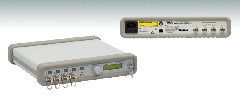
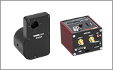
View of Back Panel
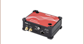
MCSL1C1
4-Channel Laser Source, 1310 nm


Please Wait
| Table 1.1 Key Specifications | |
|---|---|
| Item # | MCLS1C1 |
| Typical Wavelength | 1310 nm |
| Display Power Accuracy | ±10% |
| Current Set Point Resolution | 0.01 mA |
| Temperature Adjust Range | 20.00 to 30.00 °C |
| Temperature Set Point Resolution | ±0.01 °C |
| Noise | <0.5% Typical |
| Rise/Fall Time | <5 µs |
| Modulation Bandwidth | 80 kHz Full Depth of Modulation |
Features
- Independent Temperature Control Gives High Temperature Stability
- Four 1310 nm DFB Laser Output Channels with FC/PC Connectors
- Low Noise Output
- USB Interface
- Low-Profile Package, 2.5" (64 mm) Tall
Thorlabs' Pre-Configured, 4-Channel, Fiber-Coupled Laser Source provides easy coupling and simple control of laser-diode-driven fiber optics. Each system is equipped with four 1310 nm, distributed feedback (DFB) lasers with FC/PC fiber connectors; to discuss custom output connections, contact Tech Sales. These single-frequency laser diodes achieve a 0.1 nm typical linewidth with an excellent side mode suppression ratio (40 dB typical), and provide mode-hop-free, continuous current tuning over the full temperature adjustment range of 20.00 °C to 30.00 °C. The laser source allows more than one channel to be turned on simultaneously; however, it is only possible to adjust the power output of one at a time from the front panel.
Each laser diode is operated from an independent, high-precision, low-noise, constant-current source and temperature control unit. An intuitive LCD interface allows the user to view and set the laser current and temperature independently for each laser. The display indicates the channel number selected, the output wavelength of the source, the operating power calculated from the monitor photodiode, and the actual temperature to which the laser is set.
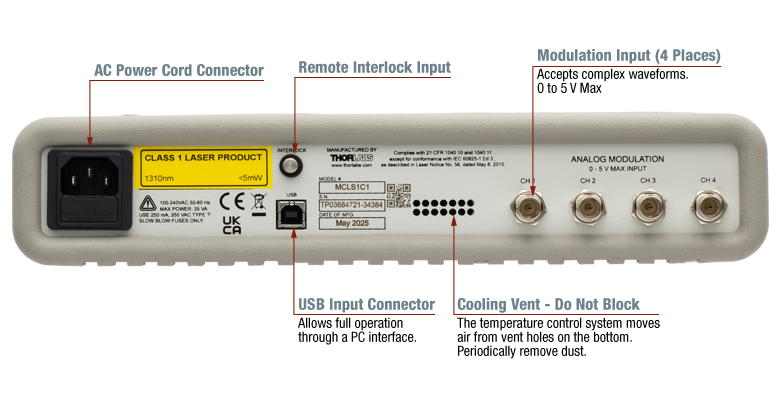
This device incorporates a microcontroller to fully control the laser's optical power and temperature as well as to monitor the system for fault conditions. The laser source includes a USB connection that allows remote enabling, power adjustment, and temperature adjustment. On the rear panel, analog inputs are available to modulate the laser diodes' outputs with an externally generated waveform. To prevent damage, the microcontroller will disable the output if the sum of the analog input and internal set point exceeds the laser limits.
Thorlabs offers the MCLS1-CUSTOM as a customizable, 4-channel laser source, with 31 different laser diode options. We also offer the MCLS2-CUSTOM 4-channel, fiber-coupled, customizable source with alternative laser diode and superluminescent diode (SLD) options. The MCLS2-CUSTOM source features a touchscreen interface and a modulation bandwidth of 200 kHz.
Thorlabs also offers other components suitable for the O-band, including our Praseodymium-Doped Fiber Amplifiers (PDFAs) and Booster Optical Amplifiers. Our fiber-coupled LiNbO3 modulators include FC/PC connectors for easy integration with the MCLS1C1 laser source. For all-in one solutions in high-speed fiber optic test and measurement, we offer reference transmitters, optical transmitter with phase modulators, and calibrated electrical-to-optical converters.
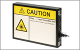
Safety
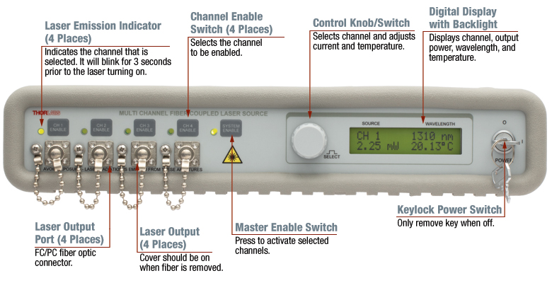
While the output source for the MCLS1C1 falls within the class 1 laser rating, the system was fully designed to meet laser class 3B requirements. There is an interlock located on the rear panel that must be shorted in order for any laser output to be enabled. This can easily be configured to be triggered by doors to disable the lasers in unsafe conditions. The power switch is a keylock system to prevent accidental or unwanted use. Each source has its own enable button allowing the user to choose the light source or sources he wishes to be active, as well as a master enable that must also be set. Each channel includes a green LED indicator to easily determine its current state. There is a 3 second delay before the lasers turn on, and the user is warned by the LED rapidly blinking. The laser must be turned off before connecting or disconnecting a fiber to the output ports.
In the Box
The MCLS1C1 includes a universal power supply allowing operation over 100 - 240 VAC without the need for selecting the line voltage. The fuse access is conveniently located on the rear panel. This unit is supplied with a region-specific U.S. or standard European line cord, the pre-configured laser source with four 1310 nm DFB lasers installed, the manual, and a USB 2.0 Type-A to Type-B cable.
| Performance Specifications | |
|---|---|
| Display Power Accuracy | ±10% |
| Current Set Point Resolution | 0.01 mA |
| Temperature Adjust Range | 20.00 to 30.00 °C |
| Temp Set Point Resolution | ±0.01 °C |
| Noise | <0.5% Typical |
| Rise/Fall Time | <5 µs |
| Modulation Input | 0 - 5 V = 0 - Full Power |
| Modulation Bandwidth | 80 kHz Full Depth of Modulation |
| Laser Source Specifications | |
|---|---|
| Typical Center Wavelength | 1310 nm |
| Wavlength Range | 1290 - 1330 nm |
| Minimum Powera | 1.5 mW |
| Typical Power | 2 mW |
| Laser Type | DFB |
| Built-In Isolator | Yes |
| Monitor Photodiodeb | Yes |
| Fiber | SMF-28e+ |
| Side Mode Suppression Ratio (SMSR) | 35 dB (Min) 40 dB (Max) |
| Laser Mode | Singlec |
| Wavelength Shift over Current | 0.004 nm/mA (Typ.) |
| Wavelength Shift over Temperature | 0.08 nm/°C (Typ.) |
| Slope Efficiencyd | 0.2 W/A |
| Laser Linewidth (-20 dB)d | 0.1 nm (Typ.) 1 nm (Max) |
| General Specifications | |
|---|---|
| AC Input | 100 - 240 VAC, 50 - 60 Hz |
| Input Power | 35 VA Max |
| Fuse Ratings | 250 mA |
| Fuse Type | IEC60127-2/III (250V, Slow Blow Type 'T') |
| Fuse Size | 5 mm x 20 mm |
| Dimensions (W x H x D) | 12.6" x 2.5" x 10.6" (320 mm x 64 mm x 269 mm) |
| Weight | 8.5 lbs (3.9 kg) |
| Operating Temperature | 15 to 35 °C |
| Storage Temperature | 0 to 50 °C |
| Connections and Controls | |
| Interface Control | Optical Encoder with Pushbutton |
| Enable and Laser Select | Keypad Switch Enable with LED Indication |
| Power On | Key Switch |
| Fiber Ports | FC/PC |
| Display | LCD, 16x2 Alphanumeric Characters |
| Input Power Connection | IEC Connector |
| Modulation Input Connector | BNC (Referenced to Chassis) |
| Interlock | 2.5 mm Mono Phono Jack |
| Communications | |
| Communications Port | USB 2.0 |
| Com Connection | USB Type B connector |
| Included Cable | 2 m USB Type-A to Type-B Cable (Replacement Item # USB-A-79) |
For in-depth operation instructions, please view the operating manual. A printed copy of this manual is included with each MCLS1C1 Laser Source.
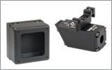
Front Panel
Click to Enlarge
Figure 3.1 Front Panel of the MCLS1C1
Back Panel
Click to Enlarge
Figure 3.3 Back Panel of the MCLS1C1
Viewing Information
Thorlabs' Multi-Channel Laser Sources (MCLS1) use a single four quadrant LCD display to access the information for each output channel (see Figure 3.1 for details). Rotate the control knob to the left of the display to scroll through the channels until the desired channel is selected. The control knob is also a select switch that allows access to the laser current and temperature parameters (see below for more information on the display screen in Figure 3.2).
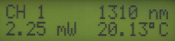
Figure 3.2 LCD Display
- Top Left: Indicates the selected channel.
- Top Right: Indicates the wavelength of the selected channel.
- Bottom Left: Indicates the power level of the laser diode output. If disabled, the power level will read "0.00 mW." If the selected diode does not include a monitor diode, this will read "No PD."
- Bottom Right: Indicates the actual temperature (in °C) that the laser is stabilized to. The default temperature is set to 25.00 °C and is user adjustable. The temperature control is always active and requires 5 to 10 minutes to properly stabilize.
Adjusting the Laser Output Power and Temperature
After selecting a channel, the output power and temperature of the selected laser can be adjusted. The control knob utilizes an intelligent speed control. Turning the knob slowly corresponds to fine adjustment while turning the knob quickly corresponds to coarse adjustment. The laser current adjustment translates to real-time adjustment of output power. The default setting upon first turning on the unit is output power fully off. Note that lasing occurs at the threshold current value, which is different for every source.
Once the desired channel is selected, the Laser Current and Temperature parameters can be adjusted by pressing the control knob in. Pressing in the knob once will select the Laser Current, pressing it a second time will select the Temperature Set Point, and pressing it a third time will revert back to the display mode and lock the selected parameters. The parameter to be adjusted is indicated with blinking text. The resolution is 0.1 mA for the current adjustment and 0.01 °C for the temperature adjustment.
Modulating the Laser Output
The Analog In input can be used to modulate the laser output or to set the laser output remotely using a 5 V power source. The 5 V maximum input corresponds to the maximum calibrated power of each channel. The resulting actual output power is dependent on the set current and operating temperature. In addition, in order to eliminate a dead zone in the power control knob, the output of the unit is offset to the threshold current of the coupled laser diode. Adjusting the knob below threshold will immediately set the current to 0.0 mA (i.e., Standby mode). Therefore, there are two modes of modulation available. Setting the control to "Standby" first allows the analog modulation to utilize the full 0 to 5 V input range. The drawback to this modulation mode is that a minimum voltage is needed to operate above the threshold current. The second mode is to adjust the control knob so that the laser is at or above threshold. The analog modulation voltage will be limited to less than 5 V, but a DC offset will not be required. This DC offset should be kept in mind when using the modulation input since it will limit the actual input voltage range.
Making the Safety Interlock Connections
The MCLS1 series of laser sources are equipped with a remote interlock connector located on the rear panel. All units have this feature regardless of their FDA and IEC classifications. In order to enable the MCLS1 source, a short circuit must be applied across the terminals of the Remote Interlock connector. In practice this connection is made available to allow the user to connect a remote-actuated switch to the connector (i.e., an open door indicator). The switch (which must be normally open) has to be closed in order for the unit to be enabled. Once the switch is in an open state, the MCLS1 source will automatically shut down. If the switch returns to a closed condition, the MCLS1 source must be re-enabled at the unit by pressing the "Master Enable" switch.
Figure 3.4 Interlock Mating Connector
| Specification | Value |
|---|---|
| Type of Mating Connector | 2.5 mm Mono Phono Jack |
| Open Circuit Voltage | +5 VDC with Respect to Chassis Ground |
| Short Circuit Current | ~8 mA DC |
| Connector Polarity | Tip is +5 V, Barrel is Ground |
| Interlock Switch Requirementa | Must be Normally Open Dry Contacts |
Software
Version 3.0.1
Software package to operate Thorlabs' MCLS1 Series 4-Channel Laser Sources, including a GUI, drivers, and LabVIEW/C++/Python SDK for secondary development.
Laser Safety and Classification
Safe practices and proper usage of safety equipment should be taken into consideration when operating lasers. The eye is susceptible to injury, even from very low levels of laser light. Thorlabs offers a range of laser safety accessories that can be used to reduce the risk of accidents or injuries. Laser emission in the visible and near infrared spectral ranges has the greatest potential for retinal injury, as the cornea and lens are transparent to those wavelengths, and the lens can focus the laser energy onto the retina.
 |
 |
 |
 |
 |
 |
 |
 |
 |
Safe Practices and Light Safety Accessories
- Laser safety eyewear must be worn whenever working with Class 3 or 4 lasers.
- Regardless of laser class, Thorlabs recommends the use of laser safety eyewear whenever working with laser beams with non-negligible powers, since metallic tools such as screwdrivers can accidentally redirect a beam.
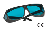
- Laser goggles designed for specific wavelengths should be clearly available near laser setups to protect the wearer from unintentional laser reflections.
- Goggles are marked with the wavelength range over which protection is afforded and the minimum optical density within that range.
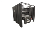
- Laser Safety Curtains and Laser Safety Fabric shield other parts of the lab from high energy lasers.
- Blackout Materials can prevent direct or reflected light from leaving the experimental setup area.
- Thorlabs' Enclosure Systems can be used to contain optical setups to isolate or minimize laser hazards.
- A fiber-pigtailed laser should always be turned off before connecting it to or disconnecting it from another fiber, especially when the laser is at power levels above 10 mW.
- All beams should be terminated at the edge of the table, and laboratory doors should be closed whenever a laser is in use.
- Do not place laser beams at eye level.
- Carry out experiments on an optical table such that all laser beams travel horizontally.
- Remove unnecessary reflective items such as reflective jewelry (e.g., rings, watches, etc.) while working near the beam path.
- Be aware that lenses and other optical devices may reflect a portion of the incident beam from the front or rear surface.
- Operate a laser at the minimum power necessary for any operation.
- If possible, reduce the output power of a laser during alignment procedures.
- Use beam shutters and filters to reduce the beam power.
- Post appropriate warning signs or labels near laser setups or rooms.
- Use a laser sign with a lightbox if operating Class 3R or 4 lasers (i.e., lasers requiring the use of a safety interlock).
- Do not use Laser Viewing Cards in place of a proper Beam Trap.
Laser Classification
Lasers are categorized into different classes according to their ability to cause eye and other damage. The International Electrotechnical Commission (IEC) is a global organization that prepares and publishes international standards for all electrical, electronic, and related technologies. The IEC document 60825-1 outlines the safety of laser products. A description of each class of laser is given below:
| Class | Description | Warning Label |
|---|---|---|
| 1 | This class of laser is safe under all conditions of normal use, including use with optical instruments for intrabeam viewing. Lasers in this class do not emit radiation at levels that may cause injury during normal operation, and therefore the maximum permissible exposure (MPE) cannot be exceeded. Class 1 lasers can also include enclosed, high-power lasers where exposure to the radiation is not possible without opening or shutting down the laser. | 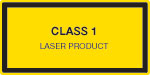 |
| 1M | Class 1M lasers are safe except when used in conjunction with optical components such as telescopes and microscopes. Lasers belonging to this class emit large-diameter or divergent beams, and the MPE cannot normally be exceeded unless focusing or imaging optics are used to narrow the beam. However, if the beam is refocused, the hazard may be increased and the class may be changed accordingly. |  |
| 2 | Class 2 lasers, which are limited to 1 mW of visible continuous-wave radiation, are safe because the blink reflex will limit the exposure in the eye to 0.25 seconds. This category only applies to visible radiation (400 - 700 nm). |  |
| 2M | Because of the blink reflex, this class of laser is classified as safe as long as the beam is not viewed through optical instruments. This laser class also applies to larger-diameter or diverging laser beams. |  |
| 3R | Class 3R lasers produce visible and invisible light that is hazardous under direct and specular-reflection viewing conditions. Eye injuries may occur if you directly view the beam, especially when using optical instruments. Lasers in this class are considered safe as long as they are handled with restricted beam viewing. The MPE can be exceeded with this class of laser; however, this presents a low risk level to injury. Visible, continuous-wave lasers in this class are limited to 5 mW of output power. |  |
| 3B | Class 3B lasers are hazardous to the eye if exposed directly. Diffuse reflections are usually not harmful, but may be when using higher-power Class 3B lasers. Safe handling of devices in this class includes wearing protective eyewear where direct viewing of the laser beam may occur. Lasers of this class must be equipped with a key switch and a safety interlock; moreover, laser safety signs should be used, such that the laser cannot be used without the safety light turning on. Laser products with power output near the upper range of Class 3B may also cause skin burns. |  |
| 4 | This class of laser may cause damage to the skin, and also to the eye, even from the viewing of diffuse reflections. These hazards may also apply to indirect or non-specular reflections of the beam, even from apparently matte surfaces. Great care must be taken when handling these lasers. They also represent a fire risk, because they may ignite combustible material. Class 4 lasers must be equipped with a key switch and a safety interlock. |  |
| All class 2 lasers (and higher) must display, in addition to the corresponding sign above, this triangular warning sign. |  |
|
| Posted Comments: | |
| No Comments Posted |