 Products Home / Active Optical Devices / Optical Amplifiers / O-Band Booster Optical Amplifiers (BOAs), 1285 - 1350 nm
O-Band Booster Optical Amplifiers (BOAs), 1285 - 1350 nm
- Polarization-Dependent Booster Optical Amplifiers
- SM or PM Fiber-Pigtailed Butterfly Package
- High Saturation Power (>15 dBm)
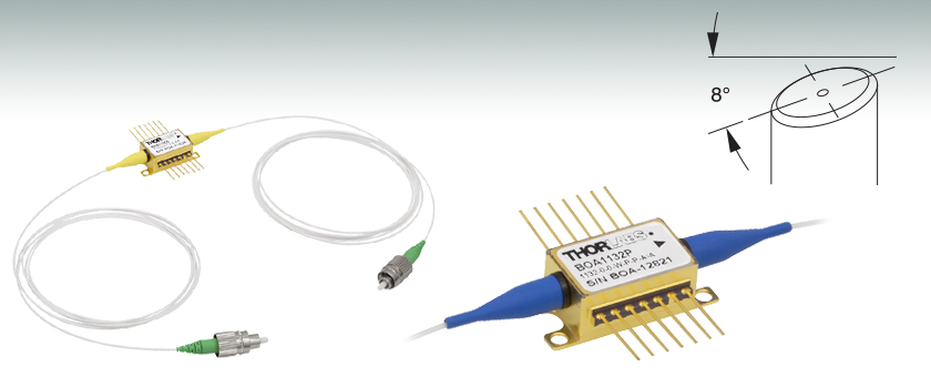
BOA1130S
High-Power BOA with SM Fiber and FC/APC Connectors
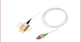
BOA1132P
BOA with PM Fiber and FC/APC Connectors, Closeup of Butterfly Package Shown
FC/APC Connectors


Please Wait
| Optical Amplifier Selection Guide |
|---|
| 780 - 795 nm BOAs |
| 830 nm BOAs |
| 930 nm BOAs |
| 980 nm BOAs |
| 1050 nm BOAs |
| 1210 nm BOAs |
| 1250 nm BOAs |
| O-Band (1285 - 1350 nm) BOAs |
| E-Band (1410 nm) BOAs |
| C-Band (1550 nm) BOAs and SOAs |
| L-Band (1590 - 1625 nm) BOAs |
| 1685 nm BOAs |
| 1700 nm BOAs |
Click to Enlarge
Figure 1.1 When current is applied across the ridge waveguide, excited state electrons are stimulated by input light, leading to photon replication and signal gain.
Features
- Polarization Dependent: Amplifies Only One Polarization State
- Center Wavelengths Available Between 1285 nm and 1350 nm
- Available with Either SM or PM Fiber Pigtails (1.5 m)
- 2.0 mm Narrow Key FC/APC Connectors
- 2.5 dB Coupling Loss at Each Chip End
- High Saturation Power (>15 dBm), High Efficiency
- 3 dB Bandwidth: 70 nm, 80 nm, 82 nm, or 87 nm (Typical)
- AR-Coated End Faces on Chip (R < 0.1%)
- Typical Applications: Boosting Laser Transmitters, Compensating for Transmit
MUX/DeMUX Insertion Loss, and Optical Shutters
Booster Optical Amplifiers (BOAs) are single-pass, traveling-wave amplifiers that perform well with both monochromatic and multi-wavelength signals. Since BOAs only amplify one state of polarization, they are best suited for applications where the input polarization of the light is known. For applications where the input polarization is unknown or fluctuates, a Semiconductor Optical Amplifier (SOA) is required. However, the gain, noise, bandwidth, and saturation power specifications of a BOA are superior to that of an SOA because of the design features that make the SOA polarization insensitive.
The BOA consists of a highly-efficient InP/InGaAsP Multiple Quantum Well (MQW) layer structure. As seen in Figure 1.1, the input and output of the amplifier is coupled to the reliable ridge waveguide on the optical amplifier chip. Losses typically range from 1.5 to 2.5 dB at both the fiber-to-chip and chip-to-fiber couplings. These coupling losses affect the total gain, noise figure (NF), and saturation power (Psat). While the gain produced by the amplifier exceeds that of the losses, these losses remain an important factor in determining the device's performance. For instance, a 1 dB drop in input coupling efficiency increases the noise figure by 1 dB. Alternatively, a 1 dB drop in output coupling decreases the saturation power by 1 dB.
The device is contained in a standard 14-pin butterfly package with either SM or PM fiber pigtails that are terminated with FC/APC connectors. The connector key is aligned to the slow axis on all PM fiber pigtailed models. Optional polarization-maintaining isolators at the input, output, or both input/output are also available (specifications may vary with different configurations). Please contact Tech Support to order such a device.
Thorlabs also offers other components suitable for the O-Band, including our high-speed transmitter and receivers and Praseodymium-Doped Fiber Amplifier (PDFA). The PDFA should be used for applications requiring O-band signal transmission amplficiation with low-noise and minimal signal latency.
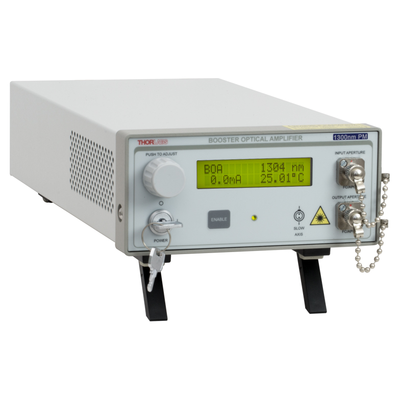
Click to Enlarge
Figure 1.2 Our BOA1132P optical amplifier is also available in the S9FC1132P benchtop optical amplifier.
Mount and Driver Options
These butterfly packages are compatible with the CLD1015 laser diode mount with integrated controller and TEC. When operating the BOAs on this page with the CLD1015, the orientation for type 1 pin configurations should be used. They are also compatible with the LM14TS and LM14S2 mounts, which can be used with our laser diode, TEC, and combined current/TEC controllers. When operating these lasers in environments with more than 5 °C variation in temperature, we recommend using the LM14TS mount, which provides active control of the butterfly package's case temperature to stabilize the amplifier's output wavelength and power.
Center Wavelength Note
The center wavelength (CWL) of the amplified spontaneous emission (ASE) spectrum in broadband semiconductor devices such as optical amplifiers may show variation between lots. Please refer to the Specs tab for the CWL tolerances of each particular model. For applications in which a specific ASE center wavelength is a critical concern, please contact Tech Support for information on the CWL of currently available lots.
| Item #a,b | Center Wavelength | 3 dB Bandwidth | Saturated Output Power (@ -3 dB) |
Small Signal Gain (@ Pin = -20 dBm) |
Noise Figure |
|---|---|---|---|---|---|
| BOA1130S and BOA1130P | 1285 nm | 87 nm | 19 dBm | 30 dB | 7 dB |
| BOA1310S and BOA1310P | 1290 nmc | 82 nm | 20.5 dBmd,e | 32 dB | 7.0 dB |
| BOA1132S and BOA1132P | 1300 nm | 87 nm | 17 dBm | 30 dB | 7 dB |
| BOA1017S and BOA1017P | 1310 nm | 70 nm | 17 dBm | 28 dB | 7.0 dB |
| BOA1036S and BOA1036P | 1350 nm | 80 nm | 15 dBm | 23 dB | 8 dB |
| Item # | Symbol | BOA1130S and BOA1130P | ||
|---|---|---|---|---|
| Min | Typical | Max | ||
| Operating Current | IOP | - | 700 mA | 750 mA |
| Center Wavelength | λC | 1265 nm | 1285 nm | 1295 nm |
| Optical 3 dB Bandwidth | BW | 80 nm | 87 nm | - |
| Saturation Output Powera (@ -3 dB) | PSAT | 18 dBm | 19 dBm | - |
| Optical Input Power | PIN | - | - | 70 mW |
| Small Signal Gain (@ Pin = -20 dBm, λ = 1312 nm) |
G | 27 dB | 30 dB | - |
| Gain Ripple (RMS) @ IOP | ΔG | - | 0.2 dB | 0.3 dB |
| Noise Figure | NF | - | 7 dB | 9 dB |
| Forward Voltage | VF | - | 1.6 V | 2.0 V |
| TEC Operation (Typ./Max @ TCASE = 25 °C / 70 °C) | ||||
| TEC Current | ITEC | - | 0.4 A | 1.5 A |
| TEC Voltage | VTEC | - | 0.5 V | 4.0 V |
| Thermistor Resistance | RTH | - | 10 kΩ | - |
| Item # | Symbol | BOA1310S and BOA1310P | ||
|---|---|---|---|---|
| Min | Typical | Max | ||
| Operating Current | IOP | - | 900 | 1000 mA |
| Center Wavelengtha | λC | 1275 nm | 1290 nm | 1305 nm |
| Optical 3 dB Bandwidth | BW | 75 nm | 82 nm | - |
| Saturation Output Powerb (@ -3 dB, IOP, λ = 1312 nm) |
PSAT | 20 dBm | 20.5 dBm | - |
| Optical Input Power | PIN | - | - | 70 mW |
| Small Signal Gain (@ Pin = -20 dBm, IOP, λ = 1312 nm) |
G | 28.5 dB | 32 dB | - |
| Gain Ripple (RMS, @ IOP) | ΔG | - | 0.12 dB | 0.35 dB |
| Noise Figure (@ IOP, λ = 1312 nm) | NF | - | 7.0 dB | 9.5 dB |
| Forward Voltage (@ IOP) | VF | - | 1.5 V | 2.0 V |
| TEC Operation (Typ./Max @ TCASE = 25 °C / 70 °C) | ||||
| TEC Current | ITEC | - | 0.5 A | 1.5 A |
| TEC Voltage | VTEC | - | 0.7 V | 4.0 V |
| Thermistor Resistance | RTH | - | 10 kΩ | - |
| Item # | Symbol | BOA1132S and BOA1132P | ||
|---|---|---|---|---|
| Min | Typical | Max | ||
| Operating Current | IOP | - | 700 mA | 750 mA |
| Center Wavelength | λC | 1290 nm | 1300 nm | 1315 nm |
| Optical 3 dB Bandwidth | BW | 80 nm | 87 nm | - |
| Saturation Output Powera (@ -3 dB) | PSAT | 15 dBm | 17 dBm | - |
| Optical Input Power | PIN | - | - | 70 mW |
| Small Signal Gain (@ Pin = -20 dBm, λ = 1312 nm) |
G | 27 dB | 30 dB | - |
| Gain Ripple (RMS) @ IOP | ΔG | - | 0.2 dB | 0.3 dB |
| Noise Figure | NF | - | 7 dB | 9 dB |
| Forward Voltage | VF | - | 1.6 V | 2.0 V |
| TEC Operation (Typ./Max @ TCASE = 25 °C / 70 °C) | ||||
| TEC Current | ITEC | - | 0.4 A | 1.5 A |
| TEC Voltage | VTEC | - | 0.5 V | 4.0 V |
| Thermistor Resistance | RTH | - | 10 kΩ | - |
| Item # | Symbol | BOA1017S and BOA1017P | ||
|---|---|---|---|---|
| Min | Typical | Max | ||
| Operating Current | IOP | - | 600 mA | 750 mA |
| Center Wavelength | λC | 1290 nm | 1310 nm | 1330 nm |
| Optical 3 dB Bandwidth | BW | 60 nm | 70 nm | - |
| Saturation Output Powera (@ -3 dB) | PSAT | 15 dBm | 17 dBm | - |
| Optical Input Power | PIN | - | - | 70 mW |
| Small Signal Gain (@ Pin = -20 dBm, IOP, λ = 1312 nm) |
G | 24 dB | 28 dB | - |
| Gain Ripple (RMS) @ IOP | ΔG | - | 0.1 dB | 0.25 dB |
| Polarization Extinction Ratio | PER | - | 16 dB | - |
| Noise Figure | NF | - | 7.0 dB | 9.0 dB |
| Forward Voltage | VF | - | 1.4 V | 1.6 V |
| TEC Operation (Typ./Max @ TCASE = 25 °C / 70 °C) | ||||
| TEC Current | ITEC | - | 0.15 A | 1.5 A |
| TEC Voltage | VTEC | - | 0.35 V | 4.0 V |
| Thermistor Resistance | RTH | - | 10 kΩ | - |
| Item # | Symbol | BOA1036S and BOA1036P | ||
|---|---|---|---|---|
| Min | Typical | Max | ||
| Operating Current | IOP | - | 700 mA | 750 mA |
| Center Wavelength | λC | 1330 nm | 1350 nm | 1370 nm |
| Optical 3 dB Bandwidth | BW | 65 nm | 80 nm | - |
| Saturation Output Powera (@ -3 dB, λ = 1312 nm) |
PSAT | 13 dBm | 15 dBm | - |
| Optical Input Power | PIN | - | - | 70 mW |
| Small Signal Gain (@ Pin = -20 dBm, IOP, λ = 1312 nm) |
G | 20 dB | 23 dB | - |
| Gain Ripple (RMS) @ IOP | ΔG | - | - | 0.3 dB |
| Noise Figure | NF | - | 8 dB | 11 dB |
| Forward Voltage | VF | - | 1.6 V | 2.0 V |
| TEC Operation (Typ./Max @ TCASE = 25 °C / 70 °C) | ||||
| TEC Current | ITEC | - | 0.4 A | 1.5 A |
| TEC Voltage | VTEC | - | 0.5 V | 4.0 V |
| Thermistor Resistance | RTH | - | 10 kΩ | - |
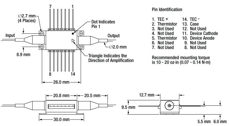
Mechanical Drawing and Pin Assignments
Note: All plots illustrate typical performance, and individual units may have slightly different performance, within the parameters outlined on the Specs tab.
BOA1130S and BOA1130P Graphs
The gain vs. output power plot shown below for the BOA1130S and BOA1130P was measured with an operating current of 700 mA and an input wavelength of 1312 nm. The amplified spontaneous emission (ASE) spectrum was also measured at an operating current of 700 mA.
BOA1310S and BOA1310P Graphs
The gain vs. output power plot swas measured for the BOA1310P optical amplifier with an operating current of 900 mA and an input wavelength of 1312 nm. The amplified spontaneous emission (ASE) spectrum was also measured at an operating current of 900 mA. The BOA1310S shows similar performance (see the Spec Sheet by clicking on the red docs icon below for more information).
BOA1132S and BOA1132P Graphs
The gain vs. output power plot shown below for the BOA1132S and BOA1132P was measured with an operating current of 700 mA and an input wavelength of 1312 nm. The amplified spontaneous emission (ASE) spectrum was also measured at an operating current of 700 mA.

BOA1017P and BOA1017S Graphs
The gain vs. output power plot shown below for the BOA1017P and BOA1017S was measured with an operating current of 600 mA and an input wavelength of 1312 nm. The amplified spontaneous emission (ASE) spectrum was also measured at an operating current of 600 mA.
BOA1036P and BOA1036S Graphs
The gain vs. output power plot shown below for the BOA1036P and BOA1036S was measured with an operating current of 700 mA and an input wavelength of 1312 nm. The amplified spontaneous emission (ASE) spectrum was also measured at an operating current of 700 mA. Please note: the ripple on the ASE spectrum curve below is due to water absorption during the test and not indicative of the performance of the device.
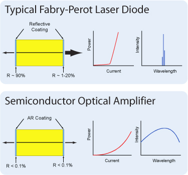
Booster optical amplifiers (BOAs) and semiconductor optical amplifiers (SOAs) are single-pass, traveling-wave amplifiers that perform well with both monochromatic and multi-wavelength signals. Since BOAs only amplify one state of polarization, they are best suited for applications where the input polarization of the light is known. For applications where the input polarization is unknown or fluctuates, a Semiconductor Optical Amplifier (SOA) is required. However, the gain, noise, bandwidth, and saturation power specifications of a BOA are superior to that of a SOA because of the design features that make the SOA polarization insensitive.
BOAs and SOAs are similar in design to Fabry-Perot Laser Diodes, the difference being that Fabry-Perot laser diodes have reflective coatings on both end faces of the semiconductor chip. The optical feedback from the reflective end faces establishes a cavity in which lasing can occur. SOAs and BOAs have an anti-reflection (AR) coating on both end faces of the semiconductor chip. The AR coatings limit the optical feedback into the chip so that lasing does not occur.
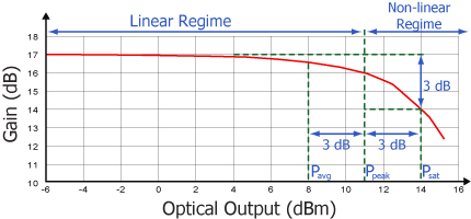
As is typical for all amplifiers, BOAs/SOAs operate in two regimes: a linear, flat, constant gain regime and a non-linear, saturated output regime. When used to amplify a modulated signal, the linear regime is typically used to eliminate pattern-dependent distortion, multi-channel cross-talk, and transient response issues common to EDFAs. The non-linear regime is used to take advantage of the highly non-linear attributes of the semiconductor gain medium (cross-gain modulation, cross phase modulation) to perform wavelength conversion, optical 3R regeneration, header recognition, and other high-speed optical signal processing functions.
For a continuous wave input signal, the amount of power that can be produced by the amplifier is determined by the saturation output power (Psat) parameter. Psat is defined as the output power at which the small-signal gain has been compressed by 3 dB. The maximum amount of CW power that can be extracted is approximately 3 dB higher than the saturation power.
| Posted Comments: | |
user
(posted 2024-09-09 14:07:25.153) On the provided ASE spectrum graphs the y axis is in dB. Can you clarify the unit and if you are using a specific resolution bandwidth for these measurements? I would expect the y axis to be something like dBm/nm or similar.
Thank you! jpolaris
(posted 2024-09-11 03:44:29.0) Thank you for contacting Thorlabs. The ASE spectrum graphs we provide use a relative dB measurement. Meaning, it is an arbitrary scale. This is because when we take this measurement with an optical spectrum analyzer (OSA) there is significant loss when coupling into the instrument. The OSA measurement is in units of dBm. The ASE spectrum graphs that we provide are actually dBm versus wavelength, but you would need to apply an appropriate scale factor that accounts for the OSA loss to find the actual output power from ASE. Guilherme Garcia
(posted 2022-03-23 10:24:54.263) I am using a BOA1130P - Booster Optical Amplifier.
I would like to have a better understanding for the behavior of this component, and was wondering if you could give me directions about the original work published on this area?
Like papers published on specialized journals or conferences.
Thank you very much
Guilherme jdelia
(posted 2022-03-24 01:51:08.0) Thank you for contacting Thorlabs. I have contacted you directly to recommend some literature for this subject area. Generally, Booster Optical Amplifiers (BOA's) and Semiconductor Optical Amplifiers (SOA'S) are the same, Thorlabs uses the term "BOA" to describe a special case of a SOA that is polarization dependent. Kenny Wong
(posted 2020-04-10 02:01:36.62) I am looking for a component to amplify the output from my tunable laser (Santec TSL 550) from around 12dBm to above 16dBm. Can your BOA do the job? YLohia
(posted 2020-04-23 12:43:45.0) Thank you for contacting Thorlabs. What specific wavelength range do you plan on using from your laser for amplification? Are you planning on continuously sweeping through the wavelengths? Or are you planning on discretely stepping through the wavelengths over a long period of time? I had contacted you at the time of your original post with these questions and did not receive a response. If you would like to continue this discussion, please email us at techsupport@thorlabs.com. Luluzi Lu
(posted 2019-11-05 14:14:29.587) How about the polarization dependent gain? And do u sell the o-band SOA chip? YLohia
(posted 2019-11-12 12:26:37.0) Hello, thank you for contacting Thorlabs. What specific BOA are you asking for the PDG of? Unfortunately, we currently do not offer polarization insensitive SOAs in the O-band. Chih Liu
(posted 2019-03-25 16:05:37.4) Dear Sir,
Could you please let me know the spontaneous emission power of the BOA1017S? We are planing to build an system by using this amplifier.
Thank you
Chih YLohia
(posted 2019-03-28 05:03:49.0) Hello Chih, thank you for contacting Thorlabs. I have reached out to you directly with a plot of the total ASE power vs drive current. kkmion
(posted 2018-11-28 22:31:19.793) Can the BOA be driven using CLD1015? YLohia
(posted 2018-11-29 08:50:59.0) Yes, the BOA can be driven using the CLD1015. This information is given on the Overview tab of this page. jeffrey.o.white6.civ
(posted 2016-05-02 09:02:18.21) I would like to know how much spontaneous emission comes out when, for example, 4mW is input, and 40mW (or max output) is produced. Do you have any output spectra representative of these devices for a seed in the O-band. Thx.
Jeff White besembeson
(posted 2016-05-04 02:53:59.0) Response from Bweh at Thorlabs USA: For a 700mA drive current, we have a plot for the amplified spontaneous emission spectrum (ASE) under the "Graphs" tab. The gain variation with output power was measured at 1312nm, which is in the O-band. udaytronic
(posted 2016-04-26 07:28:56.21) Hi,
I was looking for maximum input optical power for those amplifiers in the specs. But I don't see them. Could you please let me know where to find or may be you can update them.
Thanking you besembeson
(posted 2016-04-26 09:46:56.0) Response from Bweh at Thorlabs USA: We do specify the saturation power, and the maximum output power that can be extracted from any of these devices is 3dB higher than the saturation power. So you should keep your input power to a maximum level with the amplification factor (which is wavelength and drive current dependent) and saturation power in mind. |