 Products Home
Multispectral Imaging System
- Multispectral Imaging System with 12 Spectral Channels
- Monochrome CMOS Camera with a 2.3 MP Sensor
- Global Shutter for Imaging Fast-Moving Objects
- Filters Available for VIS, VIS/NIR, and NIR Applications
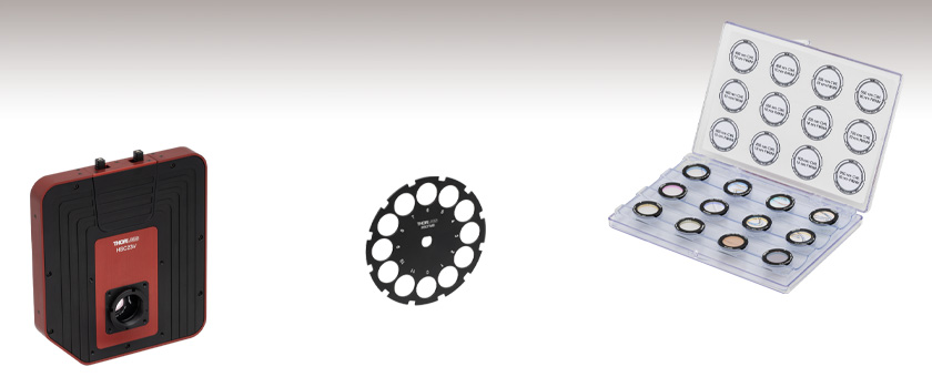
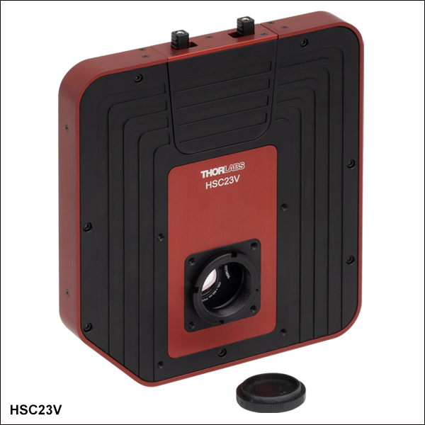
HSC23V
Multispectral Imaging System
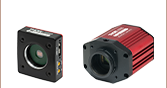
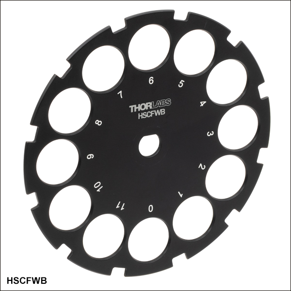
HSCFWB
Empty Filter Wheel for Multispectral Imaging System
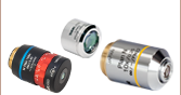
HSCFW2
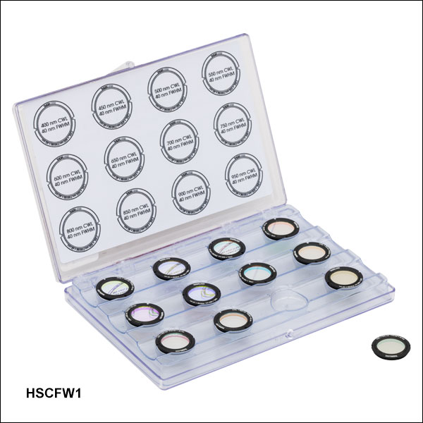
VIS/NIR Filter Kit,
10 nm FWHM


Please Wait
Building a Complete Multispectral Imaging System
A complete multispectral imaging system must include:
- 1x HSC23V Multispectral Imaging System
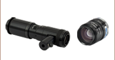
- 1x C-Mount Lens
- 1x Filter Kit
- 1x PC for Running the Multispectral Imaging System Software (User Supplied)
Applications
- Multispectral Imaging
- Materials Inspection
- VIS/NIR Imaging
- Machine Vision
- Security and Defense
- Medical Imaging
- Screening, Measurement, and Authentication
Features
- 1/1.2" Format, Monochrome CMOS 1936 x 1216 Pixel (2.3 MP) Sensor
- High Quantum Efficiency (71%)
- Global Shutter
- USB 3.0 Interface
- Software for Windows® 10 (64-Bit), and 11 Operating Systems
- Compatible with 30 mm or 60 mm Cage Systems
- 1/4"-20 Tapped Holes for Post Mounting
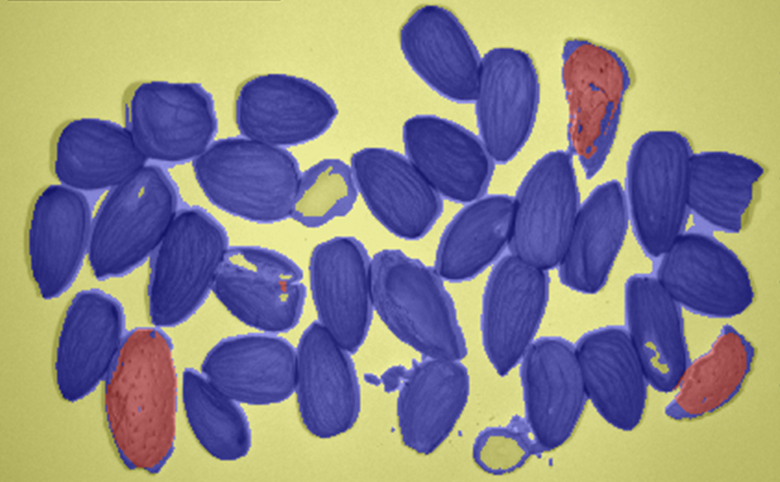
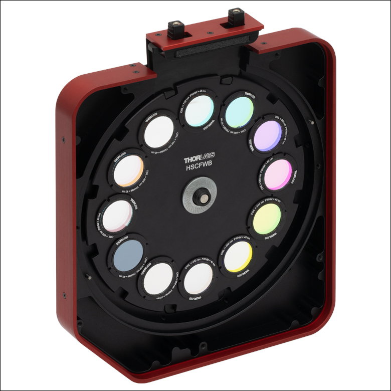
Thorlabs' HSC23V multispectral imaging system features a 1/1.2" format, monochrome CMOS sensor, and is designed to simplify the capture of spectral images (data cubes) with the help of user-configurable filter sets. The system features a 12-slot wheel (see Figure 1.2), which allows the imaging system to generate a data cube with 12 spectral channels. These data cubes enable spatial spectroscopy of a user’s samples. By selecting wavelengths relevant to an application, users can develop a measurement system capable of classifying various analytes or quantifying the response in a particular wavelength range. The global shutter of the imaging system scans the entire field of view simultaneously, allowing for imaging of fast-moving objects. The imaging system is powered by a 12 VDC, 4 A input. A DS12 power supply is provided with each imaging system; see the Shipping List tab for a complete list of items included with the device.
Click to Enlarge
Figure 1.1 The HSC23V Multispectral Imaging System used to detect pieces of nutshells (orange) among edible nuts (blue).
 Click to Enlarge
Figure 1.2 The 12-slot filter wheel of the HSC23V Multispectral Imaging System
12-Slot Filter Wheel and Filter Kits
The HSC23V imaging system features a 12-slot filter wheel, that allows customers to tailor their system to their own application. Filter kits are sold separately as sets of twelve (12) filters for various wavelength ranges (VIS, VIS/NIR, or NIR), as well as various full width at half maximum (FWHM) bandwidths. Filters from different kits can be mixed if not all filters are required from a single set to customize the system for a given application. Transmission spectra for the different filter kits can be found in the Filter Graphs tab, while more detailed specifications on each filter may be found below. An extra HSCFWB empty filter wheel may be purchased to make swapping between sets easier.
Note: The dimensions of the filters in these kits have been optimized to be compatible with the multispectral imaging system. Other Thorlabs filters are not compatible with the HSC23V Multispectral Imaging System. Only filters from the kits sold below should be used with the imaging system.
Mounting Options
The imaging system can be attached directly to our 30 mm and 60 mm cage systems via the 4-40 mounting holes on the front of the housing. Four 1/4"-20 tapped holes (two on the bottom with a spacing of 2", two on the side with a spacing of 1") on the housing provide compatibility with imperial Ø1/2" Posts, Ø1" Posts and many standard tripod mounts. For more information about mounting the HSC23V imaging system, see the Mounting Options tab.
Multispectral Imaging System Software
Each imaging system includes a USB 3.0 interface for compatibility with most computers. With the 12-slot wheel, the imaging system can generate a data cube with 12 spectral channels. This image capture is performed using the Thorlabs Multispectral Imaging System software. The software can also be used for easier replacement of filters in the filter wheel of the imaging system. Visit the Software tab to download the latest software.
Click for Details
Figure 2.2 Mechanical Drawing of the HSC23V Multispectral Imaging System
| Table 2.1 CMOS Sensor Specifications | |||||
|---|---|---|---|---|---|
| Item # | HSC23V | ||||
| Sensor Type | Monochrome CMOS | ||||
| Wavelength Range | 400 - 1000 nm | ||||
| Number of Active Pixels | 1936 (W) x 1216 (H) | ||||
| Pixel Size | 5.86 µm x 5.86 µm | ||||
| Imaging Area | 11.34 mm (W) x 7.13 mm (H) | ||||
| Optical Format | 1/1.2" (13.4 mm Diagonal) | ||||
| Peak Quantum Efficiency | 71% at 500 nm | ||||
| Shutter Type | Global | ||||
| ADCa | 12 Bit | ||||
| Max Frame Rate at Full Resolution | 40 fps | ||||
| Dark Current Compensation | Automatic | ||||
| Table 2.3 Imaging Specifications | |||||
|---|---|---|---|---|---|
| Item # | HSC23V | ||||
| Filter-to-Filter Time | 160 ms | ||||
| Exposure Time | 0 - 10000 ms (0.1 ms Increments) | ||||
| ADCa Resolution | 12 Bit | ||||
| Vertical and Horizontal Digital Binning |
1 x 1 to 5 x 5 | ||||
| Region of Interest (ROI) | 1936 (W) x 1216 (H) Pixels Max | ||||
| Table 2.4 General Specifications | |||||
|---|---|---|---|---|---|
| Item # | HSC23V | ||||
| Power Consumptiona | 2.1 W | ||||
| Operating Temperatureb | 10 °C to 40 °C | ||||
| Storage Temperature | 0 °C to 55 °C | ||||
Click to Enlarge
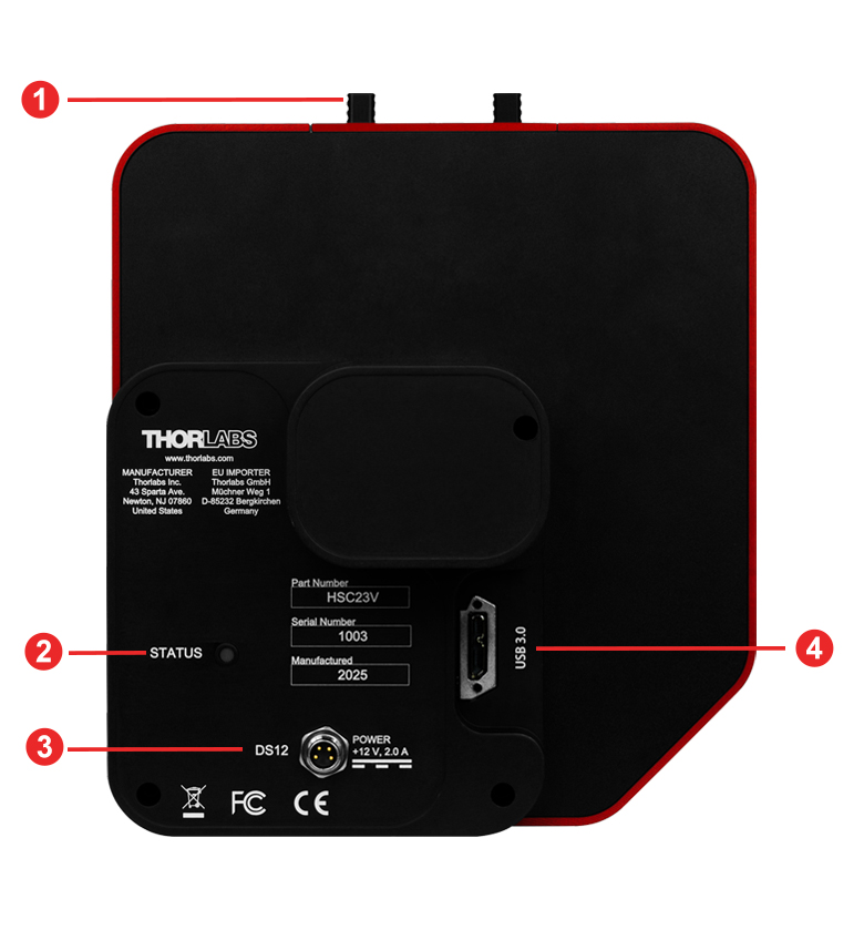
Figure 3.2 HSC23V Multispectral Imaging System Back Panel
| Callout | Description |
|---|---|
| 1 | Filter Hatch |
| 2 | Power Indicator LED |
| 3 | Four-Pin Power Connector |
| 4 | USB 3.0 Connector |
Click to Enlarge
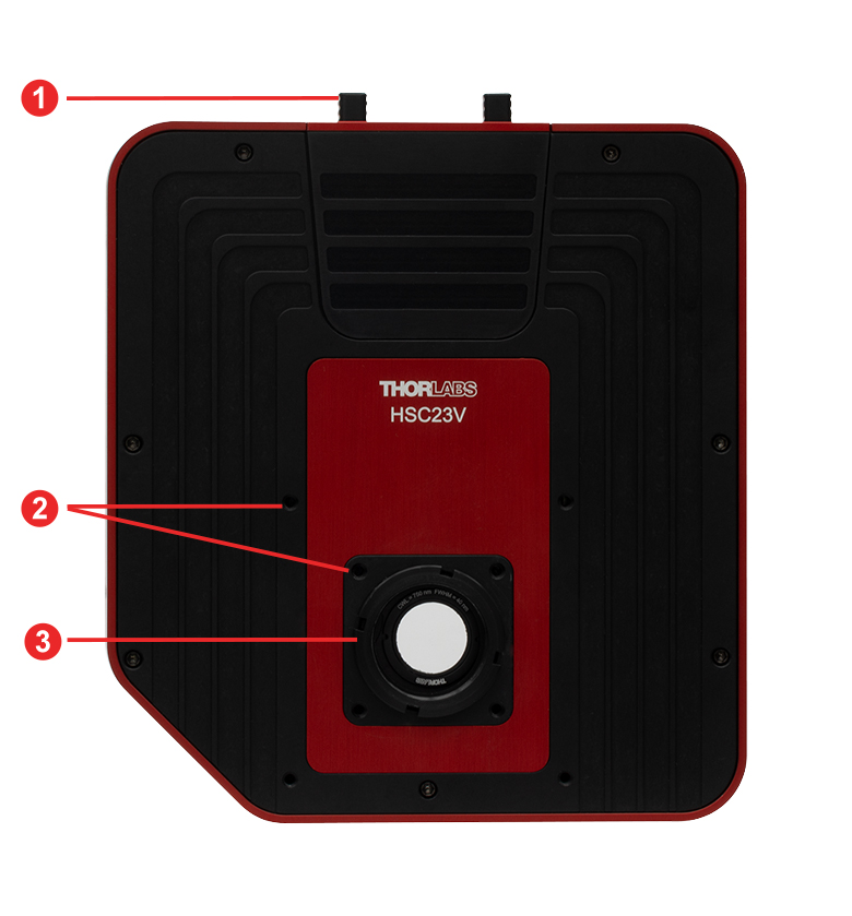
Figure 3.1 HSC23V Multispectral Imaging System Front Panel
| Callout | Description |
|---|---|
| 1 | Filter Hatch |
| 2 | Cage Assembly Rod Holes (4-40 Tapped Holes, 8 Total) |
| 3 | C-Mount Adapter |
Figures 4.1 to 4.4 show the transmission plots for filters included in the HSCFW1, HSCFW2, HSCFW3, and HSCFW4 filter kits.
Click to Enlarge
Click for Raw Data
Figure 4.2 The plot above shows the transmission of filters in the HSCFW2 filter kit.

Click to Enlarge
Click for Raw Data
Figure 4.1 The plot above shows the transmission of filters in the HSCFW1 filter kit.
Click to Enlarge
Click for Raw Data
Figure 4.4 The plot above shows the transmission of filters in the HSCFW4 filter kit.
Click to Enlarge
Click for Raw Data
Figure 4.3 The plot above shows the transmission of filters in the HSCFW3 filter kit.
Multispectral Imaging System Mounting Features |
||||
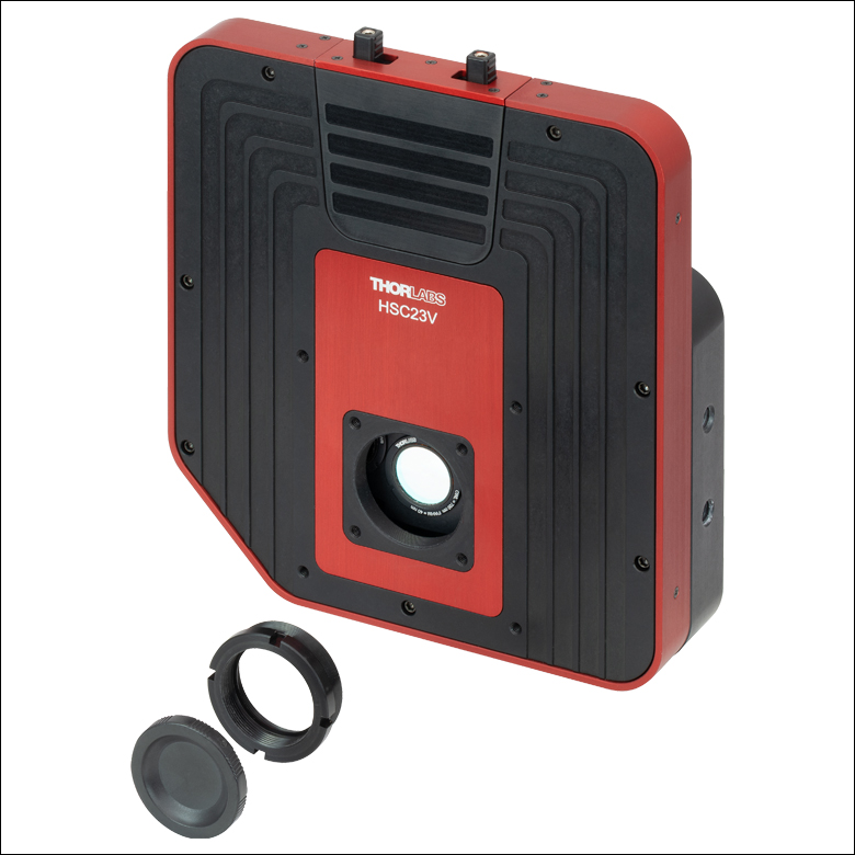 Click to Enlarge Figure 5.1 Removing the C-mount adapter and locking ring exposes the SM1 (1.035"-40) threading that can be used for custom assemblies using standard Thorlabs components. |
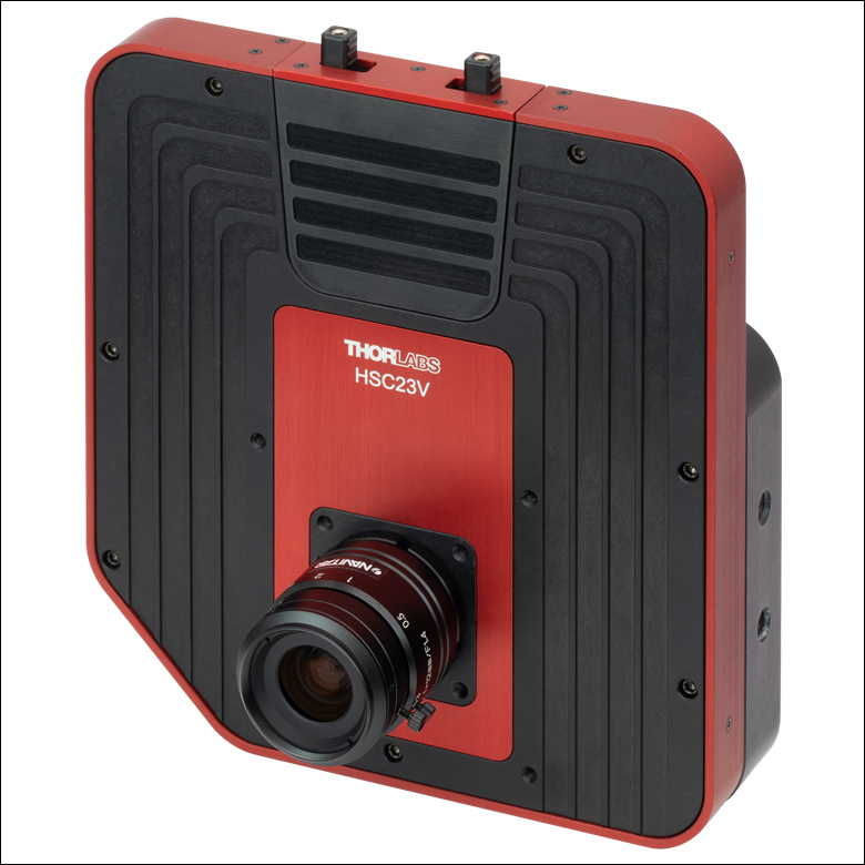 Click to Enlarge Figure 5.2 Our multispectral imaging system with an MVL12M1 Machine Vision Lens installed. |
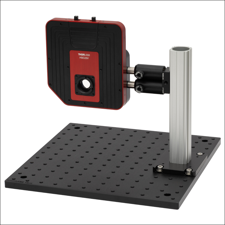 Click to Enlarge Figure 5.3 The pairs of 1/4"-20 tapped holes on the bottom and side of the imaging system can be used to provide repeatable positioning and protect against rotation of the imaging system while mounted. |
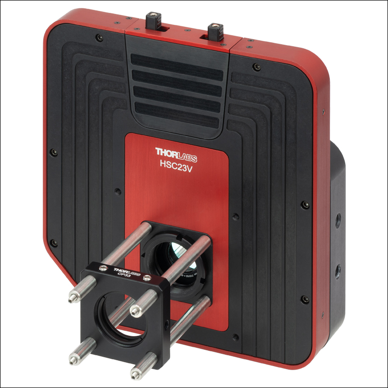 Click to Enlarge Figure 5.4 Four 4-40 tapped holes allow 30 mm Cage System components to be attached to the imaging system. Pictured is our CP33 Cage Plate with SM1 threading. |
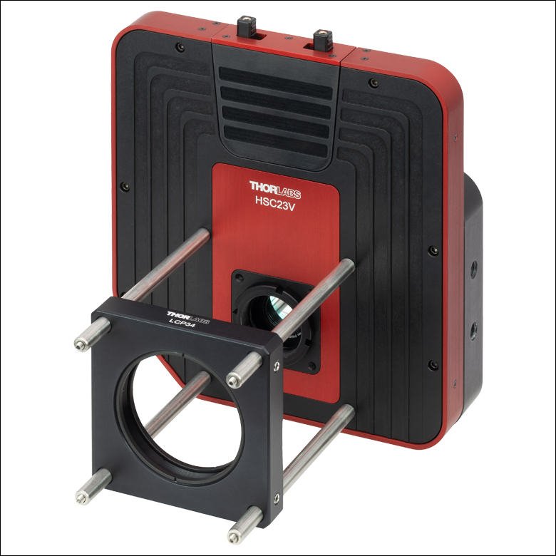 Click to Enlarge Figure 5.5 Four 4-40 tapped holes allow 60 mm Cage System components to be attached to the imaging system. Pictured is our LCP34 Cage Plate with SM2 threading. |
Software
Version 1.0.0
Click the button to visit the Multispectral Imaging System software page.
| Table 6.1 Minimum Requirements | |
|---|---|
| Operating System | Windows® 10 or Windows 11 |
| Processor (CPU) | Intel Core i5 or AMD Athlon II |
| Memory (RAM) | 8 GB |
| Hard Drive | 2 GB of Available Disk Space |
| Interface | Free High-Speed USB 3.0 Port |
The HSC23V Multispectral Imaging System software allows a user to view a Live output from the camera, capture individual images from a single filter (Single), and capture all filters in the wheel (Full Stack). Please refer to the software manual on the software page for further details on how to use these functions.
Click to Enlarge
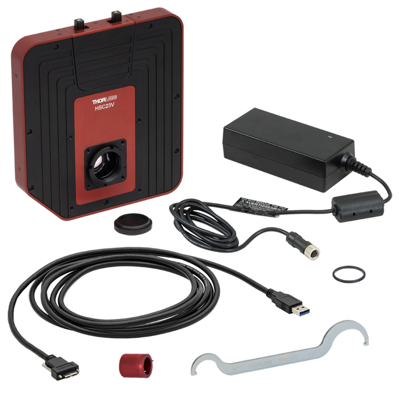
Figure 7.1 The HSC23V Multispectral Imaging System is shipped with the components shown above.
The HSC23V multispectral imaging system ships with the following components:
- HSC23V Multispectral Imaging System
- HSCFWB Filter Wheel (Mounted Inside the Multispectral Imaging System)
- DS12 Power Supply with Region Specific Power Adapter
- CABU31 USB 3.1 Type Type-A to Micro B Cable, Locking Screws, 3 m (118") Long
- SPW502 Spanner Wrench for C-Mount Adapter
- SPW909 Spanner Wrench for HSC Series Filters and Hub Nut
- SM1RR Retaining Ring

Insights into Mounting Lenses to Thorlabs' Scientific Cameras
Scroll down to read about compatibility between lenses and cameras of different mount types, with a focus on Thorlabs' scientific cameras.
- Can C-mount and CS-mount cameras and lenses be used with each other?
- Do Thorlabs' scientific cameras need an adapter?
- Why can the FFD be smaller than the distance separating the camera's flange and sensor?
Click here for more insights into lab practices and equipment.
Can C-mount and CS-mount cameras and lenses be used with each other?
Click to Enlarge
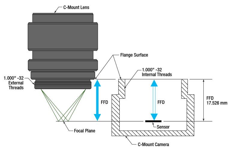
Figure 194A C-mount lenses and cameras have the same flange focal distance (FFD), 17.526 mm. This ensures light through the lens focuses on the camera's sensor. Both components have 1.000"-32 threads, sometimes referred to as "C-mount threads".
Click to Enlarge
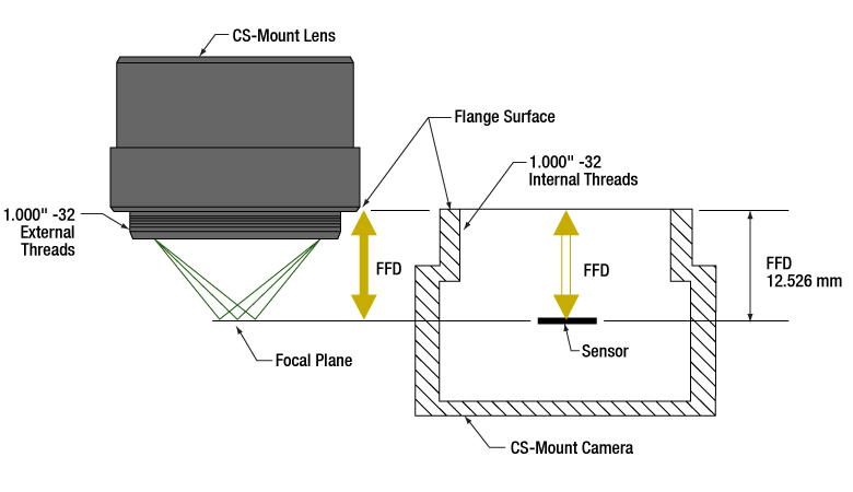
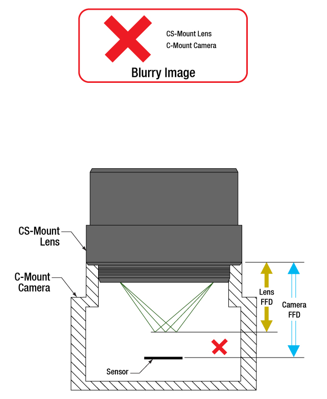
Figure 194B CS-mount lenses and cameras have the same flange focal distance (FFD), 12.526 mm. This ensures light through the lens focuses on the camera's sensor. Their 1.000"-32 threads are identical to threads on C-mount components, sometimes referred to as "C-mount threads."
The C-mount and CS-mount camera system standards both include 1.000"-32 threads, but the two mount types have different flange focal distances (FFD, also known as flange focal depth, flange focal length, register, flange back distance, and flange-to-film distance). The FFD is 17.526 mm for the C-mount and 12.526 mm for the CS-mount (Figures 194A and 194B, respectively).
Since their flange focal distances are different, the C-mount and CS-mount components are not directly interchangeable. However, with an adapter, it is possible to use a
Mixing and Matching
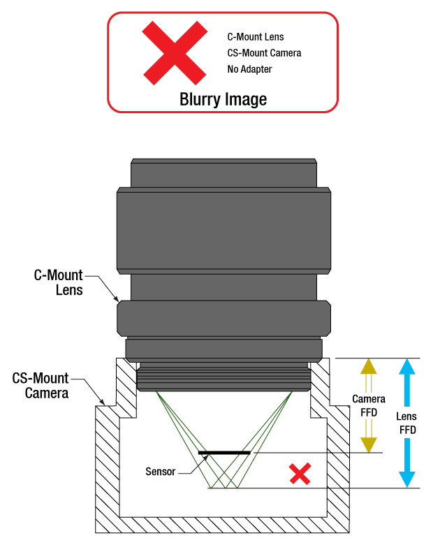
C-mount and CS-mount components have identical threads, but lenses and cameras of different mount types should not be directly attached to one another. If this is done, the lens' focal plane will not coincide with the camera's sensor plane due to the difference in FFD, and the image will be blurry.
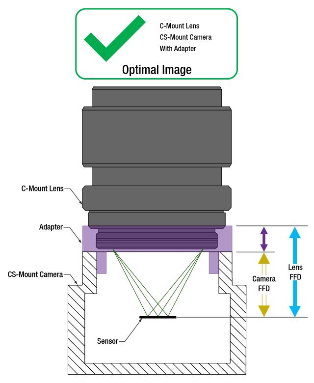
With an adapter, a C-mount lens can be used with a CS-mount camera (Figures 194C and 194D). The adapter increases the separation between the lens and the camera's sensor by 5.0 mm, to ensure the lens' focal plane aligns with the camera's sensor plane.
In contrast, the shorter FFD of CS-mount lenses makes them incompatible for use with C-mount cameras (Figure 194E). The lens and camera housings prevent the lens from mounting close enough to the camera sensor to provide an in-focus image, and no adapter can bring the lens closer.
It is critical to check the lens and camera parameters to determine whether the components are compatible, an adapter is required, or the components cannot be made compatible.
1.000"-32 Threads
Imperial threads are properly described by their diameter and the number of threads per inch (TPI). In the case of both these mounts, the thread diameter is 1.000" and the TPI is 32. Due to the prevalence of C-mount devices, the 1.000"-32 thread is sometimes referred to as a "C-mount thread." Using this term can cause confusion, since CS-mount devices have the same threads.
Measuring Flange Focal Distance
Measurements of flange focal distance are given for both lenses and cameras. In the case of lenses, the FFD is measured from the lens' flange surface (Figures 194A and 194B) to its focal plane. The flange surface follows the lens' planar back face and intersects the base of the external 1.000"-32 threads. In cameras, the FFD is measured from the camera's front face to the sensor plane. When the lens is mounted on the camera without an adapter, the flange surfaces on the camera front face and lens back face are brought into contact.
Click to Enlarge
Figure 194E A CS-mount lens is not directly compatible with a C-mount camera, since the light focuses before the camera's sensor. Adapters are not useful, since the solution would require shrinking the flange focal distance of the camera (blue arrow).
Click to Enlarge
Figure 194D An adapter with the proper thickness moves the C-mount lens away from the CS-mount camera's sensor by an optimal amount, which is indicated by the length of the purple arrow. This allows the lens to focus light on the camera's sensor, despite the difference in FFD.
Click to Enlarge
Figure 194C A C-mount lens and a CS-mount camera are not directly compatible, since their flange focal distances, indicated by the blue and yellow arrows, respectively, are different. This arrangement will result in blurry images, since the light will not focus on the camera's sensor.
Date of Last Edit: July 21, 2020
Do Thorlabs' scientific cameras need an adapter?
Click to Enlarge
Figure 194F An adapter can be used to optimally position a C-mount lens on a camera whose flange focal distance is less than 17.526 mm. This sketch is based on a Zelux camera and its SM1A10Z adapter.
Click to Enlarge
Figure 194G An adapter can be used to optimally position a CS-mount lens on a camera whose flange focal distance is less than 12.526 mm. This sketch is based on a Zelux camera and its SM1A10 adapter.
All Kiralux™ and Quantalux® scientific cameras are factory set to accept C-mount lenses. When the attached C-mount adapters are removed from the passively cooled cameras, the
The SM1 threads integrated into the camera housings are intended to facilitate the use of lens assemblies created from Thorlabs components. Adapters can also be used to convert from the camera's C-mount configurations. When designing an application-specific lens assembly or considering the use of an adapter not specifically designed for the camera, it is important to ensure that the flange focal distances (FFD) of the camera and lens match, as well as that the camera's sensor size accommodates the desired field of view (FOV).
Made for Each Other: Cameras and Their Adapters
Fixed adapters are available to configure the Zelux cameras to meet C-mount and CS-mount standards (Figures 194F and 194G). These adapters, as well as the adjustable C-mount adapters attached to the passively cooled Kiralux and Quantalux cameras, were designed specifically for use with their respective cameras.
While any adapter converting from SM1 to
The position of the lens' focal plane is determined by a combination of the lens' FFD, which is measured in air, and any refractive elements between the lens and the camera's sensor. When light focused by the lens passes through a refractive element, instead of just travelling through air, the physical focal plane is shifted to longer distances by an amount that can be calculated. The adapter must add enough separation to compensate for both the camera's FFD, when it is too short, and the focal shift caused by any windows or filters inserted between the lens and sensor.
Flexiblity and Quick Fixes: Adjustable C-Mount Adapter
Passively cooled Kiralux and Quantalux cameras consist of a camera with SM1 internal threads, a window or filter covering the sensor and secured by a retaining ring, and an adjustable C-mount adapter.
A benefit of the adjustable C-mount adapter is that it can tune the spacing between the lens and camera over a 1.8 mm range, when the window / filter and retaining ring are in place. Changing the spacing can compensate for different effects that otherwise misalign the camera's sensor plane and the lens' focal plane. These effects include material expansion and contraction due to temperature changes, positioning errors from tolerance stacking, and focal shifts caused by a substitute window or filter with a different thickness or refractive index.
Adjusting the camera's adapter may be necessary to obtain sharp images of objects at infinity. When an object is at infinity, the incoming rays are parallel, and location of the focus defines the FFD of the lens. Since the actual FFDs of lenses and cameras may not match their intended FFDs, the focal plane for objects at infinity may be shifted from the sensor plane, resulting in a blurry image.
If it is impossible to get a sharp image of objects at infinity, despite tuning the lens focus, try adjusting the camera's adapter. This can compensate for shifts due to tolerance and environmental effects and bring the image into focus.
Date of Last Edit: Aug. 2, 2020
Why can the FFD be smaller than the distance separating the camera's flange and sensor?
Click to Enlarge
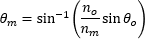
Figure 194J Refraction causes the ray's angle with the optical axis to be shallower in the medium than in air (θm vs. θo ), due to the differences in refractive indices (nm vs. no ). After travelling a distance d in the medium, the ray is only hm closer to the axis. Due to this, the ray intersects the axis Δf beyond the f point.;

Click to Enlarge
Figure 194H A ray travelling through air intersects the optical axis at point f. The ray is ho closer to the axis after it travels across distance d. The refractive index of the air is no .
| Table 194L Example of Calculating Focal Shift | |||
|---|---|---|---|
| Known Information | |||
| C-Mount FFD | f | 17.526 mm | |
| Total Glass Thickness | d | ~1.6 mm | |
| Refractive Index of Air | no | 1 | |
| Refractive Index of Glass | nm | 1.5 | |
| Lens f-Number | f / N | f / 1.4 | |
| Parameter to Calculate |
Exact Equations | Paraxial Approximation |
|
| θo | 20° | ||
| ho | 0.57 mm | --- | |
| θm | 13° | --- | |
| hm | 0.37 mm | --- | |
| Δf | 0.57 mm | 0.53 mm | |
| f + Δf | 18.1 mm | 18.1 mm | |
| Table 194K Equations for Calculating the Focal Shift (Δf ) | ||
|---|---|---|
| Angle of Ray in Air, from Lens f-Number ( f / N ) |  |
|
| Change in Distance to Axis, Travelling through Air (Figure 194H) |  |
|
| Angle of Ray to Axis, in the Medium (Figure 194J) |
 |
|
| Change in Distance to Axis, Travelling through Optic (Figure 194J) |  |
|
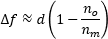
| Focal Shift Caused by Refraction through Medium (Figure 194J) | Exact Calculation |
 |
| Paraxial Approximation |
 |
|
Click to Enlarge
Figure 194N Tolerance and / or temperature effects may result in the lens and camera having different FFDs. If the FFD of the lens is shorter, images of objects at infinity will be excluded from the focal range. Since the system cannot focus on them, they will be blurry.
Click to Enlarge
Figure 194M When their flange focal distances (FFD) are the same, the camera's sensor plane and the lens' focal plane are perfectly aligned. Images of objects at infinity coincide with one limit of the system's focal range.
Flange focal distance (FFD) values for cameras and lenses assume only air fills the space between the lens and the camera's sensor plane. If windows and / or filters are inserted between the lens and camera sensor, it may be necessary to increase the distance separating the camera's flange and sensor planes to a value beyond the specified FFD. A span equal to the FFD may be too short, because refraction through windows and filters bends the light's path and shifts the focal plane farther away.
If making changes to the optics between the lens and camera sensor, the resulting focal plane shift should be calculated to determine whether the separation between lens and camera should be adjusted to maintain good alignment. Note that good alignment is necessary for, but cannot guarantee, an in-focus image, since new optics may introduce aberrations and other effects resulting in unacceptable image quality.
A Case of the Bends: Focal Shift Due to Refraction
While travelling through a solid medium, a ray's path is straight (Figure 194H). Its angle
When an optic with plane-parallel sides and a higher refractive index
While travelling through the optic, the ray approaches the optical axis at a slower rate than a ray travelling the same distance in air. After exiting the optic, the ray's angle with the axis is again θo , the same as a ray that did not pass through the optic. However, the ray exits the optic farther away from the axis than if it had never passed through it. Since the ray refracted by the optic is farther away, it crosses the axis at a point shifted Δf beyond the other ray's crossing. Increasing the optic's thickness widens the separation between the two rays, which increases Δf.
To Infinity and Beyond
It is important to many applications that the camera system be capable of capturing high-quality images of objects at infinity. Rays from these objects are parallel and focused to a point closer to the lens than rays from closer objects (Figure 194J). The FFDs of cameras and lenses are defined so the focal point of rays from infinitely distant objects will align with the camera's sensor plane. When a lens has an adjustable focal range, objects at infinity are in focus at one end of the range and closer objects are in focus at the other.
Different effects, including temperature changes and tolerance stacking, can result in the lens and / or camera not exactly meeting the FFD specification. When the lens' actual FFD is shorter than the camera's, the camera system can no longer obtain sharp images of objects at infinity (Figure 194N). This offset can also result if an optic is removed from between the lens and camera sensor.
An approach some lenses use to compensate for this is to allow the user to vary the lens focus to points "beyond" infinity. This does not refer to a physical distance, it just allows the lens to push its focal plane farther away. Thorlabs' Kiralux™ and Quantalux® cameras include adjustable C-mount adapters to allow the spacing to be tuned as needed.
If the lens' FFD is larger than the camera's, images of objects at infinity fall within the system's focal range, but some closer objects that should be within this range will be excluded. This situation can be caused by inserting optics between the lens and camera sensor. If objects at infinity can still be imaged, this can often be acceptable.
Not Just Theory: Camera Design Example
The C-mount, hermetically sealed, and TE-cooled Quantalux camera has a fixed 18.1 mm spacing between its flange surface and sensor plane. However, the FFD (f ) for C-mount camera systems is 17.526 mm. The camera's need for greater spacing becomes apparent when the focal shift due to the window soldered into the hermetic cover and the glass covering the sensor are taken into account. The results recorded in Table 194L show that both exact and paraxial equations return a required total spacing of 18.1 mm.
Date of Last Edit: July 31, 2020
| Posted Comments: | |
| No Comments Posted |

 Zoom
ZoomClick to Enlarge
Figure G1.1 Our multispectral imaging system with an MVL12M1 Machine Vision Lens installed.
- Max Frame Rate: 40 fps (Full Sensor)
- Compatible with 30 mm and 60 mm Cage Systems
- SM1-Threaded (1.035"-40) Aperture with Adapter for Standard C-Mount (1.000"-32) Compatibility
The HSC23V multispectral imaging system features a 1/1.2" format, monochrome CMOS 2.3 MP sensor. The global shutter of the imaging system scans the entire field of view simultaneously, allowing for the imaging of fast-moving objects. A C-mount (1.000"-32) adapter is included for compatibility with many machine vision camera lenses and C-mount extension tubes. A replacement C-Mount adapter, SM1A10A, is available separately. Removing this adapter exposes SM1 (1.035"-40) threading that can be used to attach a Ø1" Lens Tube or SM1-Threaded Adapter. Please note that dust and debris may collect on the sensor face plate while the clear window is removed. Care must be taken when cleaning this face plate to avoid damaging the sensor.
Thorlabs’ HSC23V multispectral imaging system features a 12-slot filter wheel, that allows customers to tailor their system to their own application. The filter wheel can be removed to replace filters mounted in the wheel. For that, the filter hatch needs to be removed from the system and the front panel of the imaging system needs to be taken off. Then, the filter wheel can be removed, using the provided SPW909 spanner wrench to remove the lock nut for the hub of the wheel. Further information on filter replacement can be found in the imaging system manual. Filter kits are sold separately as sets of twelve (12) filters for various wavelength ranges (VIS, VIS/NIR, or NIR), as well as various full width at half maximum (FWHM) bandwidths. An extra HSCFWB empty filter wheel may be purchased to make swapping between filter sets easier.
The imaging system can be attached directly to our 30 mm and 60 mm cage systems via the 4-40 mounting holes on the front of the housing. Four 1/4"-20 tapped holes (two on the bottom with a spacing of 2", two on the side with a spacing of 1") on the housing provide compatibility with imperial Ø1/2" Posts, Ø1" Posts, and many standard tripod mounts. For more information about mounting the HSC23V imaging system, see the Mounting Options tab.
Click to Enlarge
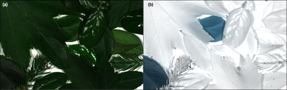
Figure G1.2 Images of foliage using the HSC23V Multispectral Imaging System with 3 different filters to generate an RGB image (a) and the HSC23V Multispectral Imaging System with an 800 nm filter (b). The left image (a) shows the leaves in RGB, where the artificial leaves are indistinguishable from natural leaves, while in the image on the right (b) the artificial leaves can be clearly distinguished (shown in blue).

 Zoom
ZoomAdditional HSCFWB filter wheels are available to make swapping between sets easier, allowing users to capture multispectral images using a wider variety of Thorlabs bandpass filters. The 12-slot wheel can be populated with a pre-configured layout using off-the-shelf filter sets (available separately below) or customized to meet the needs of a user’s particular application.

 Zoom
ZoomThorlabs' Hard-Coated Bandpass Filter Kits contain 12 mounted hard-coated bandpass filters that can be used with the HSC23V Multispectral Imaging System to transmit well-defined wavelength bands in the VIS/NIR or NIR, while rejecting other unwanted radiation. Each filter is mounted in a M20 x 0.6-threaded Ø20.3 mm black-anodized aluminum ring that can be placed into the HSCFWB filter wheel. An extra HSCFWB filter wheel may be purchased separately to make swapping between sets easier. The filter kits come in a convenient plastic box for storage and transportation. Expand Tables G3.1, G3.2, G3.3, and G3.4 for more information on the individual filters contained in each kit.
Note: The dimensions of filters in these kits have been optimized to be compatible with the multispectral imaging system. Other Thorlabs filters are not compatible with the HSC23V Multispectral Imaging System. Only filters from the kits sold here should be used with the imaging system.
| Table G3.1 HSCFW1: VIS/NIR CWLs, 40 nm FWHM |
|---|

| Table G3.2 HSCFW2: VIS/NIR CWLs, 10 nm FWHM |
|---|


| Table G3.3 HSCFW3: VIS CWLs, 10 nm FWHM |
|---|

| Table G3.4 HSCFW4: NIR CWLs, 10 nm FWHM |
|---|
