 Products Home / Actuators, Adjusters, & Transducers / Motorized Actuators / 1/2" (12 mm or 13 mm) Travel Motorized Actuators
1/2" (12 mm or 13 mm) Travel Motorized Actuators
- High-Precision Piezo Inertia Actuators
- Motorized Micrometer-Head Steppers
- Precision DC Servo Motor Actuators
- High-Load Precision Stepper Motor Actuators
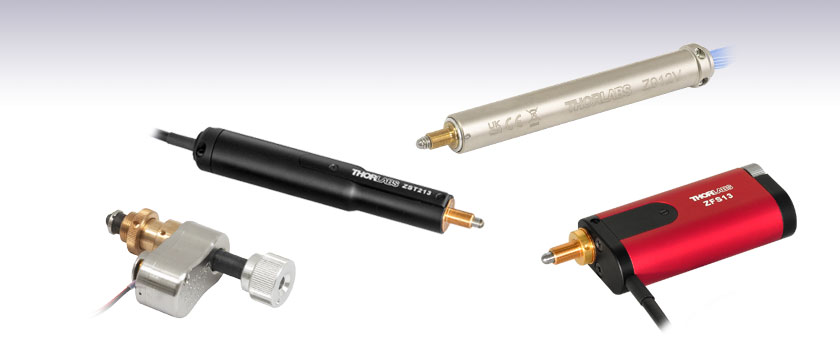
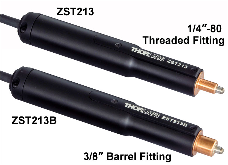
ZST213
13 mm Travel
Stepper Motor Actuator
Z912V
12 mm Travel
DC Motor Actuator
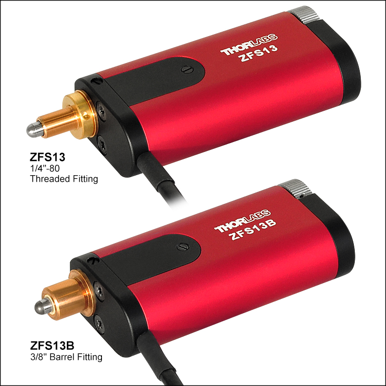
ZFS13
13 mm Travel, Compact
Stepper Motor Actuator
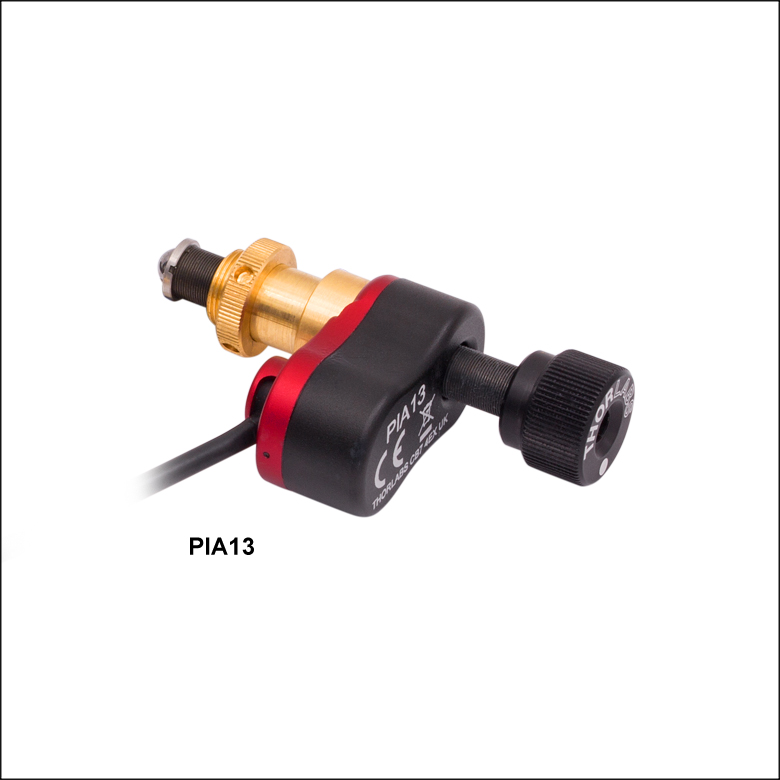
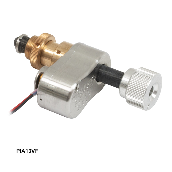
PIA13VF
13 mm Travel
Piezo Inertia Actuator, Vacuum-Compatible


Please Wait
| Table 1.1 Available Models | ||||||||||
|---|---|---|---|---|---|---|---|---|---|---|
| Item #a | Z912 | Z912B | Z912V | Z912BV | ZFS13 | ZFS13B | ZST213 | ZST213B | PIA13 | PIA13VF |
| Travel | 12 mm (0.47") | 13 mm (0.51") | 13 mm (0.51") | |||||||
| Motor Type | DC Servo w/ Encoder | 2-Phase Stepper | Piezo Inertia Acuator | |||||||
| Mounting | 1/4"-80 Thread | Ø3/8" (Ø9.525 mm) Barrel | 1/4"-80 Thread | Ø3/8" (Ø9.525 mm) Barrel | 1/4"-80 Thread | Ø3/8" (Ø9.525 mm) Barrel | 1/4"-80 Thread | Ø3/8" (Ø9.525 mm) Barrel | ||
| Vacuum Rating | N/A | 10-6 Torr | N/A | N/A | 10-6 Torr | |||||
| Required Controller | KDC101 | KST201 | KIM001 or KIM101 | |||||||
Features
- 12 mm or 13 mm (1/2") Travel
- Stepper Motor, Servo Motor, and Piezo Inertia Actuator Models
- Rotating and Non-Rotating Drive Tips
- Replace Micrometers on Manual Stages and Mounts
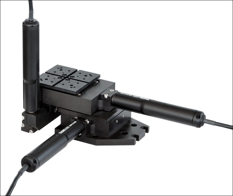
Thorlabs' Motorized Actuators are designed for use with optical positioning devices. They offer high resolution in lightweight packages, which makes these actuators ideally suited for demanding optical automation applications. These 12 mm or 13 mm (1/2") travel motorized actuators are available with three drive types: 2-phase stepper motors, DC servos with encoders, or piezo inertia actuators. Vacuum-compatible models with DC servos or piezo inertia actuators provide functionality down to 10-6 Torr. See Table 1.1 for an overview of the available models.
| Table 1.2 Quick Links to Other Motorized Actuators | |||
|---|---|---|---|
| 10 mm (0.39") or Less Travel | 12 mm or 13 mm (1/2") Travel | 25 mm (1") Travel | 50 mm (2") Travel |
ZFS Series and ZST Series Actuators
Pin Diagram
High-Density D-Type Male 15 Pin Connector
15-Pin D-Sub Connector Pin Out
| Pin | Description | Pin | Description |
|---|---|---|---|
| 1 | Limit Ground | 8 | Reserved for Future Use |
| 2 | CCW Limit Switch | 9 | Reserved for Future Use |
| 3 | CW Limit Switch | 10 | Vcc (+5 VDC) |
| 4 | Motor Phase B - | 11 | Reserved for Future Use |
| 5 | Motor Phase B + | 12 | Reserved for Future Use |
| 6 | Motor Phase A - | 13 | Reserved for Future Use |
| 7 | Motor Phase A + | 14 | Reserved for Future Use |
| - | - | 15 | Ground |
Click to Enlarge
High-Density D-Type Male 15 Pin Connector
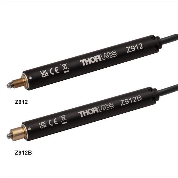
Z912 and Z912B Actuators
Pin Diagram
High-Density D-Type Male 15 Pin Connector
15-Pin D-Sub Connector Pin Out
| Pin | Description | Pin | Description |
|---|---|---|---|
| 1 | Ground (Limit and Vcc) | 9 | Resistive Identification |
| 2 | Forward Limit | 10 | +5 VDC |
| 3 | Reverse Limit | 11 | Encoder Channel A |
| 4 | Reserved for Future Use | 12 | Reserved for Future Use |
| 5 | Motor (-) | 13 | Encoder Channel B |
| 6 | Reserved for Future Use | 14 | Pin 2 Identification EEPROM |
| 7 | Motor (+) | 15 | Pin 1 Identification EEPROM |
| 8 | Reserved for Future Use |
Click to Enlarge
High-Density D-Type Male 15 Pin Connector
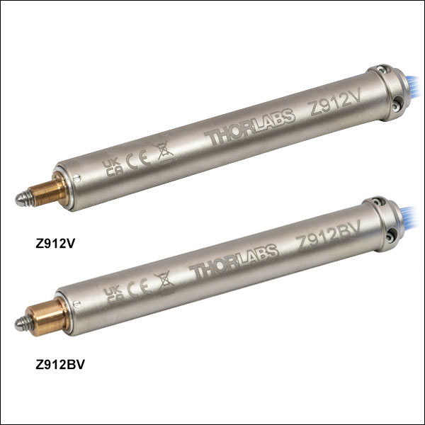
Z912V and Z912BV Actuators
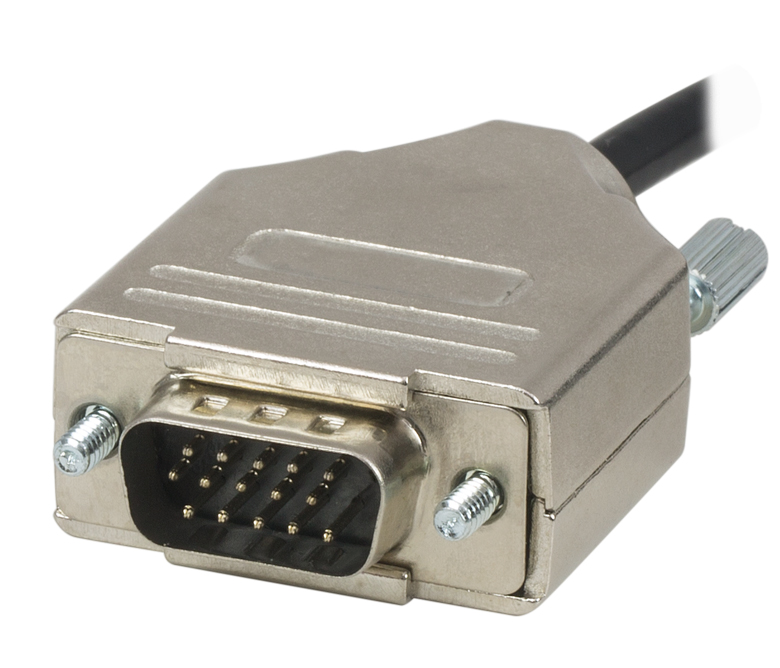
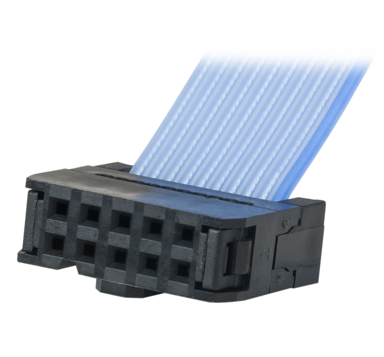
The vacuum-compatible cable integrated with the Z912V and Z912BV actuators is terminated in a female IDC 10-Pin socket connector. A short converter cable, which adapts this female IDC socket connector to a D-type male HD15 pin connector, is included with the Z912V and Z912BV actuators to facilitate connecting it to the recommended KDC101 controller. This converter cable, whose terminating connectors are shown below, is not vacuum compatible. Information describing the pin assignments for both the female IDC socket and male D-type HD connector (when it is connected to the female IDC socket connector) follows.
Pin Diagram
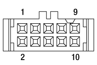
10 Pin Female IDC Socket Connector
(Amphenol T812 Series, 2.54 mm Pitch)
Female IDC 10-Pin Connector Pin Out
| Pin | Description | Pin | Description |
|---|---|---|---|
| 1 | Motor (+) | 6 | Motor (-) |
| 2 | Vcc | 7 | Limit Ground |
| 3 | Channel A | 8 | Reverse Limit |
| 4 | Channel B | 9 | Forward Limit |
| 5 | Ground | 10 | Not Connected |
Pin Diagram
High-Density D-Type Male 15 Pin Connector
Male HDDB15 Connector Pin Out
| Pin | Description | Pin | Description |
|---|---|---|---|
| 1 | Ground (Limit and Vcc) | 8 | Reserved For Future Use |
| 2 | Forward Limit | 9 | Ident Resistor |
| 3 | Reverse Limit | 10 | Vcc (+5 VDC) |
| 4 | Reserved For Future Use | 11 | Encoder Channel A |
| 5 | Motor (-) | 12 | Reserved for Future Use |
| 6 | Reserved for Future Use | 13 | Encoder Channel B |
| 7 | Motor (+) | 14, 15 | Reserved For Future Use |
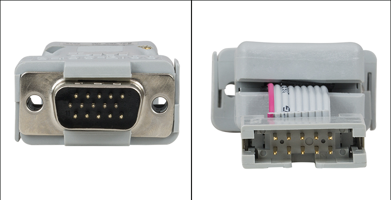
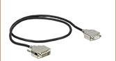
Click to Enlarge
Connectors terminating the converter cable. The image on the left shows the high-density D-type male 15-pin connector, and the image on the right shows the 10-pin male IDC socket connector.
Example: Calculating the Linear Displacement per Microstep for Stepper Motor Driven Actuators
The ZFS series of stepper motor actuators have 24 full steps per revolution. When driven by the KST201 driver, there are 2048 microsteps per full step resulting in 49 152 microsteps per revolution of the motor. The output shaft of the motor goes into a 400:9 (~44.444:1) gear head. This requires the motor to rotate 44.444 times to rotate the 1.0 mm pitch lead screw one revolution, giving a linear displacement of 1.0 mm.
Number of microsteps per lead screw revolution is:
Number of Microsteps x Gearbox Ratio = 49 152 x 44.444 = 2 184 511.5 Microsteps per Lead Screw Revolution.
The theoretical linear displacement of the lead screw per microstep is:
1.0 mm / 2 184 511.5 = 0.46 x 10⁻⁶ mm = 0.46 nm.
Summary of Calculations for Stepper Motor Driven Actuators
| Item # | Required Driver | Full Steps per Revolution | Microsteps per Revolution | Gearbox Ratio | Displacement per Microstepa |
|---|---|---|---|---|---|
| ZFS13 | KST201 | 24 | 49 152 | 44.444:1 | 0.46 nm |
| ZFS13B | |||||
| ZST213 | 40.866:1 | 0.50 nm | |||
| ZST213B |
Example: Calculating the Encoder Resoution for Z9 Series Servo Motor Driven Actuators
The Z9 series of servo motor driven actuators have 512 encoder counts per revolution of the servo motor. The output shaft of the motor goes into a 67.49:1 planetary gear head, requiring the motor to rotate 67.49 times to rotate the 1.0 mm pitch lead screw one revolution, giving a linear displacement of 1.0 mm.
The number of encoder counts per lead screw revolution is:
Number of Encoder Counts x Gearbox Ratio = 512 x 67.49 = 34 555 Encoder Counts per Lead Screw Revolution.
The theoretical encoder resolution (linear displacement of the lead screw per encoder count) is:
1.0 mm / 34 555 counts = 2.9 x 10⁻⁵ mm = 29 nm.
Summary of Calculations for Servo Motor Driven Actuators
| Item # | Required Driver | Encoder Counts per Revolution | Gearbox Ratio | Encoder Resolution |
|---|---|---|---|---|
| Z912 | KDC101 | 512 | 67.49:1 | 29 nm |
| Z912B | ||||
| Z912V | ||||
| Z912BV |
| Posted Comments: | |
Hyungchul Park
(posted 2025-06-23 17:03:23.32) Hello my name is Hyungchul Park from Seoul National University. I am using Z912V with a KCube DC Motor controller.
When I switch on the motor the message
1) Unknown stage appears
2) At FWD Limit message appears.
And I cannot move the stage at all.
I originally had the problem that position Home is at the location where moving is blocked by the kinematic stage and to resolve it I hit the "reset stage to factory default " button. Can it be the cause of this behavior? cstroud
(posted 2025-06-24 05:33:41.0) Thanks for reaching out. I'm sorry that you're having issues with your controller, I will contact you directly to help troubleshoot this. Aristeidis Stathis
(posted 2025-06-12 07:46:59.98) Hello.
I am writing to inquire about the compatibility of the following 12 mm travel DC servo motor actuators with your KM200T kinematic mount:
Z912 – 12 mm Travel, DC Servo Motor Actuator, 1/4"-80 Mounting Thread
Z912B – 12 mm Travel, DC Servo Motor Actuator, Ø3/8" Mounting Barrel
Specifically, we are looking to mount a large fiber collimator (C80APC-C) in the KM200T and include the entire setup in a closed-loop pointing, acquisition, and tracking (PAT) system. Could you please confirm whether either of these actuators is suitable for integration with the KM200T in this context? Additionally, we would appreciate any recommendations or considerations regarding actuator choice, precision, or stability for this application. We are open to discussing custom solutions, if available. spolineni
(posted 2025-06-19 11:42:50.0) Thank you for your inquiry.I will reach out to you directly to discuss your application and provide a customized solution to meet your requirements. Jibin S S
(posted 2025-02-10 04:04:52.963) Hello. I have PIA13 and KIM101. I wonder if PIA13 has position sensing and feedback control. If so, how can I make it operational? spolineni
(posted 2025-02-19 09:26:59.0) Thank you for reaching out. The PIA13 is a Piezo Inertia Actuator designed for open-loop motion control and does not have built-in position sensing or feedback control. It operates solely on step commands. I will personally contact you to further discuss and assist with your application. user
(posted 2024-09-26 12:01:22.587) Hi, is there a way to mount the PIA13 piezo inertia actuator to the MBT616D/M 3-Axis MicroBlock stage in place of one of its original actuators? I would be interested to motorize the vertical movement of the MicroBlock. dnewnham
(posted 2024-10-04 11:08:23.0) Thank you for your inquiry, we do not recommend removing the drivers from the MBT616D/M stage so I would not recommend attempting to mount PIA13's to the MBT616D/M stage however I will reach out to you directly to discuss possible alternatives. Andrew Chew
(posted 2024-09-16 11:42:15.06) Hi, is the IDC to D type converter cable offered separately? I might have lost one of them. Thanks. cstroud
(posted 2024-09-19 06:05:34.0) Thanks for reaching out. I will contact you directly to discuss this further. R N
(posted 2024-08-01 10:00:57.507) I am working in device units for position (controlling Z912 with KDC101). For position, the conversion between device units and real units (mm) is clear: 34555 device units is 1.0 mm, and device units are the same as the encoder counts.
How do I convert between device units and real units for velocity and acceleration (real units: mm/s, mm/s^2)? Can you include those device unit conversions in the manual or specifications to make it easier for people to use device units? dnewnham
(posted 2024-08-08 04:36:24.0) Thank you for your feedback. To convert device units to real units for velocity the scaling factor is 772981.3692 (mm/s) and for converting from device units to real units for acceleration the scaling factor is 263.8443072 (mm/s^2). I will reach out to you to discuss this further. Dan Popovic
(posted 2024-07-31 14:12:52.76) We are considering controlling the 12mm Travel DC Servo Motor Actuators with a Beckhoff PLC.
Would it be possible to get full motor specs, at least the maximum/nominal voltage and current?
Thank you spolineni
(posted 2024-08-07 09:13:38.0) Thank you for reaching out to us. I will personally contact you soon to discuss your application and provide any assistance you may need. 舟 李
(posted 2022-11-09 03:04:43.07) I intend to use this product to drive a translation stage with a prism on it to reflect the light beam and adjust the time delay. However, I find the reflected beam suffer seriously from zigzag effect. The beam spot moves up and down periodically as the actuator extends or retracts. I wish to know how to deal with this problem.
我打算用这个产品驱动一个位移台,位移台上面有一个棱镜,用来反射光束和调整延时。然而,我发现反射光受位移台移动影响显著。当促动器伸缩时,光斑周期性地上下抖动。我想知道如何处理这个问题。 cdolbashian
(posted 2022-11-16 11:43:03.0) Thank you for your inquiry. PRC techsupport team have got in touch with you for further information to resolve your issue. chengyun hong
(posted 2022-08-05 20:38:59.843) hello
we have the ZFS13B and the KST 101 in our lab, and we fixed this on the mirror mount to control the beam position in the 50X microscope.
We tried to use the jogging mode and change the beam position in ~0.5 um scale in OM but we find one problem that the jogging is not always working both for kinesis and APT software. It will stop for the first three clicks and after the fourth click, it will move. how can we fix this problem? I think the resolution of the stepper motor is much better than our demand. And I also want to ask how can we make more precise control of the stepper motor. what kinds of parameters we should change to make each step size the same? thank you so much! DJayasuriya
(posted 2022-08-09 08:41:43.0) Thank you for your inquiry. We have got in touch with you directly to resolve your issue chengyun hong
(posted 2022-05-20 18:01:39.78) Dear
I am chengyun Hong in SKKU. Korea Ji-Hee Kim lab.
In our lab we have ZFS13 and I tried to use the KST 101 to control it. And I downloaded the kinesis software but i faced the problem in rectify the ZFS13 in the kinesis software and can not change the defalt setting, which is HS ZST6. when i tried to add the custome setting, all step motter are locked and when i click hte ZFS13, and click creat, it will automatically change back to HS ZST6. Could you please tell us how to connect the ZFS13 with kinesis software? thank you so much! DJayasuriya
(posted 2022-05-20 10:17:44.0) Thank you for your feedback. We have reached out to you directly to resolve your issue. Chengyun Hong
(posted 2022-04-06 14:09:15.0) Hello
I am chengyun hong from the Sungkyunkwan University, Korea.
We have two ZFS13 motorized mirror mount in our lab and now want to use it on the vertical mirror mount(1 inch mirror) to control the beam under OM.
But did not find any suitable vertical mirror mount for it. I think vertical mirror mount which can fix with 1/4"-80 Threaded Bushings is good to use the ZFS13, can we customize it?
Thank you so much DJayasuriya
(posted 2022-04-08 09:26:26.0) Thank you for your inquiry. We have got in touch with you directly to discuss your application and set up. Michael Hadmack
(posted 2021-10-19 19:11:18.667) The limit switch circuit in the manual looks incorrect. It states that pullup resistors to 5V are needed for a 3rd party controller which suggests that the limit switch outputs are open-collector. However, in reality the limit switch outputs are at 5V without an external pullup and the motor appears to have 10kohm pullups internally. This is not how it is described in the manual. What is the actual equivalent circuit for the limit switched? DJayasuriya
(posted 2021-10-27 08:37:33.0) Thank you for your inquiery. This uses a hall sensor which is a open collector with a 10K pull up actually within the stage. So it is not a push pull output from the ZFS itself. When it hits a limit switch it pulls low, given there is a 5v supply to the hall device. Hope this helps. Feel free to contact your local tech support team if you have any questions. hufangze
(posted 2018-11-28 16:34:01.297) ”由于一系列因素,比如应用条件,压电迟滞,组件差异和轴向负载等,所得的步长会有变化,而且无重复性。如要消除这种变化,需要使用一个外部反馈系统。“请问贵司在此提到的外部反馈系统是什么,能否详细说明一下,不胜感激。 fwilliams
(posted 2017-09-28 13:19:31.24) One last thing: I am running 32-bit APT User for use in a 64-bit environment. It's possible that Thorlabs has not updated this version of APT User to include the firmware updates for KST101's. All I can say is that my version (v3.21.1) only includes firmware v1.0.2 for the KST101.
At any rate, there is nothing more I can do here to alleviate the problem. As it is, the hardware fails to perform according to its own published specifications and is therefore unusable by me, at least in its current state. fwilliams
(posted 2017-09-28 08:02:29.833) Sorry, I should've included the fact that I am already using the most-recent version of APT User (v3.21.1). Nonetheless, when I flash the firmware to the KST101, the firmware utility reports that the firmware revision level is v1.0.2, NOT v1.0.6. tfrisch
(posted 2017-10-02 07:19:46.0) Hello, we will reach out to you through your open ticket to discuss this. fwilliams
(posted 2017-09-26 15:30:53.1) FOLLOWUP: Using the firmware-update utility found in the APT User program folder, I determined that my KST101's are running firmware v1.0.2. However, in the APT User change log, the latest firmware for the KST101 is listed as v1.06, which includes the description: "Fixed bug to respond correctly when MoveStop commands are completed." It seems that I need this firmware update - how can I obtain it? bwood
(posted 2017-09-28 08:10:31.0) Response from Ben at Thorlabs: Thank you for your feedback. You can update the firmware of your KST101 with the Firmware Update Utility which is installed with APT. It should be found next to APT on your computer. I would recommend making sure you are using the newest version of APT, when you update the firmware. fwilliams
(posted 2017-09-26 14:32:19.267) Now that I am using the ZST213 in my new system, I find that it drifts much more than the old ZST13 did. The ZST213 is less precise, and struggles at making small jogs (unlike the older actuator, which delivers repeatable and deterministic jogs of 75 nm all day). I am able to make a direct comparison between the two actuators, because I have an older system on the same bench that is identical except for the fact that it uses ZST13's instead of the newer ZST213. If I try to make a jog of 75 nm (say) with the ZST213, I often see no movement (other than an uncorrelated random drift). If I keep sending Jog commands, all of a sudden the system will move a significant distance, slowly coming to a stop. I have tried playing with the Jog settings (velocity, accn, immediate vs. profiles stopping, etc.), but nothing seems to improve the situation. I am using KST101 cubes to control the ZST213's. Is there a firmware fix for this problem? bwood
(posted 2017-09-28 08:20:26.0) Please find my response above. fwilliams
(posted 2017-06-28 11:08:39.82) Never mind - I figured out my problem. I had the wrong setting for the lead-screw pitch. I was using 0.5 mm (the pitch of the now-obsolete ZST13B) instead of the correct value of 1.0 mm for the ZST213B.
When I said in my earlier post that I use APT User, I actually run it from within a Matlab program that calls APT User. I developed this program with the old ZST13B. I'm now setting up a new system using this Matlab program, and had neglected to update the settings for the newer actuator.
Sorry about the confusion. tfrisch
(posted 2017-07-01 11:40:20.0) Hello, thank you for this followup. I'm glad you were able to find a solution, please let us know if you need anything further. fwilliams
(posted 2017-06-27 14:48:18.903) I am running a ZST213B with a KST101 controller, using the APT User interface. I am finding that the motion is completely uncalibrated. For example, after homing to zero, entering a command to move to 6 mm (say) will cause the actuator to move the full length of travel (i.e., ~ 13 mm). The only way I can get the actuator to move an approximately correct distance is to adjust down the Gearbox Ratio to something like 19 (it should be 41).
Just so there's no question, I ran APT Config before running the actuator with APT User, making sure to choose the proper stage designation ["ZST213(B)"] when I associated the stage with the controller's serial number.
Is there a way to get the actuator/controller to behave correctly? tfrisch
(posted 2017-07-01 11:40:26.0) Hello, thank you for contacting Thorlabs. I see you were able to find a solution above. Please let us know if you need anything further. user
(posted 2017-04-04 05:46:30.73) Is it possible to convert a Z812B to Z812? By means of a mounting kit maybe bhallewell
(posted 2017-04-04 09:35:33.0) Response from Ben at Thorlabs: This is not possible. You could upgrade a Z812 to hold a 3/8" barrel with F25SSA1 however not the other way around. redwgn67
(posted 2015-07-10 15:07:11.147) Is there an adapter fitting to convert the 1/4"-80 Threaded Barrel to a 3/8" Smooth Barrel? I'd really like to use one of these with either a mirror mount (needs 1/4"-80 threaded) or a translation stage (needs 3/8" smooth), rather than having to buy two. besembeson
(posted 2015-09-23 11:11:12.0) Response from Bweh at Thorlabs USA: We don't have such an adapter at this time. lsandstrom
(posted 2010-02-12 14:06:25.0) What is the minimum bend radius for the cable that is mounted on the Z8? david.moore22
(posted 2009-09-18 16:17:59.0) Does the Z612BV come with the same ribbon connector as the original Z612? Do you provide extension ribbon cables? Thank you. jens
(posted 2009-09-18 16:44:49.0) A reply from Jens at Thorlabs: the Z612BV comes with the same connector. We decided to include the connector even though customers using the product in a vacuum chamber will usually need to cut the connector of in order to connect to the feedthrough. Reason for shipping the item with the connector is that it will allow the end user to easily test the device before implementing it into the setup. The cable itself is a PTFE coated ribbon cable. In order to achieve the best possible performance in a vaccuum chamber I would suggest that we offer a custom actuator with a longer ribbon cable. With this you wont need to use any cable connectors inside the chamber. brian
(posted 2008-04-01 11:18:34.0) Max speed is missing in the spec. I was able to figure it out from the discontinued products above. The link to the BSC103 under the specs tab goes to a different product. Laurie
(posted 2008-04-01 14:10:16.0) Response from Laurie at Thorlabs to brian: The maximum speed for the DRV601 is 2.5 mm/s. Currently, this page is under revision to add new offerings. However, once those new offerings go live, so will changes to the specs tab for this product indicating the maximum speed as well as fixing the broken link that you spotted. Thank you for your interest in our products! |

 Zoom
Zoom| Item # | ZFS13 | ZFS13B |
|---|---|---|
| Mounting Barrel | 1/4"-80 Threaded | Ø3/8" (Ø9.525 mm) Smooth |
| Travel | 13 mm (0.51") | |
| Backlasha | <15.0 µm | |
| Bidirectional Repeatability | <5.0 µm | |
| Home Location Accuracy | <5.0 µm | |
| Maximum Load Capacity | 40 N (8.99 lb) | |
| Velocity | 2.0 mm/s (Max) | |
| Acceleration | 10 mm/s2 (Max) | |
| Gearbox Ratio | 400:9 (Approx. 44:1) | |
| Limit Switches | Hall Effect Sensor | |
| Lead Screw Pitch | 1.0 mm | |
| Motor Type | 2-Phase Stepper | |
| Microsteps per Revolution of the Motorb | 24 Full Steps 2048 Microsteps per Full Step 49 152 Microsteps per Revolution |
|
| Calculated Minimum Incremental Motionc | 0.46 nm | |
| Operating Temperature | 5 to 40 °C (41 to 104 °F) |
|
| Dimensions (W x H) |
35.0 mm x 19.0 mm (0.38" x 0.75") |
|
| Length when Fully Retracted | 89.5 mm (3.52") | 85.5 mm (3.36") |
| Cable Length | 0.6 m (2 ft) | |
| Connector | HDDB15 | |
| Required Controller | KST201 | |
- Compact, Bi-Polar Stepper Motor Actuator:
- ZFS13: 89.5 mm (3.52") Long when Retracted
- ZFS13B: 85.5 mm (3.36") Long when Retracted
- Manual Adjustment via Rear-Located Thumbscrew
- Non-Rotating Drive Tip
- Compatible with Mirror Mounts and Translation Stages using 1/4"-80 Thread (ZFS13) or Ø3/8" (9.525 mm) Mounting Barrel (ZFS13B)
- Also Available in 6 mm and 25 mm Travel Versions
Our ZFS13 and ZFS13B Actuators provide smooth, precise linear motion control in a sleek, compact package measuring just 89.5 mm (3.52") or 85.5 mm (3.36"), respectively, in length when fully retracted. This compact profile reduces the distance between the end of the actuator and optomechanical components, keeping the center of mass closer to the contact point than the ZST actuators.
Powered by a small-diameter, two-phase, bi-polar stepper motor, these actuators operate at speeds of up to 2.0 mm/s. The non-rotating drive tip reduces wear and friction and improves smoothness of motion by removing rotational contact at the tip. If power is not supplied to the actuator, manual adjustment is achievable using the rear-located thumbscrew. The actuator motor can be damaged if this thumbscrew is rotated while power is being supplied.
The ZFS13 actuator has a 1/4"-80 threaded barrel that can be mounted to any manual mirror mount for stage with 1/4"-80 threads, while the ZFS13B actuator has a Ø3/8" (Ø9.525 mm) barrel for compatibility with a wide range of translation and rotation stages. Simply remove the existing manual adjuster from the mount, and screw in our ZFS Actuator.
These actuators incorporate stepper motors that provide sufficient torque for loads up to 40 N. The actuators allow very small step sizes over the entire travel range, delivering greater flexibility with low (<15 µm) backlash and fine resolution. The design incorporates a 400:9 gear reduction head which, when combined with the 49 152 microsteps per revolution offered by the KST201 stepper motor driver, gives a theoretical travel per microstep of 0.46 nm (see the Calculations tab for details).
Hall effect limit switches prevent the unit from being overdriven and provide homing capability with an accuracy of <5.0 μm. The ZFS series actuators come with 0.6 m of cable terminated in a 15-pin D-Type connector (see the Pin Diagrams tab) that is compatible with our KST201 stepper motor controller. A 1 m (3.3 ft) extension cable (PAA614) is available separately.
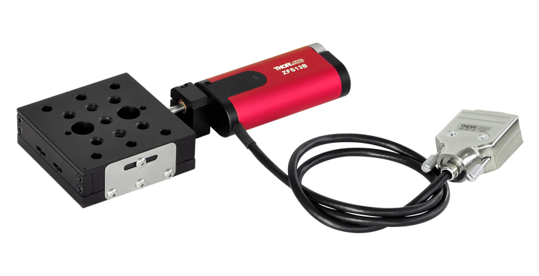
The ZFS13B has a high tolerance standard Ø3/8" (Ø9.525 mm) mounting barrel that is compatible with many translation and rotation stages including our popular MT1 Translation Stages. The ZFS13 has been designed specifically to replace the manual adjusters in stages and mirror mounts that have 1/4"-80 threaded fittings. Simply remove the existing manual adjuster from the mount, and screw in our ZFS Actuator. The manual adjuster of the MT1 stage in Figure G1.1 is replaced with a ZFS13B motorized actuator.

Required Controller:
KST201
- 49 152 Microsteps per Revolution
- 15 V Output at 12 W
- Trapezoidal and
'S-Curve' Velocity Profiles
Click to Enlarge
Figure G1.1 MT1 Stage with Manual Adjuster Replaced by ZFS13B Actuator

 Zoom
Zoom| Item # | ZST213 | ZST213B |
|---|---|---|
| Mounting Barrel | 1/4"-80 Threaded | Ø3/8" (Ø9.525 mm) Smooth |
| Travel | 13 mm (0.51") | |
| Backlasha | <15 µm | |
| Bidirectional Repeatability | <5.0 µm | |
| Home Location Accuracy | <5.0 µm | |
| Maximum Load Capacity | 40 N (8.99 lb) | |
| Velocity | 2.0 mm/s (Max) | |
| Acceleration | 10 mm/s2 (Max) | |
| Gearbox Ratio | 29 791 : 729 (Approx. 41:1) | |
| Limit Switches | Hall Effect Sensor | |
| Lead Screw Pitch | 1.0 mm | |
| Motor Type | 2-Phase Stepper | |
| Microsteps per Revolution of the Motorb | 24 Full Steps 2048 Microsteps per Full Step 49 152 Microsteps per Revolution |
|
| Calculated Minimum Incremental Motion | 0.5 nm | |
| Operating Temperature | 5 to 40 °C (41 to 104 °F) | |
| Cable Length | 0.6 m (2 ft) | |
| Connector | HDDB15 | |
| Required Controller | KST201 | |
- Non-Rotating Drive Tip
- Bi-Polar Stepper Motor Actuator: 123.0 mm (4.84") Long
- Two Mounting Options: Ø3/8" (Ø9.525 mm) Smooth Barrel or 1/4"-80 Threaded Barrel
- Compatible with Mirror Mounts and Translation Stages Using 1/4"-80 Thread or 3/8" (Ø9.525 mm) Mounting Block
- Also Available in 6 mm and 25 mm Travel Versions
Our ZST Actuators provide smooth, precise linear motion control in a package measuring 123.0 mm (4.84") in length. Powered by a small-diameter, two-phase, bi-polar stepper motor, these actuators operate at speeds of up to 2.0 mm/s. The non-rotating drive tip reduces wear and friction and improves smoothness of motion by removing rotational contact at the tip.
These actuators incorporate a stepper motor that provides sufficient torque for loads up to 40 N. They allow very small step sizes over the entire travel range, delivering greater flexibility with low (<15 µm) backlash and fine resolution. The design incorporates a 41:1 gear reduction head which, when combined with the 49 152 microsteps per revolution offered by the KST201 stepper motor driver, gives a theoretical travel per microstep of 0.5 nm (see the Calculations tab for details).
The ZST213 actuator has a 1/4"-80 threaded barrel that can be mounted to any manual mirror mount for stage with 1/4"-80 threads, while the ZT213B actuator has a Ø3/8" (Ø9.525 mm) barrel for compatibility with a wide range of translation and rotation stages, including our popular MT1 Translation Stages. Simply remove the existing manual adjuster from the mount, and screw in our ZST Actuator.
Hall effect limit switches prevent the unit from being overdriven and provide homing capability with an accuracy of <5.0 μm. The ZST series actuators come with 0.6 m (2 ft) of cable terminated in a 15-pin D-Type connector that is compatible with our KST201 stepper motor controller. A 1 m (3.3 ft) extension cable (PAA614) is available separately.
Required Controller:
KST201
- 49 152 Microsteps per Revolution
- 15 V Output at 12 W
- Trapezoidal and
'S-Curve' Velocity Profiles
Click to Enlarge
Figure G2.1 An RB13 3-Axis Stage shown with the manual adjusters replaced by three ZST213B actuators.

 Zoom
Zoom| Item # | Z912 | Z912B |
|---|---|---|
| Mounting Barrel | 1/4"-80 Threaded | Ø3/8" (9.5 mm) Smooth |
| Travel Range | 12 mm (0.47") | |
| Encoder Resolutiona | 34 555 counts/mm (Linear Displacement) |
|
| Maximum Pushing Force | 45 N | |
| Homing Repeatability | ±6 µm | |
| Uncompensated Backlash | 13 µm | |
| Uncompensated Bidirectional Repeatability | ±7 µm | |
| Residual Backlash After Compensationb | 0.7 µm | |
| Compensated Bidirectional Repeatability | ±0.7 µm | |
| Travel Accuracyc | 9 µm | |
| Minimum Repeatable Incremental Movement | 0.2 µm | |
| Maximum Speedd | 2.6 mm/s | |
| Maximum Acceleration | 4 mm/s2 | |
| Maximum Phase to Phase Resistance | 33.0 Ω (Max) | |
| Maximum Phase to Phase Inductance | 0.6 mH (Max) | |
| Tested Lifetimee | >100 000 Cycles | |
| Operating Temperature Range | 41 to 104 °F (5 to 40 °C) |
|
| Weight | 0.13 kg | |
| Motor Typef | DC Servo | |
| Cable Length | 485.0 mm (19.09") | |
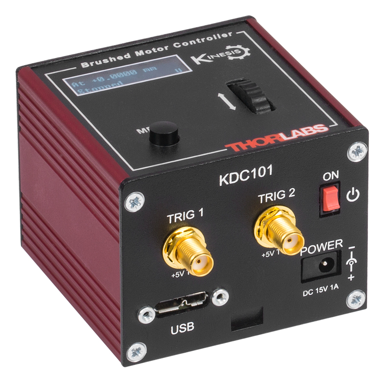
| Required Controller | KDC101 | |
- DC Servo Actuator
- Sub-Micron Resolution
- Maximum Operating Speed: 2.6 mm/s
- Drop-In Replacement for Most 12 mm or 1/2" Manual Actuators
- Compatible with 1/4"-80 Thread or Ø3/8" (Ø9.525 mm) Barrel-Fitted Stages and Mounts
- Limit Switches for Zero Datum and Actuator Protection
- Also Available in 6 mm and 25 mm Travel Versions
Thorlabs' Z912 and Z912B motorized actuators are engineered for use with optical positioning devices. They offer high resolution in a lightweight package, which makes them ideally suited for demanding optical laboratory automation applications.
Electromechanical limit switches provide overdrive protection and accurate home positioning. The incorporated motor is capable of speeds up to 2.6 mm/s, but a maximum speed of 2.3 mm/s is recommended in order to maintain the specified control. The precision of the encoder (512 counts per motor revolution) results in a minimum resolution of about 29 nm. See the Calculations tab for details.
The Z912 has been designed specifically to replace the manual adjusters in stages and mirror mounts that have 1/4"-80 screw-in fittings, while the Z912B is for use with Ø3/8" (Ø9.525 mm) barrel clamps (e.g., the 1/2" manual micrometer in the MT Series Translation Stages). Simply remove the existing manual adjuster from the mount, and screw in our Z9 actuators, as shown in Figure G3.1.
In addition to the Z912 and Z912B motorized actuators, we also offer the Z912V and Z912BV vacuum-compatible versions (see below), which are rated for use down to
The KDC101 DC Servo Controller is the required driver for the Z9 series actuators. The latest version of the Kinesis software and XA software can be downloaded here. When using the Kinesis software package, firmware version 2.2.8 or higher (included with Kinesis software version 1.14.40 or higher) is required to use the KDC101 with the Z9 actuators. Prior versions of firmware will operate the Z9 actuators but will call the actuators Z8.
Required Controller:
KDC101
- 34 555 Encoder Counts per Revolution
- 15 V Output at 2.5 W
- Trapezoidal Velocity Profile

Click to Enlarge
Figure G3.1 A KS2 mirror mount with one screw adjuster replaced with a Z912 actuator.

 Zoom
Zoom| Item # | Z912V | Z912BV |
|---|---|---|
| Mounting Barrel | 1/4"-80 Threaded | Ø3/8" (Ø9.525 mm) Smooth |
| Travel Range | 12 mm (0.47") | |
| Encoder Resolutiona | 34 555 counts/mm (Linear Displacement) |
|
| Maximum Pushing Force | 45 N | |
| Homing Repeatability | ±6 µm | |
| Uncompensated Backlash | 13 µm | |
| Uncompensated Bidirectional Repeatability | ±7 µm | |
| Residual Backlash After Compensationb | 0.7 µm | |
| Compensated Bidirectional Repeatability | ±0.7 µm | |
| Travel Accuracyc | 9 µm | |
| Minimum Repeatable Incremental Movement | 0.2 µm | |
| Maximum Speedd | 2.6 mm/s | |
| Maximum Acceleration | 4 mm/s2 | |
| Maximum Phase to Phase Resistance | 33.0 Ω (Max) | |
| Maximum Phase to Phase Inductance | 0.6 mH (Max) | |
| Tested Lifetimee | >100 000 Cycles | |
| Operating Temperature Range | 41 to 104 °F (5 to 40 °C) |
|
| Vacuum Rating | 10-6 Torr | |
| Weight | 80 g | |
| Motor Typef | DC Servo | |
| Cable Length | 485.0 mm (19.09") | |
| Required Controller | KDC101 | |
- DC Servo Actuator
- Sub-Micron Resolution
- Vacuum Rating: 10-6 Torr
- Maximum Operating Speed: 2.6 mm/s
- Drop-In Replacement for Most 12 mm or 1/2" Manual Actuators
- Compatible with 1/4"-80 Thread or Ø3/8" (Ø9.525 mm) Barrel-Fitted Stages and Mounts
- Limit Switches for Zero Datum and Actuator Protection
- Also Available in 6 mm and 25 mm Travel Versions
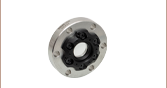
The Z912V and Z912BV actuators offer features and specifications similar to the Z912 actuators described above with the added benefit of being vacuum compatible down to 10-6 Torr. They incorporate vacuum-rated servo motors, a phosphorus bronze internal coupling mechanism and mounting bush, and high-vacuum grease.
These actuators are shipped with a 485.0 mm (19.09") vacuum-compatible flat ribbon cable with an IDC connector. The cable has 1.27 mm (0.05") pitch, 28 AWG stranded conductors, and fluorinated ethylene propylene (FEP) insulation. A converter cable for use with the KDC101 controller is also supplied, but it is not vacuum compatible and should only be used outside the chamber.
For applications with different travel requirements, please see our 6 mm and 25 mm actuators. For vacuum-compatible versions of our stages and mirror mounts, please contact Tech Support.
The KDC101 DC Servo Controller is the required driver for the Z9 series actuators. The latest version of the Kinesis software and XA software can be downloaded here. When using the Kinesis software package, firmware version 2.2.8 or higher (included with Kinesis software version 1.14.40 or higher) is required to use the KDC101 with the Z9 actuators. Prior versions of firmware will operate the Z9 actuators but will call the actuators Z8.
Required Controller:
KDC101
- 34 555 Encoder Counts per Revolution
- 15 V Output at 2.5 W
- Trapezoidal Velocity Profile

 Zoom
Zoom| Item #a | PIA13 | |||
|---|---|---|---|---|
| Travel | 13 mm (0.51") | |||
| Step Sizeb,c | 10 - 30 nm (Typ.) ≤30 nm (Max) |
|||
| Step Size Adjustabilityc | Up to 30% | |||
| Max Step Frequencyd | 2 kHz | |||
| Backlash | None | |||
| Max Active Preloade | 25 N | |||
| Recommended Max Axial Load Capacityf |
2.5 kg (5.5 lbs) | |||
| Speed (Continuous Stepping)b,c | 1.2 - 3.6 mm/min. (Typ.) ≤3.6 mm/min. (Max) |
|||
| Drive Screw | 1/4"-80 Thread, Hard PVD Coated | |||
| Motor Type | Piezoelectric Inertia | |||
| Mounting Feature (Auxiliary) |
Ø3/8" (Ø9.525 mm) Barrel (3/8"-40 Thread with Lock Nut) |
|||
| Operating Temperature | 10 to 40 °C (50 to 104 °F) | |||
| Dimensions | 2.34" x 1.24" x 0.67" (59.5 mm x 31.5 mm x 17.0 mm) |
|||
| Cable Length | 1.0 m (3.28') | |||
| Connector | SMC, Female | |||
| Required Controllerg | KIM001 or KIM101 | |||
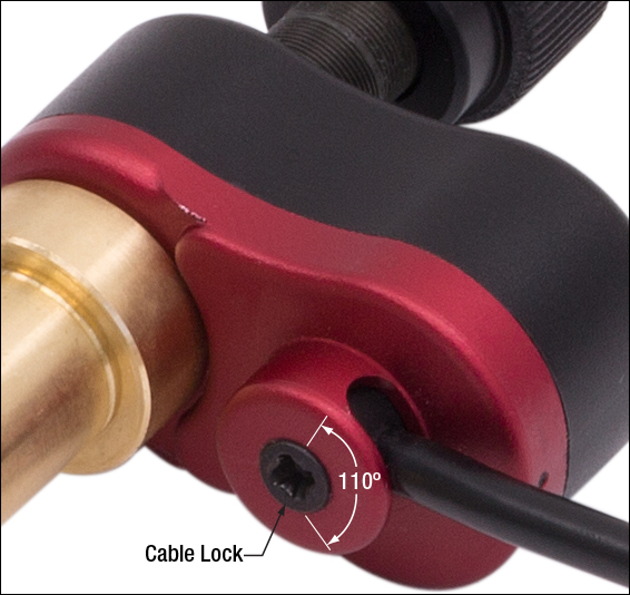
Click for Details
Figure G5.2 The control cable can be adjusted up to 110° for space-constrained applications.
- Ø3/8" (Ø9.525 mm) Mounting Barrel for Compatibility with Translation Stages
- Compact Design: 31.5 mm x 17.0 mm (W x H)
- Manual Adjustment via Knob on Adjuster Screw
- 125 V Maximum Operating Voltage
- Ideal for Set-and-Hold Applications that Require High-Resolution Relative Positioning
- Also Available in 25 mm and 50 mm Travel Versions
Thorlabs' PIA13 Piezoelectric Inertia Actuator provides high-resolution linear motion control with a long piezo-controlled translation range in a compact package. It can support loads up to 2.5 kg and preloads up to 25 N with typical step size ranging from 10 nm to 30 nm with no backlash. The step size can be adjusted up to 30% to a maximum of approximately 30 nm using the KIM101 Controller and Kinesis software. However, due to the open-loop design, piezo hysteresis, and application conditions such as the direction of travel, the achieved step size of the system can vary by up to 20% and is not normally repeatable. An external feedback system will need to be used to overcome this variance.
This actuator has a Ø3/8" (Ø9.525 mm) barrel that can be mounted in a manual stage that has a Ø3/8" (Ø9.525 mm) mounting clamp. For compatibility with 1/4"-80 or 3/16"-100 threaded mirror mounts see our 10 mm travel piezo inertia actuators. The actuator is self-locking when at rest and when there is no power supplied to the piezo, making the actuator ideal for set-and-hold applications that require nanometer resolution and long-term alignment stability. Manual adjustments can be made using the knob on the adjuster screw, as long as the piezo is not actively translating the screw; the knob is also compatible with 5/64" (2.0 mm) hex keys.
Powered by a 10 mm long discrete piezo stack, the actuator can operate at speeds of up to 3.6 mm/minute. The design of the piezo motor will rotate the tip of the lead screw during translation. For information on the design of our piezo inertia "slip-stick" motor actuators, please see the complete presentation here.
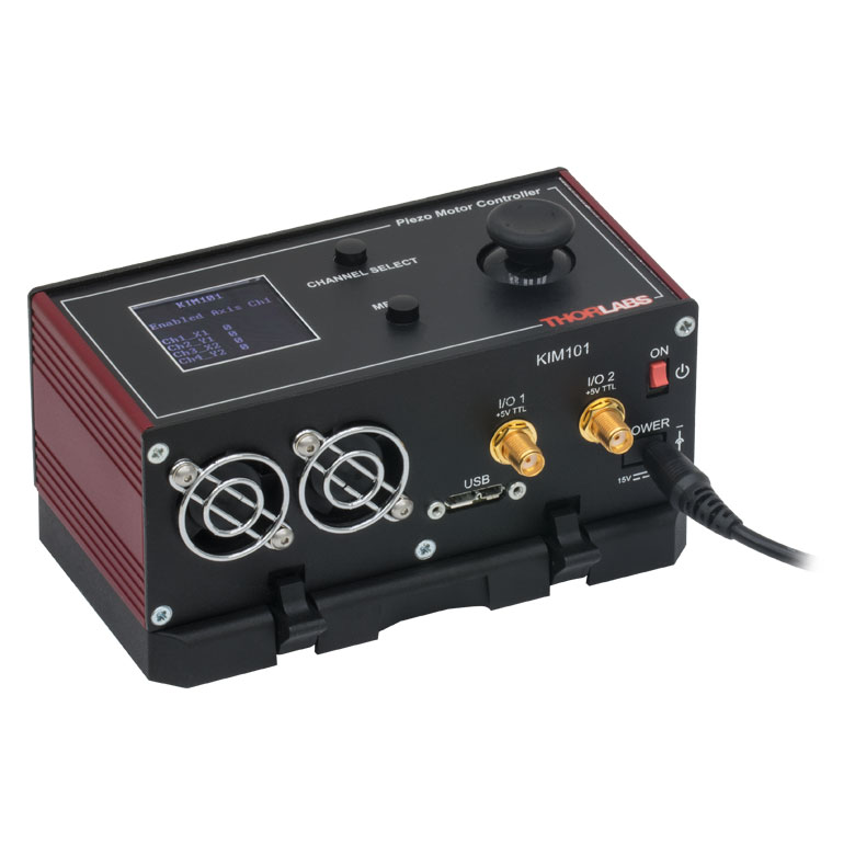
Required Controller
A KIM001 or KIM101 controller is required to operate our PIA13 Piezo Inertia Actuator; the actuator cannot be operated using a standard piezo controller. These drivers have an internal sawtooth voltage signal generator capable of sending sub-millisecond pulses (steps) with controllable amplitudes from 85 V to 125 V. The KIM001 and KIM101 controllers offer one and four output channels, respectively.
For more information, please see the full web presentation here.
Required Controller:
KIM001 or KIM101
- KIM001: Single-Channel Output
- KIM101: Four Output Channels, Capable of Multi-Channel Operation
- Standalone Control via Top Panel or PC Control via USB
- Voltage Output from 85 V to 125 V
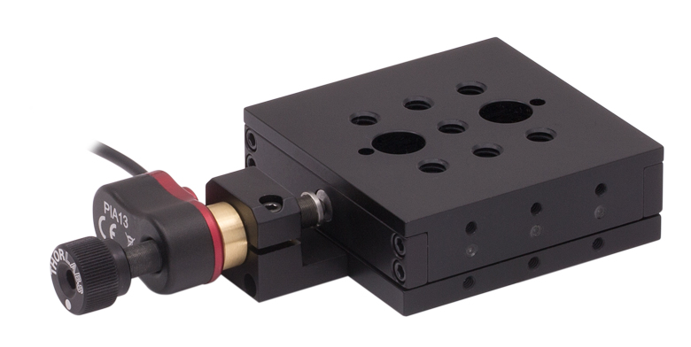
Click to Enlarge
Figure G5.1 PIA13 Inertia Actuator Being Used to Drive an MT1 13 mm Translation Stage
(Stage Sold Separately)

 Zoom
Zoom| Item #a | PIA13VF |
|---|---|
| Travel | 13 mm (0.51") |
| Step Sizeb,c | 10 - 30 nm (Typ.) ≤30 nm (Max) |
| Step Size Adjustabilityd | Up to 30% |
| Max Step Frequency | 2 kHz |
| Backlash | None |
| Max Active Preloade | 25 N |
| Recommended Max Axial Load Capacityf |
2.5 kg (5.5 lbs) |
| Speed (Continuous Stepping)b,c |
1.2 - 3.6 mm/min. (Typ.) ≤3.6 mm/min. (Max) |
| Drive Screw | 1/4"-80 Thread, Hard PVD Coated |
| Motor Type | Piezoelectric Inertia |
| Mounting Featureg (Auxiliary) |
Ø3/8" (Ø9.525 mm) Barrel (3/8"-40 Thread with Lock Nut) |
| Vacuum Rating | 10-6 Torr |
| Operating Temperature | 5 to 40 °C |
| Max Bakeout Temperature | 130 °C |
| Dimensions | 2.34" x 1.24" x 0.67" (59.5 mm x 31.5 mm x 17.0 mm) |
| Mass (Including Cable) | 55 g (1.94 oz) |
| Cable Length | 0.75 m (2.46 ft) Flying Lead for Vacuum, 1.0 m (3.3 ft) Cored Cable for Wiring Outside Chamber |
| Connector | SMC Female |
| Required Controllerh | KIM001 or KIM101 |
- Compact Design: 31.5 mm x 17.0 mm (W x H)
- Manual Adjustment via Knob on Adjuster Screw
- Rated Down to 10-6 Torr
- 125 V Maximum Operating Voltage
- Ø3/8" (Ø9.525 mm) Mounting Barrel for Compatibility with Translation Stages
- Ideal for Set-and-Hold Applications that Require High-Resolution Relative Positioning
- Also Available in 25 mm and 50 mm Travel Versions
Thorlabs' PIA13VF Vacuum-Compatible Piezoelectric Inertia Actuator is rated down to
This actuator has a Ø3/8" (Ø9.525 mm) barrel that can be mounted in a manual stage that has a Ø3/8" (Ø9.525 mm) mounting clamp. For compatibility with 1/4"-100 threaded mirror mounts see our 10 mm travel piezo inertia actuators. The actuator is self-locking when at rest and when there is no power supplied to the piezo, making the actuator ideal for set-and-hold applications that require nanometer resolution and long-term alignment stability. Manual adjustments can be made using the knob on the adjuster screw, as long as the piezo is not actively translating the screw; the knob is also compatible with 5/64" (2.0 mm) hex keys.
Each actuator has an integrated 0.75 m flying lead, plus 1.0 m of cored cable for wiring outside the vacuum chamber. The flying leads and cored cable lengths can be cut down as needed, but the total length (inside and outside) should not exceed 2.0 m. As shown in Figure G6.1, the flying lead for each actuator can be rotated up to 110° for space-constrained applications.
Powered by a 10 mm long discrete piezo stack, the actuator can operate at speeds of up to 3.6 mm/minute. The design of the piezo motor will rotate the tip of the lead screw during translation. For information on the design of this piezo inertia "slip-stick" motor actuator, please see the complete presentation here.
Required Controller
A KIM001 or KIM101 controller is required to operate our PIA13VF Piezo Inertia Actuator; the actuator cannot be operated using a standard piezo controller. These drivers have an internal sawtooth voltage signal generator capable of sending sub-millisecond pulses (steps) with controllable amplitudes from 85 V to 125 V. The KIM001 and KIM101 controllers offer one and four output channels, respectively.
For more information, please see the full web presentation here.
Required Controller:
KIM001 or KIM101
- KIM001: Single-Channel Output
- KIM101: Four Output Channels, Capable of Multi-Channel Operation
- Standalone Control via Top Panel or PC Control via USB
- Voltage Output from 85 V to 125 V
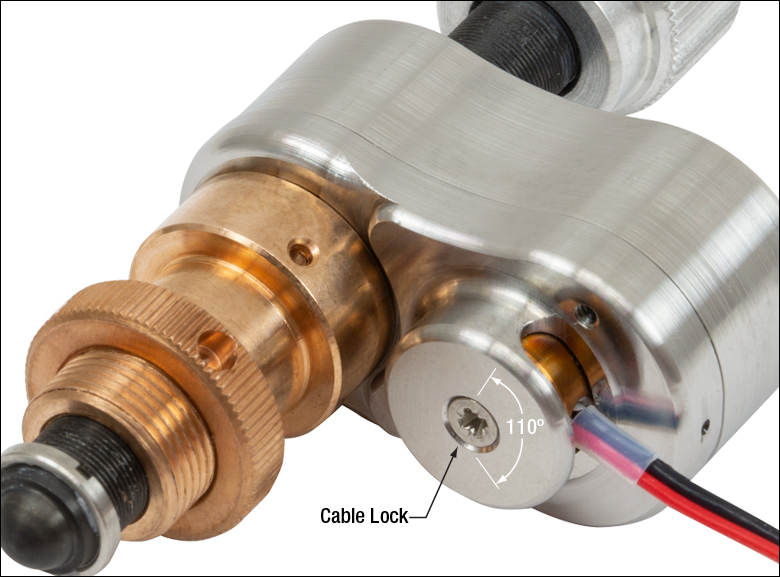
Click for Details
Figure G6.1 The flying lead can be adjusted up to 110° for space-constrained applications.

 Zoom
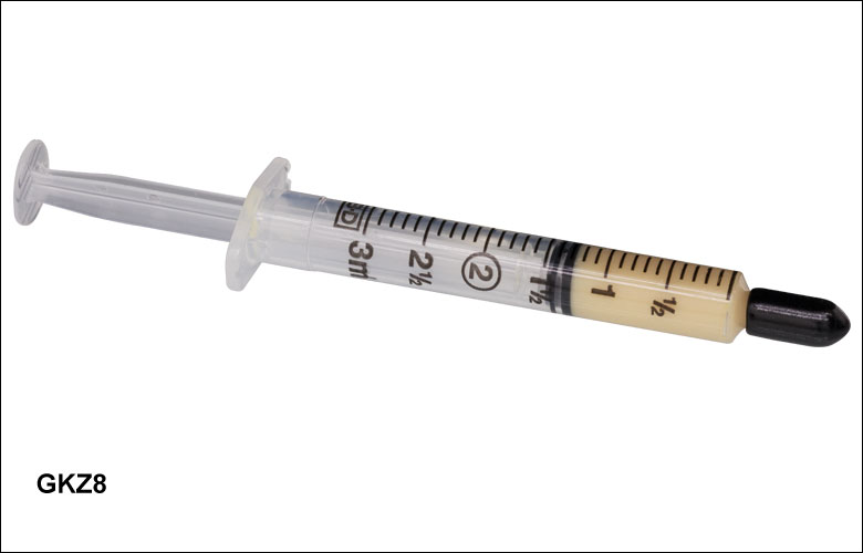
Zoom- 1.5 cc Syringe of Apiezon 100 Grease
- Convenient, Inexpensive Package that Reduces Waste
- Prolongs Lifetime of Actuator
- Ready to Dispense
- Vacuum Compatible to 10-9 Torr
This Apiezon grease has excellent anti-seize properties. It contains PTFE for maximum lubricity and is ideal for re-lubricating the lead screw threads of our ZST, ZFS, and Z9 series actuators. It is supplied in a syringe for easy application and is recommended both for general use and for vacuum applications down to
Note: It is recommended that the lead screw and end ball of the Z9, ZFS, and ZST actuators are lubricated every 10 000 cycles or whenever a squeaking noise is heard during motion.
Thorlabs' DRV, ZST, and ZFS Stepper Motor Actuators, as well as our Z9 DC Servo Motor Actuators, come with cables for connecting to the required controllers. Thorlabs also offers separate cables that may be used as extension cables.
Stepper Motor Cables
Thorlabs offers a variety of cables to support several stepper motor actuator and controller combinations. Supported stepper motors include our ZST, ZFS, and DRV actuators; supported controllers include our BSC benchtop controllers, our KST201 K-Cube® Controller, and our MST602 Rack Control Module. In order to see which cable is compatible with a given combination of stepper motor and controller, please see Table 747A. The pin assignment for each cable is given in the full web presentation here. Please note that these cables cannot be used with motors and controllers that do not match their pin assignment, even if the connectors are the same.
DC Motor Cables
The PAA632 is a 2.5 m cable for our Z9 series of DC motor actuators. This cable is intended to be used with the KDC101 K-Cube DC Servo Motor Controller. The pin assignment for this cable is given in the full web presentation here. Although it uses a 15-pin connector, this cable is not compatible with any of our stepper motors.
| Table 747A Motor and Controller Cable Compatibility | ||
|---|---|---|
| Motor | Controller | Compatible Cable |
  |
 |
PAA614 (1 m) |
| ZST and ZFS Stepper Motor Actuator | KST201 K-Cube Controller | |
 |
|
PAA614 (1 m)a |
| KST201 K-Cube Controller | ||
  |
PAA612 (1 m) or PAA613 (3 m) |
|
| DRV Series Stepper Motor Actuatora | BSC Benchtop Controller and MST602 Rack Controller |
|
 |
 |
PAA632 (2.5 m) |
| Z9 DC Servo Motor Actuator | KDC101 K-Cube Controllerb | |