 Products Home
Liquid Light Guides
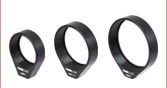
- Wavelength Ranges from 220 to 2000 nm
- Ø3 and Ø5 mm Core Sizes Available from Stock
- 4', 6', or 8' Lengths Available
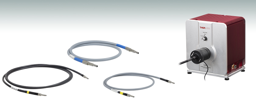
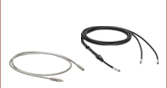
LLG5-4T
220 - 650 nm
Ø5 mm Core, 4' Long
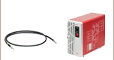
LLG3-8H
340 - 800 nm
Ø3 mm Core, 8' Long
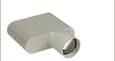
Application Idea
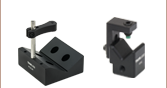
Liquid Light Guides Mounted to
SM2-Threaded Light Source Using
SLSLLG2 Collimating Adapter With Shutter
LLG3-4Z
420 - 2000 nm
Ø3 mm Core, 4' Long


Please Wait
| Quick Links |
|---|
| Liquid Light Guides |
| Ø3 mm Core Liquid Light Guides |
| Ø5 mm Core Liquid Light Guides |
| Liquid Light Guide Adapters |
| SM1 (1.035"-40) Adapters |
| SM2 (2.035"-40) Coupling/Collimating Adapters |
| Multi-Optic Cerna® Microscope Collimating Adapters |
| Single-Optic Microscope Collimating Adapters |
Features
- High Transmission from 220 - 650 nm, 340 - 800 nm, or 420 - 2000 nm
- Suitable for Rugged Environments
- Adapters Designed to Mate Ø3 mm or Ø5 mm Liquid Light Guides to SM1 or SM2 Thread Standard Available Below
- Microscope Collimation Adapters Available Below
Thorlabs' Liquid Light Guides (LLGs) offer high transmission from 220 - 650 nm, 340 - 800 nm, or 420 - 2000 nm (see the Graphs tab for typical performance). These LLGs can be used with our SLS201L(/M) compact quartz tungsten-halogen (QTH) light source, SLS301 and SLS302 benchtop QTH light sources, SLS401 and SLS402 benchtop xenon arc light sources, or SLS204 deuterium UV light source. For large core diameters, liquid light guides are a more efficient transmission solution than fiber bundles as they eliminate the packing fraction loss (dead space) that fiber bundles have.
These liquid light guides are offered from stock with a core diameter of either 3 or 5 mm, and in lengths of 4' (1.2 m), 6' (1.8 m), or 8' (2.4 m). LLG3-4T and LLG5-4T light guides can have either end used as an input. LLG3-4Z and LLG5-4Z liquid light guides have a yellow band that indicates the end that must be used as the input because it contains a filter to protect the light guide from radiation below 420 nm. Light guides with a 340 - 800 nm wavelength range each have a yellow band that acts as a visual indicator for use with our previous-generation HPLS343 (for Ø3 mm core) or HPLS345 (for Ø5 mm core) high-power plasma light sources; the LLG is correctly inserted when the edge of the band is flush with the front panel of the instrument.
These light guides can be mounted to an optical breadboard by using one of our VH1(/M) V-Mounts, a Ø1/2" (12.7 mm) post, and post holder. They can also be mounted to SM1-threaded (1.035"-40) components, SM2-threaded (2.035"-40) components, or microscope ports using the adapters sold below. Thorlabs also offers collimating and coupling adapters for the liquid light guides, which are sold separately below. The SLSLLGx coupling/collimating adapters feature external SM2 (2.035"-40) threading on the housing that makes them directly compatible with our benchtop light sources. Additionally, we offer a variety of collimating adapters that allow the LLGs to be coupled to a Cerna® microscope or the illumination ports used by various microscope manufacturers.
All of our LLGs are available with custom core diameters or custom lengths as made-to-order items by contacting Tech Support.
All transmission data presented here is typical. The data was taken with a bend radius of 400 mm and the maximum variation from lot to lot is 5%. As a function of length, only minimal variations (<5%) are expected between our 4' (1.2 m), 6' (1.8 m), and 8' (2.4 m) long liquid light guides. The blue-shaded region in each graph denotes the spectral range over which we recommend using that liquid light guide.
Ø3 mm Core Liquid Light Guides
 Click to Enlarge
Typical Transmission of LLG3-4T. The transmission was measured using an input light source with a full entrance angle of 34°.
 Click to Enlarge
Typical Transmission of LLG03-4H. The transmission was measured using an input light source with a full entrance angle of 50°.
Click to Enlarge
Typical Transmission of LLG3-6H. The transmission was measured using an input light source with a full entrance angle of 50°.

Click to Enlarge
Typical Transmission of LLG3-8H. The transmission was measured using an input light source with a full entrance angle of 50°.
Click to Enlarge
Typical Transmission of LLG3-4Z. The transmission was measured using an input light source with a full entrance angle of 50°.
Ø5 mm Core Liquid Light Guides
Click to Enlarge
Typical Transmission of LLG5-4T. The transmission was measured using an input light source with a full entrance angle of 34°.
Click to Enlarge
Typical Transmission of LLG05-4H. The transmission was measured using an input light source with a full entrance angle of 50°.

Click to Enlarge
Typical Transmission of LLG5-6H. The transmission was measured using an input light source with a full entrance angle of 50°.
Click to Enlarge
Typical Transmission of LLG5-8H. The transmission was measured using an input light source with a full entrance angle of 50°.
Click to Enlarge
Typical Transmission of LLG5-4Z. The transmission was measured using an input light source with a full entrance angle of 34°.
Liquid Light Guide Dimensions
| Table 3.1 Liquid Light Guide Dimensions | |||||||||
|---|---|---|---|---|---|---|---|---|---|
| Item # | Active Core Diameter | Standard End Fittings | Protective Sleeve | Min Bend Radius | |||||
| d0 | d1 | l1 | d2 | l2 | d3 | I3 | d4 | ||
| LLG3-4T | Ø3 mm | Ø5 +0/-0.1 mm | 20 ± 0.1 mm | Ø9 ± 0.1 mm | 30 ± 0.1 mm | N/A | N/A | Ø7.5 mm | 50 mm |
| LLG03-4H, LLG3-6H, LLG3-8H LLG3-4Z | Ø3 mm | Ø5 +0/-0.1 mm | 20 ± 0.1 mm | Ø9 ± 0.1 mm | 24 ± 0.1 mm | N/A | N/A | Ø7 mm | 40 mm |
| LLG5-4T | Ø5 mm | Ø7 +0/-0.1 mm | 20 ± 0.1 mm | Ø10 ± 0.1 mm | 24 ± 0.1 mm | Ø13 ± 0.1 mm | 24 ± 0.1 mm | Ø10.5 mm | 70 mm |
| LLG05-4H, LLG5-6H, LLG5-8H LLG5-4Z | Ø5 mm | Ø7 +0/-0.1 mm | 20 ± 0.1 mm | Ø10 ± 0.1 mm | 24 ± 0.1 mm | N/A | N/A | Ø9.5 mm | 60 mm |
Figures 3.2, 3.3, and 3.4 illustrate the dimensions given in Table 3.1.
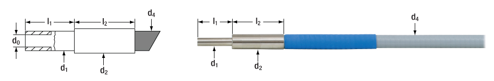 Figure 3.2 Dimensions for the LLG3-4T Liquid Light Guide are shown in Table 3.1.
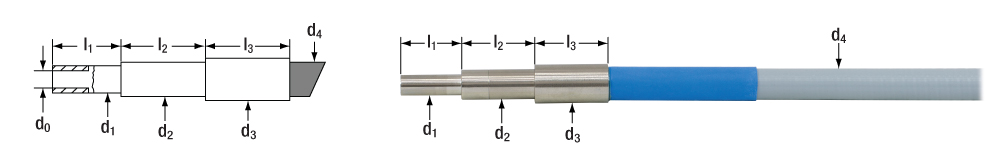 Figure 3.3 Dimensions for the LLG5-4T Liquid Light Guide are shown in Table 3.1.
 Figure 3.4 Dimensions for the LLG0x-4H, LLGx-xH, and LLGx-4Z Liquid Light Guides are shown in Table 3.1.
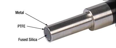
Cleaning the Optical End Faces of Liquid Light Guides
The optical end faces of these liquid light guides are made of fused silica, PTFE and either aluminum, chrome plated brass, or stainless steel. All of these materials are very resistant to all common cleaning solvents, making them easy to clean. Please note that when using solvents to clean the end faces, you cannot submerge the tip of the light guide in the solvent, or use a heavily soaked cleaning pad, as the solvent may get into the light guide, causing damage. If you find that debris from the light guide end cannot be removed by using a solvent, you can gently use a razor blade to clean the tip, making sure that you do not chip the edge of the fused silica glass window.
| Posted Comments: | |
Elizabeth Bullard
(posted 2023-10-19 13:57:02.71) Hello,
Could I get the raw data for the transmission spectrum on the LLG5-4Z?
Thank you! cdolbashian
(posted 2023-10-27 03:43:03.0) Thanks for contacting Thorlabs! The transmission of the LLG5-4Z is heavily related to the input beam size and NA so we provide the graph for relative reference. Please see the links on the "Overview" and "Graphs" tab for more information. Tomas Iser
(posted 2023-08-25 21:32:35.28) Hello, how well does the SLSLLG3 adapter collimate the light beam coming from a 5 mm light guide? What is the difference between SLSLLG3 and the more expensive microscope collimators (e.g., LLG5A1-A or LLG5A6)? Thank you! cdolbashian
(posted 2023-08-30 11:49:55.0) Thank you for contacting Thorlabs. The SLSLLG3 adapter is designed to couple the light from the light source to the light guide, while microscope collimators (e.g., LLG5A1-A or LLG5A6) are designed to collimate the light beam from the light guide. So we recommend only using microscope collimators to collimate the light. With regards to the collimation quality, we suggest looking into the concepts of etendue and the optical invariant. There is inherently a limit to how well something can be collimated based on the source's parameters. I have contacted you directly to discuss these concepts. Derek Decker
(posted 2023-07-06 14:13:38.037) Can we get a Zemax OpticStudio blackbox model of a liquid light guide? The one I have and measured goes like Cosine to the 14th power with a hard edge at the NA. cdolbashian
(posted 2023-07-14 04:33:07.0) Thank you for contacting Thorlabs! We currently don't have the Zemax OpticStudio blackbox models of liquid light guides. Our liquid light guides have a core diameter from Φ3 mm to Φ5 mm, therefore they support more than millions of transmission modes. Generally the higher the number of the transmission modes, the sharper the edge of the output beam profile. seongjun park
(posted 2023-06-27 13:24:38.493) Hello,
Can get a Zemax blackbox model of this item (LLG3A6)?
Thank you.
Best,
Sengjun. jpolaris
(posted 2023-07-31 07:00:50.0) Thank you for contacting Thorlabs. Zemax blackbox models for our parts can be requested by contacting us as techsupport@thorlabs.com. I have reached out to you directly to assist in arranging this. Clement Jonglez
(posted 2023-03-23 15:19:14.603) Hello,
We are considering using the SLSLLG1 and LLG5-4Z on a ScienceTech SF-300-A Sun simulator, would these liquid light guide products survive the beam power?
The SF-300-A outputs a collimated beam (25mm diameter, 1° divergence) with a power of 1 Sun. cdolbashian
(posted 2023-04-04 11:04:19.0) Thank you for contacting Thorlabs. For this CW light source, the damage is dependent on how well the LLG is cooled. We recommend keeping an eye on the temperature of the liquid light guide. The long‐term temperature range for the LLG5-4Z is from +5 to 35 °C. maelle.ogier
(posted 2017-10-13 17:08:15.837) Hello, we are looking for an adapter to make a coupling between an Intensilight Nikon source, which outputs through their 3mm core light guide and a fiber with SMA905 connector. Is there a simple way to do this ? We are wondering if we need to invest in micropositioning alignment ? and beam focusing ? What are the different options ? (given that the source probably delivers much more power than needed now). Thanks in advance. Maelle tfrisch
(posted 2017-10-20 02:12:55.0) Hello, thank you for contacting Thorlabs. The coupling efficiency from a LLG to a fiber will typically be poor as the LLG will have a larger core and NA in most cases. Using a lens to focus the light will cause greater losses due to increasing the effective NA of the light, so butt-coupling is often close to the upper bound of coupling efficiency. I will reach out to you directly to discuss your LLG and how to best couple it to an SMA fiber. harris.morrison
(posted 2017-08-09 13:13:21.947) Hi,
Am about to dispose of a light guide and was wondering if there were any hazards associated with the light guide? Science being what it is now, they like to make sure we use the correct dumping procedure.
Many thanks,
Harris tfrisch
(posted 2017-09-06 12:01:28.0) Hello Harris, thank you for contacting Thorlabs. I will reach out to you directly about returning that LLG to us for disposal. carlos.macias
(posted 2017-06-28 17:54:23.457) Hello. Is it possible to couple the light from MNWHL4 into one of your light guides? tfrisch
(posted 2017-07-11 10:22:39.0) Hello, it looks like you have already been in contact with our Tech Support team, but yes, AD3LLG and AD5LLG would be useful in adapting the LLG to a lens tube system which may contain optics to collect the light, or may just hold the LLG near the emitting LED. jjgarcia
(posted 2017-01-31 04:23:40.78) Would you have a liquid light guide (LLG) like the one with the reference number: LLG0338-4, but for VIS-NIR wavelength range (say with transmission around 80% up to 1000nm or 1500nm)
Thanks! tfrisch
(posted 2017-02-16 02:26:16.0) Hello, thank you for contacting Thorlabs. Unfortunately, we cannot offer a custom version of the liquid light guide optimized for NIR at this time. I will reach out to you directly. bobkov
(posted 2014-09-17 15:21:35.837) Could you please provide me with the transmission spectrum of LS liquid light guide (within range 200-1000nm)? I would love to have it in some sort of ASCII data or other data formats rather than a graphic material. Many thanks in advance. jlow
(posted 2014-09-19 01:04:32.0) Response from Jeremy at Thorlabs: We can provide the raw data for the graphs online. I will contact you directly about this and we will look into having that available to download from the website as well. jcarreras77
(posted 2014-05-29 10:34:23.263) Hi there. We are fabricating a prototype for a commercial product and we would like to couple the light output of an LED spotlight into a LLG (visible range, total optical power of 7W). The spotlight is made of a 40 LED PCB of 4x4cm with a conic reflector that makes a 25º aperture beam with a 7.5 diameter glass at the end of the system. Can you please tell me what kind of aspherical lenses and coupling systems from Thorlabs should we use? Thank you! besembeson
(posted 2014-05-29 04:31:33.0) A response from Bweh E at Thorlabs Newton-USA: Thanks for contacting Thorlabs. I will followup with you by email to clarify your source characteristics so that we can determine best optical components for coupling to the LLG. bdada
(posted 2012-03-15 13:00:00.0) Response from Buki at Thorlabs:
We would not recommend a laser source for use with the Liquid Light Guides. The only light sources for the LLG that we have tested are our HPLS243 and HPLS245 plasma light sources. In addition to our light sources, we also recommend tungsten halogen, xenon or metal halide light sources.
Please contact TechSupport@thorlabs.com to discuss your application further so we can suggest alternative solutions. user
(posted 2012-03-07 11:59:32.0) Are LLGs suitable for delivery of 532nm pulsed laser sources? Jon bdada
(posted 2012-01-25 16:42:00.0) Response from Buki at Thorlabs:
Thank you for using our feedback forum. The only light sources for the LLG that we have tested are our HPLS243 and HPLS245 plasma light sources.
In addition to our light sources, we also recommend tungsten halogen, xenon or metal halide light sources. For any light source, the main factors to consider are the wavelength range and possible overheating.
Light below 400nm and above 750 - 800nm could damage the LLG and should be filtered out. If the temperature of the LLG stays above 35 degrees Celcius for a prolonged period, it could affect the transmisison properties.
We have contacted you to provide additional information. iftachn
(posted 2012-01-18 09:45:26.0) Would this light guide work well for a mercury lamp illuminator such as the Nikon Intensilight ? bdada
(posted 2012-01-12 20:02:00.0) Response from Buki at Thorlabs:
The liquid light guide is recommeded for use with tungsten halogen, xenon or metal halide light sources.
If you are looking for a fiber coupled LED (MCWHL2), please consider MCWHF1 - Cold White (5600K) Fiber-Coupled High-Power LED, SMA, 1000 mA. The product link is below. You would need to purchase the fiber cable separately. Please contact TechSupport@thorlabs.com if you have any questions.
http://thorlabs.com/NewGroupPage9.cfm?ObjectGroup_ID=5206 user
(posted 2012-01-12 14:21:25.0) Is it possible to use the liguid light guide with an LED (part # MCWHL2)? Tefo jjurado
(posted 2011-07-25 10:02:00.0) Response from Javier at Thorlabs to ckonek: Thank you very much for contacting us. We currently do not sell collimators specifically designed for liquid light guides. However, we do offer a few components that you can use to put together your own collimation insert. For example, if you are interested in the 5 mm core diameter liquid light guides, you can use an AD8F adapter to mount the LLG into an SM1 lens tube like the SM1M20. In order to collect the output from the LLG, you can use a condenser lens like ACL2520. Keep in mind that the output from the lens will still be divergent, due to the large core size of the LLG.
AD8F: http://www.thorlabs.com/NewGroupPage9.cfm?ObjectGroup_ID=1746
SM1M20: http://www.thorlabs.com/NewGroupPage9.cfm?ObjectGroup_ID=3307&pn=SM1M20#3387
ACL2520: http://www.thorlabs.com/NewGroupPage9.cfm?ObjectGroup_ID=3835 ckonek
(posted 2011-07-20 10:33:59.0) Im wondering if you sell collimators for your liquid light guide products.
Chris Thorlabs
(posted 2010-09-22 11:45:51.0) Response from Javier at Thorlabs to walter.clark: the main advantage of liquid light guides over fiber bundles is their large numerical aperture. Our liquid light guides have a numerical aperture of 72°, whereas most common fiber bundles have an NA around half of this value. Another advantage is that liquid light guides eliminate the packing fraction loss (dead space) that fiber bundles have. walter.clark
(posted 2010-09-20 17:42:50.0) I dont understand why liquid is better than solid.
Is it because it is more flexible? Then why not bundle more fibers?
Walt |
| Item # | LLG3-4T | LLG03-4H | LLG3-6H | LLG3-8H | LLG3-4Z |
|---|---|---|---|---|---|
| Wavelength Range | 220 - 650 nm | 340 - 800 nm | 420 - 2000 nm | ||
| Numerical Aperture | 0.42 | 0.59 | 0.52 | ||
| Half Angle (θ) | 25° | 36° | 31° | ||
| Minimum Bend Radius | 50 mm | 40 mm | 40 mm | ||
| Operating Temperature Range | 5 to 30 °C (41 to 86 °F) | -5 to 35 °C (23 to 95 °F) | 5 to 35 °C (41 to 95 °F) | ||
| Transmission (Click for Plot) | |||||
| Available Lengths | 4' (1.2 m) | 4' (1.2 m) | 6' (1.8 m) | 8' (2.4 m) | 4' (1.2 m) |
| Input End Indicator | N/A | Yellow Banda | Yellow Bandb | ||
| Item # | LLG5-4T | LLG05-4H | LLG5-6H | LLG5-8H | LLG5-4Z |
|---|---|---|---|---|---|
| Wavelength Range | 220 - 650 nm | 340 - 800 nm | 420 - 2000 nm | ||
| Numerical Aperture | 0.42 | 0.59 | 0.52 | ||
| Half Angle (θ) | 25° | 36° | 31° | ||
| Minimum Bend Radius | 70 mm | 60 mm | 60 mm | ||
| Operating Temperature Range | 5 to 30 °C (41 to 86 °F) | -5 to 35 °C (23 to 95 °F) | 5 to 35 °C (41 to 95 °F) | ||
| Transmission (Click for Plot) | |||||
| Available Lengths | 4' (1.2 m) | 4' (1.2 m) | 6' (1.8 m) | 8' (2.4 m) | 4' (1.2 m) |
| Input End Indicator | N/A | Yellow Banda | Yellow Bandb | ||

 Zoom
Zoom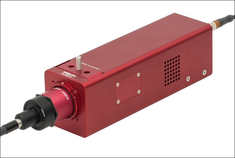
Click to Enlarge
Figure G3.1 An SM1 Adapter for Liquid Light Guides is used with a lens tube to couple the output of a light source into a liquid light guide. Adjusting the depth of the SM1 adapter in the lens tube is necessary in order to achieve maximum throughput.
- Designed to Mate Ø3 mm or Ø5 mm Liquid Light Guides to SM1 Standard
- External SM1 (1.035"-40) Threading
These Liquid Light Guide Adapters allow the integration of our Ø3 mm and Ø5 mm liquid light guides into any of our selection of SM1-threaded (1.035"-40) components, such as fixed optic mounts, kinematic optic mounts, and lens tubes. The LLG is secured with a nylon-tipped setscrew using a 1/16" hex key (found in the CCHK kit).

 Zoom
Zoom
Click to Enlarge
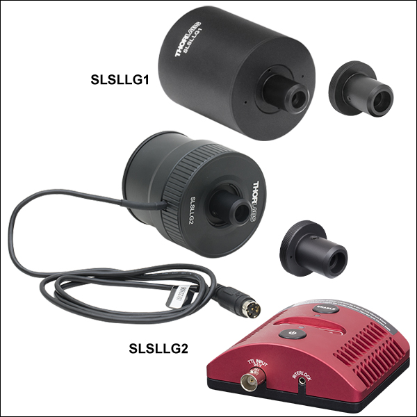
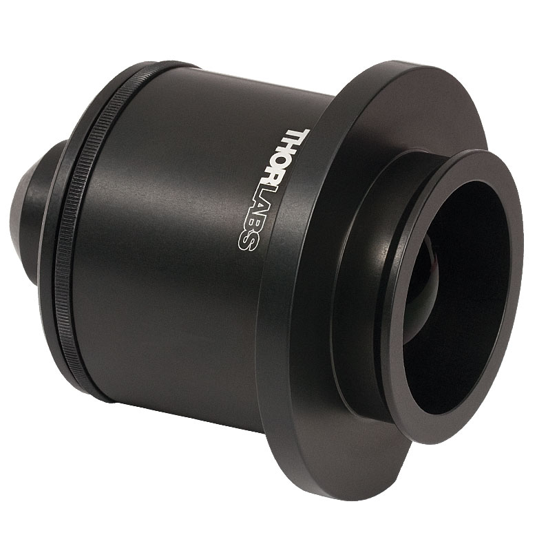
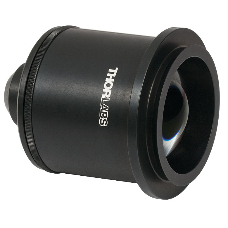
Figure G4.1 An SLSLLG2 LLG adapter, with a liquid light guide, attached to an SLS402 light source.
- Collimate Light from or Couple Light into Ø3 mm and Ø5 mm Core Liquid Light Guide
- Externally SM2-Threaded (2.035"-40) Mounting Threads
- 185 nm - 2.1 µm or 350 - 700 nm Wavelength Range
- SLSLLG2 Includes Integrated Electronic Shutter with External Controller
- Directly Compatible with SLS301, SLS401, and SLS402 Broadband Light Sources
These Liquid Light Guide Adapters allow the integration of our Ø3 mm and Ø5 mm liquid light guides into any of our selection of SM2-threaded (2.035"-40) components, in particular our SLS301, SLS401, and SLS402 broadband light sources. The adapter can be directly threading onto a light source without the need to adjust the position of the collimating lens.
The SLSLLG1 is designed with an uncoated collimating lens, which provides a wide operating range from 185 nm - 2.1 µm. For superior performance from 350 nm - 700 nm, the SLSLLG2 and SLSLLG3 lenses use an AR-coated lens that provides improved coupling efficiency in this wavelength range. Additionally, the SLSLLG2 features an integrated diaphragm shutter and an external controller that can operate at continuous frequencies up to 10 Hz and burst frequencies up to 15 Hz. For more information on the integrated shutter, please refer to the manual.
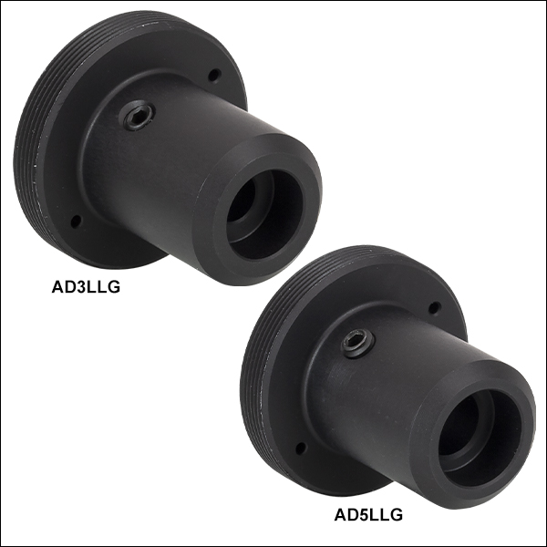
All liquid light guide adapters come with a Ø3 mm LLG to SM1 (Ø1.035"-40) AD3LLG adapter preinstalled, making them compatible with Ø3 mm core liquid light guides out of the box. They are also shipped with a Ø5 mm LLG to SM1 (Ø1.035"-40) AD5LLG adapter, which can be swapped in by unthreading the AD3LLG and replacing it with the AD5LLG. This allows the adapters to connect with Ø5 mm core liquid light guides.
| Item # | SLSLLG1 | SLSLLG2 | SLSLLG3 | ||||
|---|---|---|---|---|---|---|---|
| Wavelength Range | Uncoated: 185 nm - 2.1 µm | AR Coated: 350 nm - 700 nm; Ravg < 0.5% | |||||
| Integrated Electronic Shutter | No | Yesa | No | ||||
| Lens | LA4464 | ACL5040U-A | |||||
| Lens Material | UV Fused Silica | B270 Optical Crown Glass | |||||
| Coupling Efficiency | SLS401 / SLS402 | >30% (3 mm LLG); >35% (5 mm LLG) | >30% (3 mm LLG); >40% (5 mm LLG) | ||||
| SLS301 | >15% (3 mm LLG); >25% (5 mm LLG) | >20% (3 mm LLG); >30% (5 mm LLG) | |||||
| Housing Threading | External SM2 (2.035"-40) | ||||||

 Zoom
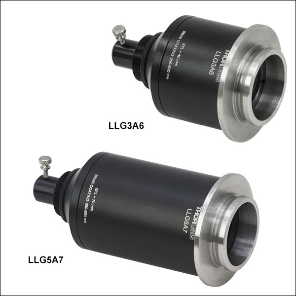
ZoomThorlabs offers collimation adapters to couple Ø3 mm or Ø5 mm liquid light guides (LLGs) to our CSE2100 and CSE2200 Cerna Epi-Illuminator Modules; see Table 644C for compatibility information. For even illumination at the back focal plane of the objective, these adapters feature an optic pair of an achromatic doublet and a double convex lens.
These adapters utilize a male D3T dovetail adapter to connect to the end of the epi-illuminator module; for additional information about microscope dovetails, see the full web presentation. The LLG is secured via a thumbscrew at the back of the adapter.
These adapters are calibrated such that the image plane from the LLG output is located at the back aperture of the objective when used with the compatible epi-illuminator module; to optimize illumination for your microscope or realign the image plane, the collimation can be fine-adjusted via the knurled ring on the thread adapter (see Figure 644A).
| Table 644C Specifications | ||||
|---|---|---|---|---|
| Item # | LLG3A6 | LLG5A6 | LLG3A7 | LLG5A7 |
| Effective Focal Length | 40 mm | 70 mm | ||
| Compatible Epi-Illuminator Module |
CSE2100 | CSE2200 | ||
| LLG Diameter | 3 mm | 5 mm | 3 mm | 5 mm |
| Collimating Optics | Achromatic Doublet & Double Convex Lens |
|||
| AR Coating | 350 nm - 650 nm Ravg < 0.5% at Each Surface |
|||
| Transmission Graph (Click Here for Raw Data) |
 |
|||
| Numerical Aperture | 0.3 |
|||
| Magnification | Infinite | |||
Click to Enlarge
Figure 644A Cutaway View of LLG Collimation Adapter Depicting Multi-Element Design
Click for Details
Figure 644B These simulations illustrate chromatic focal shift in a system with a collimated light source and a CSE2100 epi-illuminator module. A collimation adapter using a single optic (top) produces a larger focal shift for different wavelengths at the objective back aperture compared to a collimation adapter with a multi-element design (bottom).

 Zoom
Zoom
Click to Enlarge
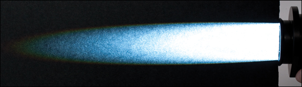
Figure 374C Output With Collimation Adapter
Click to Enlarge
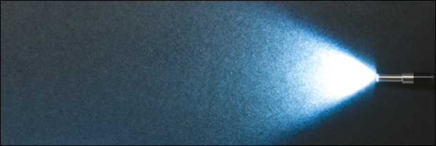
Figure 374B Output Without Collimation Adapter
Click to Enlarge
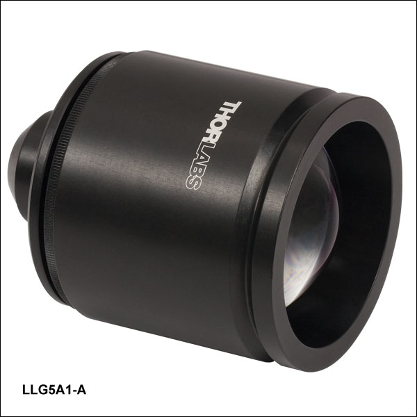
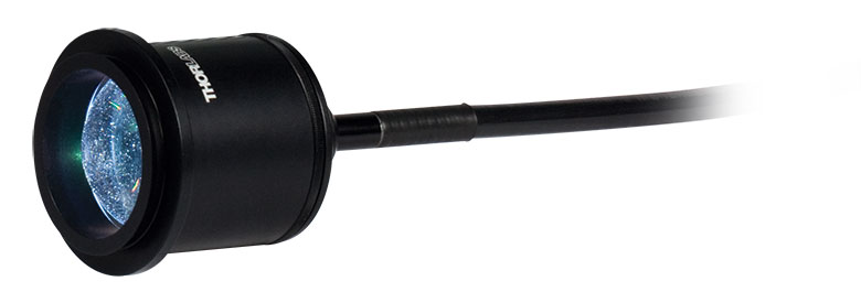
Figure 374A Collimation Adapter Fitted to the Tip of an LLG
Thorlabs offers collimation adapters with AR-coated aspheric condenser lenses (EFL = 40 mm) for collimating the output from our light sources. Four different collimator housings are available; each is designed to mate to the illumination port on an Olympus IX/BX, Leica DMI, Zeiss Axioskop, or Nikon Eclipse Ti microscope.
These adapters quickly mount onto the end of either the Ø3 mm or Ø5 mm Liquid Light Guide (LLG). The LLG is secured into the back of the collimator via a 4-40 setscrew with a 0.050" hex.
| Compatible Microscopes |
Olympus BX & IX Microscopes |
Leica DMI Microscopes |
Zeiss Axioskop Microscopes |
Nikon Eclipse Ti Microscopes |
||||
|---|---|---|---|---|---|---|---|---|
| Item Photo (Click to Enlarge) |
 |
 |
 |
 |
||||
| Item # | LLG3A1-A | LLG5A1-A | LLG3A2-A | LLG5A2-A | LLG3A4-A | LLG5A4-A | LLG3A5-A | LLG5A5-A |
| LLG Diameter | 3 mm | 5 mm | 3 mm | 5 mm | 3 mm | 5 mm | 3 mm | 5 mm |
| Optic Specifications | |
|---|---|
| Item # | ACL5040U-A Aspheric Condenser Lens |
| AR Coating | 350 nm - 700 nm, Ravg <0.5% at Each Surface |
| Focal Length | 40.00 mm ± 8% |
| NA | 0.60 |
| Magnification | Infinite |
| Surface Quality | 80-50 Scratch-Dig |
| Centration | <30 arcmin |