 产品首页
产品首页分辨率测试靶
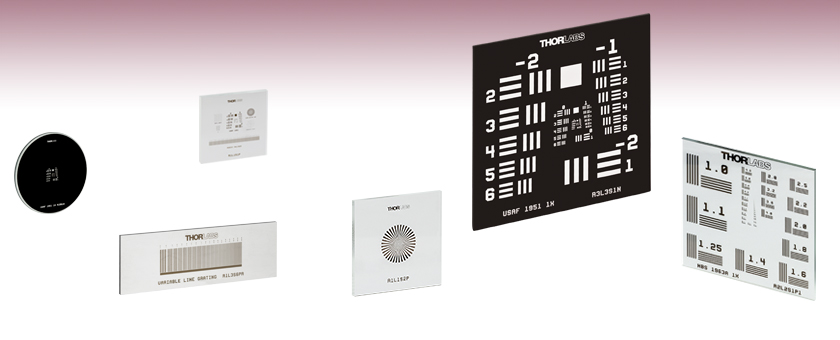
- Test Targets Identify Resolution of an Imaging System
- Positive, Negative, or Birefringent Pattern
- Combined Resolution and Distortion Targets Available
R1DS1N
Ø1" 1951 USAF Target
R1L3S6PR
Reflective Variable Line Grating Target
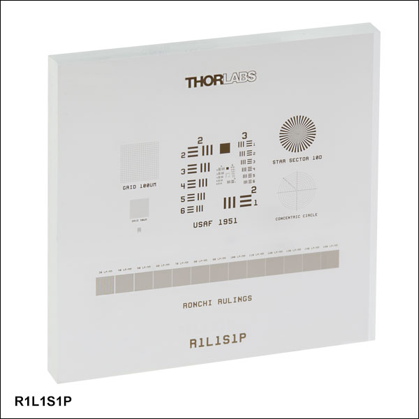
R1L1S1P
Combined Resolution
and Distortion Target
R3L3S1N
Negative 1951 USAF Target
R1L1S2P
Sector Star Target
R2L2S1P1
Positive, High-Frequency
NBS 1963A Target


Please Wait
| Type | Photolithographic | Birefringent |
|---|---|---|
| Design | Chrome-on-Glass | Birefringent Pattern |
| Substrate | Clear Soda Lime Glassa | Variesb |
| Substrate Thickness | 0.06" (1.5 mm) | Variesb |
定制和OEM测试靶
如果您有测试靶的定制或OEM项目,我们很乐意向您介绍我们定制本页所售产品的能力。如需了解更多信息,请访问定制能力标签,或直接联系我们,以讨论您的具体应用。
Click to Enlarge
测试靶定制示例

Jason Williamson
Director of Business Development
Thorlabs Spectral Works
我们期待与您讨论!
特性
- 1951 USAF分辨率测试靶,Ø1英寸
- 1951 USAF分辨率测试靶,1英寸 x 1英寸
- 1951 USAF分辨率测试靶,1.5英寸 x 1.5英寸
- 1951 USAF分辨率测试靶,3英寸 x 1英寸
- 1951 USAF双折射分辨率测试靶,3英寸 x 1英寸
- 1951 USAF分辨率测试靶,3英寸 x 3英寸
- NBS 1952分辨率测试靶,3英寸 x 1英寸
- NBS 1952分辨率测试靶,3英寸 x 3英寸
- NBS 1963A分辨率测试靶,2英寸 x 2英寸
- NBS 1963A分辨率测试靶,高频,2英寸 x 2英寸
- NBS 1963A双折射分辨率测试靶,2英寸 x 2英寸
- 扇形星靶,1英寸 x 1英寸
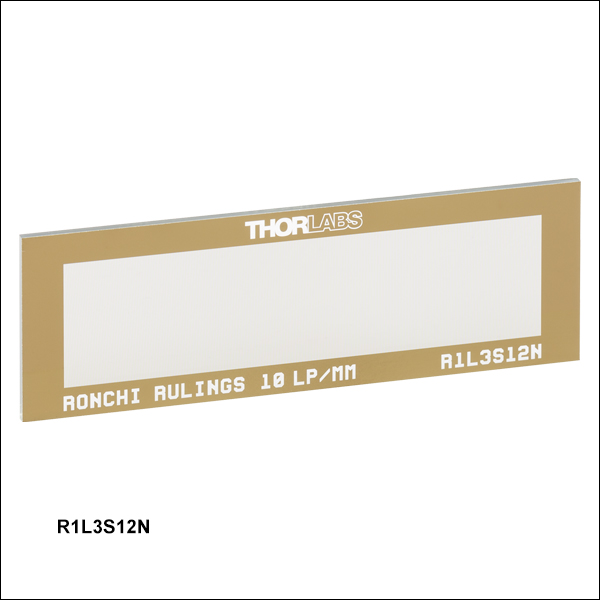
- 朗奇刻线测试靶,3英寸 x 1英寸
- 可变线栅,3英寸 x 1英寸
- 同心圆和十字线网格靶,3英寸 x 3英寸
- 分辨率和畸变组合测试靶,18 mm x 18 mm
- 分辨率和畸变组合测试靶,3英寸 x 1英寸
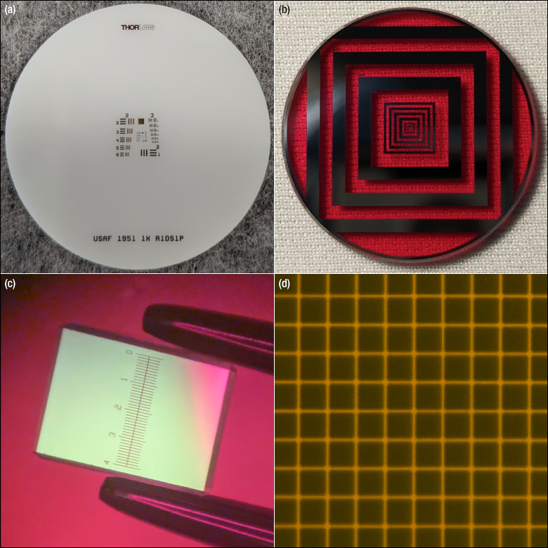
分辨率测试靶通常用来测量成像系统的分辨率。它们包含确定线宽和间距的参考线图样,可放在与成像物体相同的平面。通过识别最大不可分辨线集确定给定系统的分辨能力。Thorlabs提供带1951 USAF、NBS 1952和NBS 1963A图案的分辨率测试靶,以及带扇形星(也叫西门子星)图案的测试靶、朗奇刻线测试靶、可变线栅测试靶或用于测试分辨率和畸变的组合图案测试靶。关于每种图案的更多信息,请见分辨率测试靶标签。
我们所有的分辨率测试靶都提供正测试靶可选,很多类型还有负测试靶版本。我们还提供一些具有高对比度的反射式正测试靶。正测试靶在透明基底上通过真空溅射镀上低反射率铬图案,用于前方照明和一般应用。负测试靶也是在基底上镀低反射率铬膜,留出透明的图案,适用于背光照明和高亮度照明应用。反射式正测试靶具有刻在钠钙玻璃上的低反射率铬图案,带有未镀膜的铬背景,用于反射应用中的高对比度。有关这些测试靶所使用材料的光谱数据,请查看曲线图标签。每种图案都使用光刻制造,边缘特征分辨率可达约1 µm。
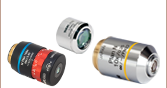
安装
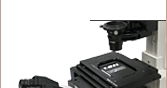
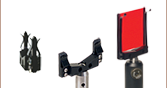
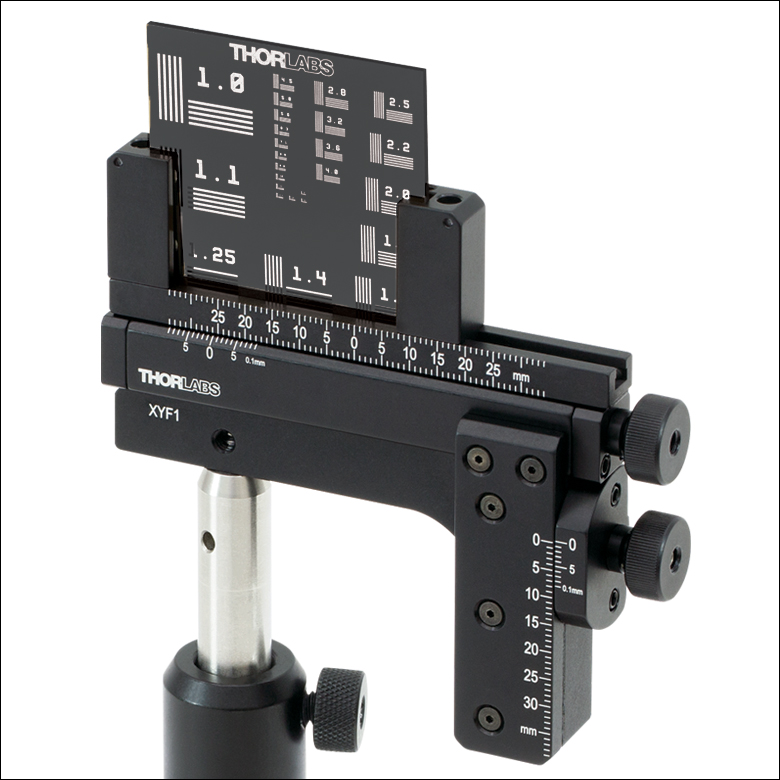
这些分辨率测试靶使用我们四种载玻片支架中的一种安装。我们的MAX3SLH固定式载玻片支架使用两个弹簧片固定光学元件,可以安装在我们任意的3轴位移台上。MAX3SLH仅兼容宽度大于或等于2英寸的测试靶,提供1英寸通光孔径,有可能遮住某些测试靶上的铬图案。Thorlabs也提供XYF1(/M)测试靶安装座(请看右图),可以将宽度为1英寸到3英寸的矩形靶在50 mm x 30 mm的区域内移动。该安装座有五个8-32(M4)螺孔,可在六个方向上安装接杆。XYF1使用尼龙顶丝固定光学元件。请注意,安装座的支撑臂与光学元件两端都有4.4 mm重叠。对于高速电动XY扫描位移台用户,我们提供用于倒置显微镜的MLS203P2载玻片支架,可以安装25 mm至26.5 mm宽的载波片和30 mm到60 mm直径的培养皿。
光刻测试靶生产
我们的大批量生产能力可以给成像系统校正和测量提供解决方案。我们使用接触式光刻技术和掩模对准器在玻璃基底上定义图样。图案定好后,我们在100级洁净室中以化学法刻蚀基底并清洁。
双折射测试靶生产
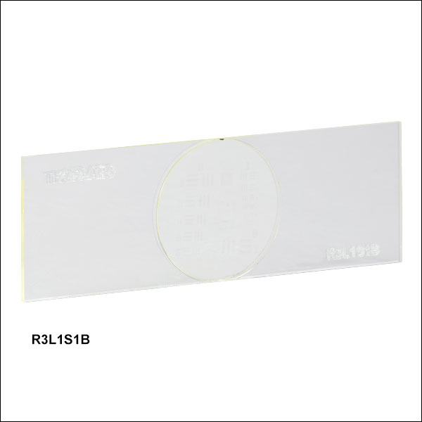
R3L1S1B和R2L2S1B双折射分辨率测试靶上的图案必须通过一对正交偏振片才能看到,非常适合偏振敏感系统的校准。使用光取向技术设定液晶聚合物层的快轴,通过两块N-BK7玻璃保护。通过工程加工使测试靶整体的快轴平行于玻璃边,而图案区域的快轴与这个边缘成45°。整个测试靶的延迟量为280 ± 20 nm。此外,通过改变正交偏振片的方向,测试靶可以呈现正负图案。如果正交偏振片与玻璃边对准,则呈现正图案。如果正交偏振片与玻璃边成45°,则呈现负图案。
Thorlabs还提供一系列分划板,用于在成像物体上叠加一个参考图样。
| Targets Selection Guide | ||||
|---|---|---|---|---|
| Resolution Test Targets | Calibration Targets | Distortion Test Targets | Slant Edge MTF Target | Stage Micrometers |
Click to Enlarge
图2.1 线对帮助确定相机区分两个物体的能力。
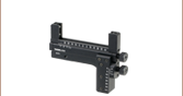
成像分辨率
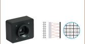
成像系统分辨率通常以每毫米的线对(lp/mm)表示,其中线对为一条亮线和一条暗线。这个数值表示系统所能区分的两个物体之间的最小距离;lp/mm值越高,线对之间的距离越小。
图2.1描绘系统的分辨率极限。通过左边相机成像的线对无法分辨;这两条线通过相机传感器上的相邻像素记录,因此看起来像单个物体。相反地,右边的线对间距更大,因此系统可以分辨。
下面章节介绍本页出售的分辨率测试靶上的线图案。
1951 USAF测试靶
- 符合MIL-S-150A标准
- 以三线一个集合减少伪分辨率
- 提供正靶和负靶
- 3英寸x3英寸靶(10组)、3英寸x1英寸靶(8组)、3英寸x1英寸轮式图案靶(6组)、1.5英寸x1.5英寸靶(8组)、1英寸x1英寸靶(8组)、18 mmx18 mm组合靶(6组)、Ø1英寸靶(6组或8组)和Ø1英寸轮式图案靶(6组)
- 3英寸x1英寸双折射靶
| Table 2.3 1951 USAF Target Options | ||||
|---|---|---|---|---|
| Item # | # of Groups | Groups | Configuration | Dimensions |
| R1DS1P | 6 | +2 to +7 | Single Set | Ø1" |
| R1DS1N | ||||
| R1DS1P1 | 8 | 0 to +7 | ||
| R1DS1N1 | ||||
| R1DS1P2 | 6 | +2 to +7 | Wheel | |
| R1DS1N2 | ||||
| R1L1S1P | 10 | -2 to +7 | Combination | 18 mm x 18 mm |
| R1L1S1N | ||||
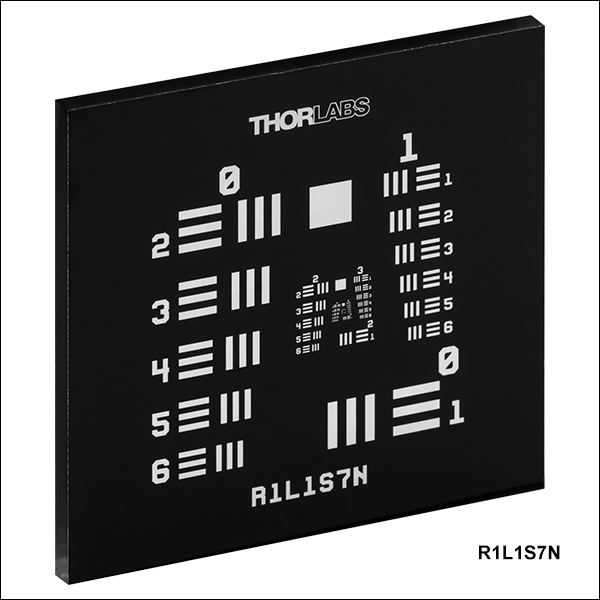
| R1L1S7P | 8 | 0 to +7 | Single Set | 1" x 1" |
| R1L1S7N | ||||
| R2L2S4P | 1.5" x 1.5" | |||
| R2L2S4N | ||||
| R3L1S4P1 | 3" x 1" | |||
| R3L1S4N1 | ||||
| R3L1S4P | 6 | +2 to +7 | Wheel | |
| R3L1S4N | ||||
| R3L1S4PR | ||||
| R3L1S1B | 0 to +5 | Single Set | ||
| R3L3S1P | 10 | -2 to +7 | Single Set | 3" x 3" |
| R3L3S1N | ||||
| R3L3S1PR | ||||
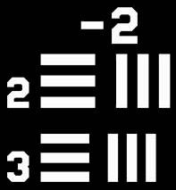
图2.2 线集示例
分辨率靶有一系列水平和垂直线,用于确定成像系统分辨率。一组内有六个元素(水平和垂直线对),十组构成分辨率图案。图2.2展示分辨率靶上-2组的2和3元素。
这些测试靶以三条线为一个集合,提高识别伪分辨率的能力。当线集太模糊使重叠部分看似形成了倒立的更清晰的线,伪分辨率就会发生。这可能误读光学系统分辨率,因为线看似能够分辨。伪分辨率也会使线集中看似少一条线。由于三条线和两条线的差异相比五条线和四条线的差异更容易被发现,因此测试靶以三条线为一个集合更容易识别伪分辨率。
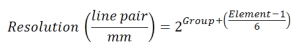
每个元素中的线距等于线宽。当测试靶成像后,通过观察水平和垂直线的清晰度确定成像系统分辨率。最大的不可分辨的水平线和垂直线确定成像系统的分辨能力。表2.4列出根据下式计算的每组中每个元素的lp/mm数值。我们分辨率测试靶的最大分辨率为228.0 lp/mm,大约4.4 µm/lp。3英寸x3英寸靶从-2到+7共10组;3英寸x1英寸轮式图案具有9个测试靶,每个靶都有从+2至+7组;3英寸x1英寸双折射靶从0至+5共6组;18 mm x 18 mm (0.71英寸x0.71英寸)组合测试靶从+2到+7共六组;Ø1英寸靶从+2到+7共六组。
| Table 2.4 1951 USAF Target Spatial Frequencies | ||||||||||
|---|---|---|---|---|---|---|---|---|---|---|
| Element | Group Number | |||||||||
| -2 | -1 | 0 | 1 | 2 | 3 | 4 | 5 | 6 | 7 | |
| 1 | 0.250 | 0.500 | 1.00 | 2.00 | 4.00 | 8.00 | 16.00 | 32.00 | 64.00 | 128.00 |
| 2 | 0.280 | 0.561 | 1.12 | 2.24 | 4.49 | 8.98 | 17.95 | 36.0 | 71.8 | 144.0 |
| 3 | 0.315 | 0.630 | 1.26 | 2.52 | 5.04 | 10.10 | 20.16 | 40.3 | 80.6 | 161.0 |
| 4 | 0.353 | 0.707 | 1.41 | 2.83 | 5.66 | 11.30 | 22.62 | 45.3 | 90.5 | 181.0 |
| 5 | 0.397 | 0.793 | 1.59 | 3.17 | 6.35 | 12.70 | 25.39 | 50.8 | 102.0 | 203.0 |
| 6 | 0.445 | 0.891 | 1.78 | 3.56 | 7.13 | 14.30 | 28.50 | 57.0 | 114.0 | 228.0 |
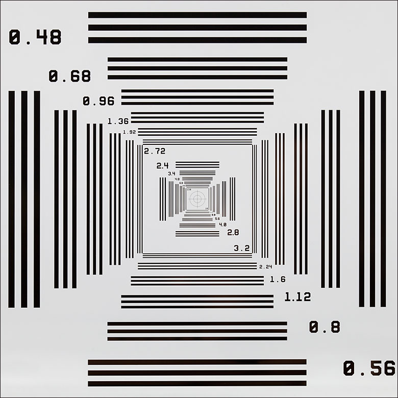
Click to Enlarge
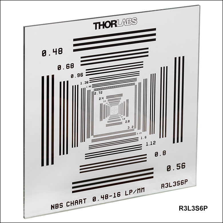
图2.5 R3L3S6P NBS 1952测试靶特写
NBS 1952测试靶
- 可单通扫描
- 以三线一个集合减少伪分辨率
- 提供正靶
- 1英寸x3英寸和3英寸x3英寸
NBS 1952测试靶以三条垂直线或三条水平线为一个集合。每条线及它与相邻线的间距可看作一个线对或一个周期。每个测试靶能够测试的分辨率以lp/mm的频率给出。表2.6给出了我们两个NBS 1952测试靶可用的每个频率以及对应的线宽。
这些测试靶主要优点有二:使伪分辨率降至最少,可以单通扫描。当线集太模糊使重叠部分看似形成了倒立的更清晰的线,伪分辨率就会发生。这可能误读光学系统分辨率,因为线看似能够分辨。伪分辨率也会使线集中看似少一条线。由于三条线和两条线的差异相比五条线和四条线的差异更容易被发现,因此测试靶以三条线为一个集合更容易识别伪分辨率。
通过排布这些测试靶的线集可能获得单通扫描优势。水平和垂直线集以相同样式、相同频率排列,使测试靶沿从左上到右下的一条对角线对称。如果从左到右或从上到下扫描测试靶,到达中心前线频率一直增大,然后从另一边下降。无论是水平还是垂直扫描,单次通过整个图案将覆盖测试靶上的每个频率。因此只要以单向运动就能确定光学系统的分辨率。
| Table 2.6 NBS 1952 Target Spatial Frequencies | |||||||
|---|---|---|---|---|---|---|---|
| Resolution (lp/mm) | Line Width (µm) | Resolution (lp/mm) | Line Width (µm) | Resolution (lp/mm) | Line Width (µm) | Resolution (lp/mm) | Line Width (µm) |
| 0.48 | 1041.7 | 2.24 | 223.2 | 6.8 | 73.5 | 20 | 25 |
| 0.56 | 892.9 | 2.4 | 208.3 | 8 | 62.5 | 24 | 20.8 |
| 0.68 | 735.3 | 2.72 | 183.3 | 9.6 | 52.1 | 28 | 17.9 |
| 0.8 | 625 | 2.8 | 176.8 | 11.2 | 44.6 | 34 | 14.7 |
| 0.96 | 520.8 | 3.2 | 156.3 | 12 | 41.7 | 40 | 12.5 |
| 1.12 | 446.4 | 3.4 | 147.1 | 13.6 | 36.8 | 48 | 10.4 |
| 1.36 | 367.6 | 4 | 125 | 14 | 35.7 | 56 | 8.9 |
| 1.6 | 312.5 | 4.8 | 104.2 | 16 | 31.3 | 68 | 7.4 |
| 1.92 | 260.4 | 5.6 | 89.3 | 17 | 29.4 | 80 | 6.3 |
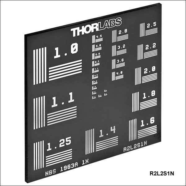
NBS 1963A测试靶
- 提供正靶、负靶和双折射靶
- 高频选项
- 2英寸x2英寸专用测试靶,1英寸x3英寸组合靶
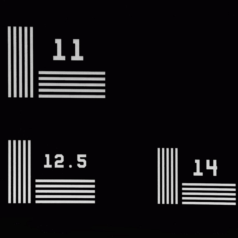
NBS 1963A靶以五条垂直线或五条水平线为一个集合。每条线及它与相邻线的间距可看作一个线对或一个周期。每个测试靶能够测试的分辨率以cycles/mm的频率给出。在Thorlabs的NBS 1963A测试靶上,每个线集都标有频率。确定可分辨的最小线(最高的cycles/mm数值)就可确定成像系统分辨率。
我们的标准NBS 1963A测试靶提供26个线集,分辨率从1.0 cycles/mm到18.0 cycles/mm。对于更严格的分辨率测试,我们的高频NBS 1963A测试靶具有48个线集,频率从1.0 cycles/mm到228 cycles/mm,而我们的R1L3S5P分辨率和畸变组合靶具有35个线集,频率从4.5 cycles/mm到228 cycles/mm。周期是频率的倒数,表2.8中给出了所有频率及其相应的周期。至于单独的线宽,周期除以2即可。
| Table 2.8 NBS 1963A Target Spatial Frequencies | |||||||
|---|---|---|---|---|---|---|---|
| Cycles/mm | Cycle Size | Cycles/mm | Cycle Size | Cycles/mm | Cycle Size | Cycles/mm | Cycle Size |
| 1.0 | 1.00 mm | 4.0 | 0.250 mm | 16.0 | 0.063 mm | 64.0 | 0.016 mm |
| 1.1 | 0.909 mm | 4.5 | 0.222 mm | 18.0 | 0.056 mm | 72.0 | 0.014 mm |
| 1.25 | 0.800 mm | 5.0 | 0.200 mm | 20.0 | 0.05 mm | 81.0 | 0.012 mm |
| 1.4 | 0.714 mm | 5.6 | 0.179 mm | 23.0 | 0.043 mm | 91.0 | 0.011 mm |
| 1.6 | 0.625 mm | 6.3 | 0.159 mm | 25.0 | 0.040 mm | 102 | 0.010 mm |
| 1.8 | 0.556 mm | 7.1 | 0.141 mm | 29.0 | 0.034 mm | 114 | 0.009 mm |
| 2.0 | 0.500 mm | 8.0 | 0.125 mm | 32.0 | 0.031 mm | 128 | 0.008 mm |
| 2.2 | 0.455 mm | 9.0 | 0.111 mm | 36.0 | 0.028 mm | 144 | 0.007 mm |
| 2.5 | 0.400 mm | 10.0 | 0.100 mm | 40.0 | 0.025 mm | 161 | 0.0062 mm |
| 2.8 | 0.357 mm | 11.0 | 0.091 mm | 45.0 | 0.022 mm | 181 | 0.0055 mm |
| 3.2 | 0.313 mm | 12.5 | 0.080 mm | 51.0 | 0.020 mm | 203 | 0.0049 mm |
| 3.6 | 0.278 mm | 14.0 | 0.071 mm | 57.0 | 0.018 mm | 228 | 0.0044 mm |
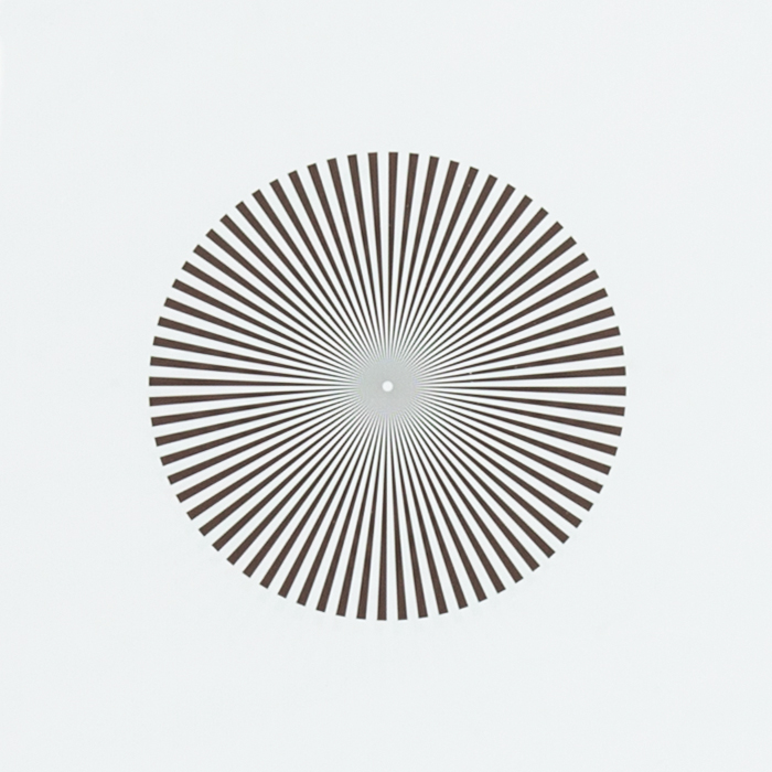
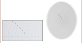
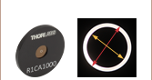
扇形星测试靶
扇形星靶也称西门子星靶,由许多扇形暗条组成,所有暗条以共同的中心向外辐射时宽度逐渐增加。暗条之间的空白区域可看作明条,在任何给定的径向距离内,明条和暗条宽度相同。理论上讲,所有靶条只相交于靶中心。有些扇形星靶,包括本页销售的全部,中心都是切断所有扇形条的空白圆。但是根据用来观察测试靶的成像系统的分辨率,扇形条在距中心一定距离处可能看起来是接触的。通过测量这个距离,用户可以定义光学系统的分辨率。
如要根据到扇形星中心的任意给定径向距离计算分辨率,先计算此半径处线对、明条或暗条的宽度。可以使用下面的弦长公式,其中r是到中心的径向距离。角度Θ是一对明暗靶条覆盖的度数,等于360°除以总的靶条数。计算线对宽度后,就可以知道分辨率,即宽度的倒数。

Thorlabs提供两种专用的扇形星靶(R1L1S2P和R1L1S3P)以及三种包含扇形星图和其它图案的测试靶(R1L3S5P、R1L1S1P和 R1L1S1N)。表2.10概括了每种测试靶的扇形星图案规格。
| Table 2.10 Sector Star Specifications | ||||||
|---|---|---|---|---|---|---|
| Item # | Pattern Type | Sector Star Pattern Outer Diameter | Center Circle Diameter | Number of Bars | Resolution at Outer Diameter | Resolution at Center Circle |
| R1L1S2P | Positive | 10 mm | 200 µm | 36 Over 360° | 1.15 lp/mm | 57.5 lp/mm |
| R1L1S3P | 72 Over 360° | 2.29 lp/mm | 115 lp/mm | |||
| R1L1S2N | Negative | 36 Over 360° | ||||
| R1L1S3N | 72 Over 360° | |||||
| R1L3S5P | Positive | 2 mm | 100 µm | 36 Over 360° | 5.75 lp/mm | 115 lp/mm |
| R1L1S1P | Positive | 2 mm | 20 µm | 36 Over 360° | 5.75 lp/mm | 575 lp/mm |
| R1L1S1N | Negative | |||||
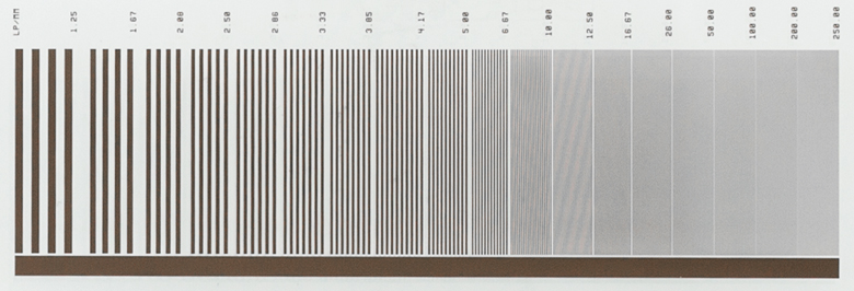
可变线栅
线栅是一组平行暗线,线宽等于线距。在任意线栅中,一条暗线和一个空白部分组成一个线对。光学系统的分辨率取决于它能区分相邻线对的能力。因此,线栅分辨率定义为给定空间内的线对数,一般以线对每毫米(lp/mm)表示。可变线栅有很多分区,从一个分区到下一个分区的分辨率增加或降低。通过识别光学系统能够分辨的最高线栅分辨率,用户就能确定系统分辨率。
Thorlabs提供各种可变线栅,分辨率范围从1.25 lp/mm到250lp/mm。表2.12给出了所含分辨率与线对尺寸的转换关系。
| Table 2.12 Spatial Frequency to Resolution Conversion | |||||
|---|---|---|---|---|---|
| lp/mm | Line Pair Size | lp/mm | Line Pair Size | lp/mm | Line Pair Size |
| 1.25 | 0.80 mm | 3.85 | 0.26 mm | 16.67 | 0.06 mm |
| 1.67 | 0.60 mm | 4.17 | 0.24 mm | 50 | 0.02 mm |
| 2.08 | 0.48 mm | 5.0 | 0.20 mm | 100 | 0.01 mm |
| 2.5 | 0.40 mm | 6.67 | 0.15 mm | 200 | 0.005 mm |
| 2.86 | 0.35 mm | 10.0 | 0.10 mm | 250 | 0.004 mm |
| 3.33 | 0.30 mm | 12.5 | 0.08 mm | - | - |
Click to Enlarge
上图显示了正负测试靶使用的钠钙玻璃透过率。它并不代表R3L1S1B双折射1951 USAF测试靶中使用的钠钙玻璃。


Click to Enlarge
上图显示了R3L1S1B双折射靶的样本透过率曲线,包括玻片、盖板玻璃和双折射液晶聚合物层。
Click to Enlarge
上图显示了10 mm厚的N-BK7样品的透过率,此材料用于R2L2S1B双折射靶的基底和盖板。
Jason Williamson
General Manager
Thorlabs Spectral Works
需要报价?
| Customization Parameters | ||
|---|---|---|
| Substrate Sizea | Min | 8 mm x 8 mm (5/16" x 5/16") |
| Max | 85 mm x 85 mm (3.35" x 3.35") | |
| Substrate Materials | Soda Lime Glass UV Fused Silica Quartz | |
| Coating Material | Chromeb Low-Reflectivity Chromec | |
| Coating Optical Density | ≥3d or ≥6e @ 430 nm | |
| Minimum Pinhole/Spot | Ø1 µm | |
| Minimum Line Width | 1 µm | |
| Line Width Tolerance | -0.25 / +0.50 µm | |
| Maximum Line Density | 500 lp/mm | |
定制OEM测试靶和分划板
我们拥有光刻设计和生产能力,能够制造一系列图案化的光学器件。我们在南卡罗来纳州哥伦比亚市的Thorlabs光谱产品工厂生产测试靶、网格畸变测试靶和分划板。 这些器件广泛用于显微镜、成像系统和光学对准装置等应用。
除了测试靶和分划板标准品现货之外,我们还可以定制钠钙玻璃、紫外熔融石英或石英基底上的镀铬图案,适用的基底尺寸从8 mm x 8 mm至85 mm x 85 mm。 我们也可以基于应用将基底切割成适合的形状。我们通过光刻涂覆工艺能够制作低至1 µm的铬图案特征。图165B到165J是样品图例,可以制成正图案或负图案,如图165A所示。
如需定制测试靶和分划板报价,请联系技术支持techsupport-cn@thorlabs.com。
样品图例
 Click to Enlarge
图165E:二进制样品图
 Click to Enlarge
图165D:同心圆样品图
 Click to Enlarge
图165C:十字线样品图
 Click to Enlarge
图165B:网格样品图
 Click to Enlarge
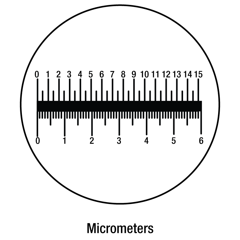
图165J:千分尺样品图
 Click to Enlarge
图165H:针孔样品图
 Click to Enlarge
图165G:量角器样本图案
 Click to Enlarge
图165F:刻度样品图
示例应用
- 蚀刻分划板
- 灰度掩模
- 分辨率分划板
- 诊断分划板
- 休闲镜
- 开槽分划板
- 目镜刻度
- 十字形照明
- 阻挡靶
- 双目镜分划板
Click to Enlarge
图165A:正和负十字样本图案
此标签详细介绍了由我们工程师开发的良好清洁技术,以清洁分划板、测试靶、畸变靶和校准靶。
清洁过程
- 使用干净的湿海绵(最好由聚乙烯醇(PVA)制成)和洗洁精,轻轻擦拭分划板或测试靶的正反面。
- 用水冲洗分划板或测试靶。
- 通过干净干燥的空气吹干,或在干净表面风干分划板或测试靶。
我们不建议使用毛巾、布或者纸巾擦干表面。如果仍存在污染物,请将分划板或测试靶浸泡在清洁剂和水溶液中一个小时,必要时可重复此步骤。
| Posted Comments: | |
Wenbo Yan
(posted 2025-06-24 22:29:04.43) Hi Team,
Could you please provide a high-resolution image of the R1DS1N1?
I need to compare the image and the original image to get an analysis to the imaging system.
Best regards,
Wenbo EGies
(posted 2025-07-01 06:36:11.0) Thank you for contacting Thorlabs. I have reached out to you directly regarding this. Daniel Penagos
(posted 2024-11-07 01:01:26.553) Hi, Could you guys offer a 1inch 1951 USAF target for reflection too? Currently this only possible in the 3x1 format, not the 1inch one. cdolbashian
(posted 2024-11-12 11:42:02.0) Thank you for reaching out to us with this inquiry. We have both positive and negative test targets in the 1"x1" format as well as the 1" round format. I am not sure exactly what kind of target you are looking for in this sense. I have contacted you directly to discuss your application and requirements. Moshe Peleg
(posted 2024-11-07 17:02:26.517) Hello,
I have this product in the lab. What is its error percentage? cdolbashian
(posted 2024-11-12 09:19:17.0) Thank you for reaching out to us with this inquiry. For the target R1L3S6PR, we have measured an error in center-to-center position of features of +/-100nm, and an error in width/dimension of features on the order of +/-500nm. Gyeonghun Kim
(posted 2024-10-22 15:01:35.263) Hi, I would like to know the thickness of the Liquid Crystal Polymer layer in the birefringent 1951 USAF test target (R3L1S1B). I understand that each resolution target may have different retardance values. I’m just looking for a ballpark figure. Thanks. cdolbashian
(posted 2024-10-28 09:48:21.0) Thank you for contacting Thorlabs. We process the 1951 USAF Birefringent Resolution Test Targets by controlling the retardance rather than the thickness of the Liquid Crystal Polymer layer. The R3L1S1B has a retardance of approximately 0.5 waves at 532nm. Minh-Chau Nguyen
(posted 2024-06-14 09:11:59.607) Hello,
My name is Minh-Chau Nguyen, R&D engineer at Phasics SA, France. I am writing you in order to consult the characteristics of the birefringent test target R3L1S1B.
I carried out a measurement of the retardance on your test target. The measurement is based on the light intensity while rotating a linear retarder under a polarized incident beam. The retardance is then calculated from the min and max of intensity. From the result, I have some conclusions:
- A significant retardance presents on the whole test target (inside and outside the pattern).
- The measured retardance is close to the data announced by Thorlabs. The difference of retardance is relatively small between the pattern and the surrounding zone.
- The difference between the pattern and the surrounding zone is mostly on the angle of fast-axis (Δθ ≈ 33°), which is not mentioned in the description.
Can you please validate my method of measurement as well as the result on the retardance and the angle of fast-axis, since it is not clearly mentioned in the description?
I am looking forward to hearing from you soon. Thank in advance.
Yours sincerely,
Minh-Chau Nguyen cdolbashian
(posted 2024-07-01 04:29:26.0) Thank you for contacting Thorlabs. The retardance of entire test target can be slightly non-uniform, as usually this R3L1S1B is used as a visual resolution tool. The typical fast axis angle of background and pattern is 0 degree and 45 degrees respectively. Again, as a visual tool, the retardance and axis angle are not tightly controlled and may vary from lot to lot. A Babinet Compensator is used for retardance measurement during production process, the intensity measurement approach you mentioned is a common method for retardance testing, it should also be feasible. Yudong Fan
(posted 2024-05-21 21:03:23.003) The .step file and solidwork file are not valid cdolbashian
(posted 2024-05-24 02:45:45.0) Thank you for reaching out to us. I have contacted you directly to inquire regarding the problems you are having with the step files. Michael Tan
(posted 2024-04-16 15:05:28.9) Hi, I would like to check if there is the same negative target but with smaller diameter available for purchase? ksosnowski
(posted 2024-04-22 04:20:33.0) Hello Michael, thanks for reaching out to Thorlabs. We have offered some custom patterns and sizes before. I have reached out directly to discuss your application in further detail. luo kun
(posted 2023-12-04 16:23:03.573) group 2-7中1-6分别对应多少lp/mm cdolbashian
(posted 2023-12-11 10:44:00.0) Thank you for reaching out to us with this inquiry. All information regarding the line spacing and frequency is outlined on the product page above. Additionally, as this is an industry standard test target pattern, 1951 USAF test target, additional information can be found on the web. I have linked you to some of these resources via email. Louise Baehr
(posted 2022-10-26 11:59:29.04) Dear Sir or Madam,
I am sorry to bother you. I would like to have more information on how you calculated the outer and inner frequency of your Siemens star target.
Indeed, when I use your formula, taking 72 bars and so theta = 360°/72 = 5 and the outer diameter of 10mm, I get:
c = 2 * 10mm * sin(5°/2) = 0.8724 mm
resolution = 1 / 0.8724 = 1.1463 lp/mm
BUT, in your table, you indicate a frequency of 2.29 lp/mm at the outer diameter. Could it be possible to have the details of your calculations ? It seems I'm missing something and I really need to understand.
Thank you very much and sorry again for bothering you.
Best regards cdolbashian
(posted 2022-10-31 01:52:36.0) Thank you for reaching out to us! I think perhaps you may be overlooking the negative space between each feature. The size of each line pair should be considered in the 72 segments. Simply take the number of line pairs (72) and divide by the circumference of the circle (2*Pi*5mm~31mm). Taking this quotient (72/31mm) yields ~2.29lp/mm. I have contacted you directly to address this further. Kimi Huang
(posted 2022-02-17 16:32:57.09) Hi Sir,
A question about Reflectivity of pattern and clear area.
Would like to check the Reflectivity % of pattern is ? in the plot, it looks have high R% of pattern? but not make sense to me becuase pattern is black pattern. So I think I misunderstand something here.
So, the question is : what is the Reflectivity of Pattern and clear I should use in the model?
Thanks cdolbashian
(posted 2022-02-18 05:09:16.0) Thank you for reaching out to us Kimi. The substrate of the R1DS1P is soda lime glass, while the pattern is made with anti-reflective chrome. The reflectivity of the chrome and the transmission of the soda lime, can be found on the "Graphs" tab on this page. You can approximate the reflectivity of the soda lime glass as 1-Transmission at a given wavelength, but for a true reflectivity value, one must also consider the absorption of the soda lime substrate. I have reached out to you directly to discuss this further in context of your particular light source. Ulrich Leischner
(posted 2021-11-03 07:47:52.73) I need the precise values of the lines in this target. the value LP/mm is not completely clear. Is this the full diameter of 3 lines, or is this the periodic length (full diameter of 2 lines, a negative and a positive one)
A drawing with the values in the PDF would be very helpful.
Regards jgreschler
(posted 2021-11-12 04:45:20.0) Thank you for reaching out to Thorlabs. The definition of line pairs per millimeter (lp/mm) is defined by a pair of lines, one bright and one dark, in a given spacing. For example, if the specification is 1 lp/mm, that means that the coated line is 0.5mm and the uncoated line is 0.5mm. You can read more about this definition in our Resolution Targets tab at the top of the product page, further literature can be found here https://en.wikipedia.org/wiki/1951_USAF_resolution_test_chart Fidel Vega
(posted 2021-10-11 04:24:48.963) Dear Sir or Madam,
We are interested in buying some customized reticles & calibration tests. I would need to contact your technical department to ask some questions about the features of the items that we need. The 1st October I sent a message to TSW@thorlabs.com with this request, but I have not yet received any feedback from your side.
Thank you
Fidel cdolbashian
(posted 2021-12-23 11:38:58.0) Thank you for contacting us here at Thorlabs! We apologize deeply for our lack of communication. We have reached out to you directly to discuss your custom. Andrew Keys
(posted 2021-08-19 12:14:32.71) I recently ordered a positive and negative version of the R1L1S1P Resolution and Distortion Target. To be able to precisely navigate around the elements on this target, I ordered a XYF1 mount. Upon receipt, I now realize that the 18mm x 18mm target cannot easily be mounted in the XYF1 without covering much of the target elements. What is the recommended method of mounting these R1L1S1P targets? cdolbashian
(posted 2021-08-27 09:29:10.0) Thank you for reaching out to us here at Thorlabs! The test target you have selected is intended for use with a standard microscopy system, rather than free space optics. Because this is the case, using it with the XYF1 may result in the obscuration of some of the edges of the test pattern, due to the size of the target. I have reached out to you directly with alternative solutions. We are always hungry for feedback, so we appreciate you bringing this incompatibility of seemingly-compatible parts to our attention. moti yanuka
(posted 2021-02-17 20:19:35.317) I am interested in resolution and distortion targets, could you send to me quotations? YLohia
(posted 2021-02-17 10:20:33.0) Hello, thank you for your interest in our products. Quotes can be requested by contacting our Sales Team (sales@thorlabs.com) or by adding the items to your cart and clicking "Request a Quote" button on your cart page. Ananth Rao
(posted 2020-09-15 06:34:45.553) Hi ,
We have bought this resolution target R1L1S1N, there are two peculiar questions,
1. What is methodology to clean the target? Is there any documentation?
2. What is the surface flatness of the target? YLohia
(posted 2020-09-16 10:32:26.0) Hello, thank you for contacting Thorlabs. Unfortunately, we don't have specific documentation on cleaning the R1L1S1N. That being said, we do have a general optics cleaning guide here: https://www.thorlabs.com/newgrouppage9.cfm?objectgroup_id=9025. I have reached out to you directly to discuss your request. wen cao
(posted 2020-06-24 09:12:46.36) 这个分辨率板是透明的吗?可以背光照射吗? YLohia
(posted 2020-06-24 09:15:24.0) Thank you for contacting Thorlabs. An applications engineer from our team in China (techsupport-cn@thorlabs.com) will reach out to you directly. 程访 许
(posted 2019-11-26 16:41:58.167) 此产品镀的铬膜,对633nm的光,反射率是多少?望回复,我在产品介绍中没看到,最近课题组购买了此产品,我需要这个参数。 nbayconich
(posted 2019-12-03 04:04:53.0) Thank you for contacting Thorlabs. Although we do not specify a guaranteed reflectivity of this chrome coating, the reflectivity will be about 25% at 633nm. I will reach out to you directly. Soocheol Kim
(posted 2019-11-19 21:33:39.29) Dear Sir/Madame,
I checked the retardation of the entire target, which was to be 280±20 nm.
Is this retardation a retardation between the entire target and the patterned area?
I'd like to know the retardation between the entire target and the patterned area. nbayconich
(posted 2019-11-25 10:35:23.0) Thank you for contacting Thorlabs. The R2L2S1B is a half wave plate for 546 nm (or 273nm @546nm). The entire target has the same retardance, the pattern is created by having a 45 deg azimuth difference against the background. Anne De Paepe
(posted 2019-11-06 10:27:10.69) Dear Sir/Madam,
I am looking for a spatial resolution test for my Raman microscope (532nm, 633nm and 785nm lasers). Where I worked before we had a USAF target of Si on Quartz but not sure if this is the best one. What would you recommend?
Thank you YLohia
(posted 2019-11-08 10:51:17.0) Hello, thank you for contacting Thorlabs. Our Chrome on Glass targets are suitable for all wavelengths mentioned by you. Ultimately, the use comes down to personal preference, availability, and possible requirements on transmission/reflectivity. I have reached out to you directly to gain a better sense of your needs. Soojung Kim
(posted 2019-11-05 08:24:52.273) Hello.
How thick is the patterned chrome on R1L1S1P test target? It's very important point to test axial resolution of our equipment.
Sincerely. YLohia
(posted 2019-11-05 10:46:52.0) The thickness of the chrome layer on our targets is 0.120 µm. More information can be found in the specs table in the Overview tab. Fernando Brandi
(posted 2019-08-13 08:52:46.3) Dear Sir/Madame,
I am interested in you R2L2S1B Birefringent NBS 1963A Resolution Target, 2" x 2" for testing a polarizing imaging system.
For our porpoises we need to use both fundamental 1064 nm and second harmonic 532 nm laser light.
In order to evaluate the use of the R2L2S1B Birefringent NBS 1963A Resolution Target for our application I need to know the total optical path length of the target at the two wavelength (1064 nm and 532 nm) and for both ordinary and extraordinary polarization orientation.
Looking forwrd for your reply I thank you for the attention.
Kind regards,
Fernando Brandi, PhD
Consiglio Nazionale delle Ricerche (CNR)
Istituto Nazionale di Ottica (INO)
Sede Secondaria "A. Gozzini" di Pisa
Via Moruzzi 1, 56124-Pisa, Italy
Tel. +39 050 315 2584
Fax. +39 050 315 2247
E-Mail: fernando.brandi@ino.cnr.it
http://research.ino.it/Groups/ilil/it/about_it/ YLohia
(posted 2019-08-28 03:45:30.0) Hello Fernando, thank you for contacting Thorlabs. The design wavelength for half-wave retardance for the R2L2S1B is 546nm. The liquid crystal delta(n) is 0.1555 at 550 nm. Unfortunately, we do not have the data for your exact operating wavelengths. We reached out to you directly to discuss this further. user
(posted 2019-07-01 11:43:13.403) What mechanical mount do you suggest to hold R1L1S1P or R1L1S1N? YLohia
(posted 2019-07-01 12:19:11.0) Hello, thank you for contacting Thorlabs. We recommend the XF50, PC2, FH2, SFH2, CH1A, or FP01 mounts for these targets. Robert Standaert
(posted 2019-05-13 16:45:12.813) High-resolution or vector images of the targets would be very helpful. YLohia
(posted 2019-05-14 10:10:55.0) Hello, thank you for your feedback! We are in the process of discussing the possibility of publishing this information on our website. sureshbil67
(posted 2018-08-11 07:29:46.71) I want to know resolution target patterns specification of Night vision devices YLohia
(posted 2018-09-17 09:59:01.0) Hello, thank you for contacting Thorlabs. I have reached out to you directly to discuss your application in more detail. haolin.zhang
(posted 2018-05-09 20:12:29.3) I am using the R2L2S1B Resolution Target to implement a holographic experiment. Could you please provide me the refractive index of the liquid crystal polymer layer aligned in the target, please? Also, could you please provide the information about the material of this liquid crystal polymer layer? Thanks in advance. YLohia
(posted 2018-05-11 08:39:33.0) Hello, thank you for contacting Thorlabs. Unfortunately, we cannot disclose this information since it is proprietary. ayoub.mghari
(posted 2017-11-29 11:27:24.9) I am interested in ordering this target but I have the following question:
My understanding is that the target is made out of Chrome coating on Soda Lime Glass. This, due to a given illumination system will result in shadows on the rear side, correct?
Is it possible to have this target on a non-transparent glass?
Please send me a Quote by E-mail. nbayconich
(posted 2017-12-27 04:07:26.0) Thank you for contacting Thorlabs. You are correct if using the positive resolution targets then light incident on the front of the target light will reflect off of the chrome patterns. The negative targets have clear patterns with chrome coating the rest of the substrate which makes these intended for back lit applications. We can provide custom targets with non-transparent substrate such as opal. I will reach out to you directly to discuss our custom target capabilities. miguel.pleitez
(posted 2017-05-24 13:59:18.767) would it be possible to get this test targets but on a ZnSe substrate instead of glass? I would be very interested on them. Let me know.
Thanks in advance. nbayconich
(posted 2017-06-13 09:48:26.0) Thank you for contacting Thorlabs. I will contact you directly about our custom capabilities. yoonys
(posted 2016-12-06 01:07:03.37) It'd be helpful to draw what "line pair" is on the website, like Figure 1(b) in the following link.
http://www.edmundoptics.com/resources/application-notes/imaging/resolution/ tcampbell
(posted 2016-12-15 11:47:36.0) Response from Tim at Thorlabs: Thank you for your feedback. We will look into adding a diagram explaining line pairs and camera resolution soon. theodore_morse
(posted 2016-11-16 11:49:07.157) I wish to use a blue laser (266 nm) to get the
resolution. In the masks that you use, will it transmit blue light?
I would prefer it to be a quartz substrate.
Ted Morse
Prof. (Research)
School of Engineering
Brown University
Providence, RI 02912 tfrisch
(posted 2016-11-18 10:32:42.0) Hello Ted, thank you for contacting Thorlabs. I am checking on the transmission and reflection of the chrome and soda lime in UV regions now. I will contact you directly when I have more information. user
(posted 2014-06-02 12:59:19.84) What is the line width of the grids on the R1L1S1P resolution target? jlow
(posted 2014-06-03 10:41:23.0) Response from Jeremy at Thorlabs: The grid line width is 5µm for both the 100µm and 50µm grids, and 1.5µm for the 10µm grid. pnon
(posted 2012-12-24 11:58:00.0) Response from Pauline at Thorlabs: The masks used for our test targets are calibrated to NIST-traceable standards. We use contact photolithography with a mask aligner to define the pattern on the glass substrate. Once the pattern is defined, we chemically etch the substrates to produce the finished targets. Although similar in performance with the mask, we do not provide NIST traceable certificates. I will contact you shortly to provide information in getting targets with NIST certificates. mmarcoux
(posted 2012-12-17 10:05:40.897) Are the R1L3S3P distortion targets N.I.S.T. certified/traceable? tcohen
(posted 2012-06-18 10:51:00.0) Response from Tim at Thorlabs: Information on this question was provided for a previous request @400nm below: “The reflectivity of dark pattern on reticle is less than 12% @400nm. For the white pattern, it is just sodium lime glass, so the reflectivity is estimated to be ~ 3.5% @ 400nm ( assuming refractive index is ~ 1.463).” I have contacted you to find out your wavelength and to see if you require more information. cooljkpark
(posted 2012-06-15 07:09:36.0) Can you tell me the reflection coefficient of glass and chrome in your resolution target? bdada
(posted 2012-06-05 19:09:00.0) Response from Buki at Thorlabs to marctessier:
Thank you for participating in our feedback forum. We are developing some new crossed reticles and we have contacted you for a drawing of the custom reticle you need.
We have an office in France and the information is included on the web page linked below that lists our offices and distributors world wide:
http://www.thorlabs.de/Distributors.cfm marctessier
(posted 2012-06-05 17:31:41.0) Hello,
I'm working in Rillieux la Pape, near Lyon, in France, and I must find a custom 1" crossed reticle. I've a PDF file showing it.
I need only one part.
Are you able to supply such good?
Do you have a french retailer?
Best regards,
Marc bdada
(posted 2012-02-27 17:34:00.0) Response from Buki to dick.verhaart:
For our reticle products, we use chrome with O.D.=>3.0 @430nm. The reflectivity of dark pattern on reticle is less than 12% @400nm. For the white pattern, it is just sodium lime glass, so the reflectivity is estimated to be ~ 3.5% @ 400nm ( assuming refractive index is ~ 1.463).
Please contact TechSupport@thorlabs.com if you have any questions. bdada
(posted 2012-02-24 18:46:00.0) Response from Buki at Thorlabs to dick.verhaart:
Thank you for your feedback. We are looking into this and will contact you shortly with more information and post an update here. dick.verhaart
(posted 2012-02-02 05:48:19.0) Can this product (R3L3S1P/N) be used with 405 nm reflective illumination? I find with similar products from other suppliers that the reflection contrast, at this wavelength, between glass and chrome is very small, contrast reversal may occur. Does Thorlabs specific refelctivity of "black"and "white"at 405 nm? bdada
(posted 2011-08-01 14:14:00.0) Response from Buki at Thorlabs:
We measured the smallest grid pattern (10um) of R1L2S2P using a micrometric system, OLYMPUS MX50, and the tolerance of the pattern is < +/-0.1um. Please contact TechSupport@thorlabs.com with additional questions. ajh
(posted 2011-07-26 03:05:25.0) Can you provide specifications for the accuracy of the graduations on your stage micrometers, R1L2S2P and R1L2S1P? I assume they are very accurate but when calibrating image scale you do want to know how accurate your calibrator is. user
(posted 2011-01-31 10:50:15.0) Response from Buki to Paul. Thank you so much for your feedback. We are expanding our selection of reticles and will make them more compatible with our cage system. We will contact you directly to learn how we can better meet your needs. paul
(posted 2011-01-24 12:02:31.0) I am surprised (given the sophistication of your product line)you do not stock reticles that can be used with the cage plate systems. I currently buy reticles elsewhere and then mount them in cage plates. |

 放大
放大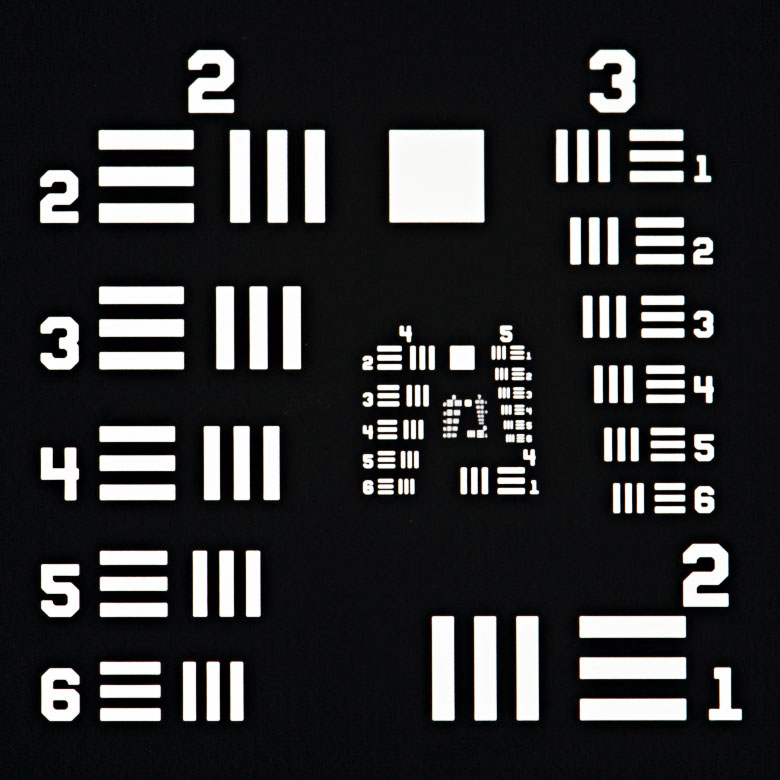
| Optical Specifications | ||||||
|---|---|---|---|---|---|---|
| Item # | R1DS1P1 | R1DS1N1 | R1DS1P | R1DS1N | R1DS1P2 | R1DS1N2 |
| Pattern | LRa Chrome | Clear | LRa Chrome | Clear | LRa Chrome | Clear |
| Background | Clear | LRa Chrome | Clear | LRa Chrome | Clear | LRa Chrome |
| Surface Flatness | < 50 µm | < 15 µm | ||||
| Chrome Optical Densityb | ≥3.0 | |||||
- Ø1英寸(25.4 mm)测试靶,用于Ø1英寸透镜套筒的对准
- 确定光学系统的分辨率
- 符合MIL-S-150A标准
- 提供正靶和负靶
- 三线一集合使伪分辨率最小化
Thorlabs提供Ø1英寸(25.4 mm)正负分辨率测试靶,通过在钠钙玻璃基底上镀低反射、真空溅射铬制成。这些测试靶包含6组(+2到+7)或8组(0到+7)图案,每组6个元素,最大分辨率为228.0线对/毫米(一条亮线和一条暗线)。我们也提供包含9个1951 USAF测试靶的轮式图案,每个靶包含6组(+2到+7)图案。关于1951 USAF图案信息,请看上面的分辨率测试靶标签。
由于这些测试靶以三条线为一个集合,因此能够降低伪分辨率的发生概率,防止不准确的分辨率测量结果。关于伪分辨率的更多信息,请看分辨率测试靶标签。
以P、P1和P2结尾的正测试靶产品型号在透明基底上镀低反射铬图案,适合前照和普通应用。另外,以N、N1和N2结尾的负测试靶产品型号在基底上镀相同的低反射铬膜,使图案部分透明,适合背照和高亮照明应用。

 放大
放大| Optical Specifications | ||
|---|---|---|
| Item # | R1L1S7P | R1L1S7N |
| Pattern | LRa Chrome | Clear |
| Background | Clear | LRa Chrome |
| Surface Flatness | ≤15 µm | |
| Chrome Optical Densityb | ≥3.0 | |
- 1英寸 x 1英寸(25.4 mm x 25.4 mm)测试靶,用于测量整个图像的分辨率
- 确定光学系统的分辨率
- 符合MIL-S-150A标准
- 提供正靶和负靶
- 三线一集合使伪分辨率最小化
Thorlabs提供1英寸 x 1英寸(25.4 mm x 25.4 mm)正负分辨率测试靶,通过在钠钙玻璃基底上镀低反射、真空溅射铬制成。这些测试靶包含8组(0到+7)图案,每组6个元素,最大分辨率为228.0线对/毫米(一条亮线和一条暗线)。更多关于1951 USAF图案的信息,请看上面的分辨率测试靶标签。
由于这些测试靶以三条线为一个集合,因此能够降低伪分辨率的发生概率,防止不准确的分辨率测量结果。关于伪分辨率的更多信息,请看分辨率测试靶标签。
R1L1S7P正测试靶在透明基底上镀低反射铬图案,适合前照和普通应用。另外,R1L1S7N负测试靶在基底上镀相同的低反射铬膜,使图案部分透明,适合背照和高亮照明应用。

 放大
放大| Optical Specifications | ||
|---|---|---|
| Item # | R2L2S4P | R2L2S4N |
| Pattern | LRa Chrome | Clear |
| Background | Clear | LRa Chrome |
| Surface Flatness | ≤15 µm | |
| Chrome Optical Densityb | ≥3.0 | |
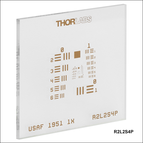
- 1.5英寸 x 1.5英寸(38.1 mm x 38.1 mm)测试靶,用于测量整个图像的分辨率
- 确定光学系统的分辨率
- 符合MIL-S-150A标准
- 提供正靶和负靶
- 三线一集合使伪分辨率最小化
Thorlabs提供1.5英寸 x 1.5英寸(38.1 mm x 38.1 mm)正负分辨率测试靶,通过在钠钙玻璃基底上镀低反射、真空溅射铬制成。这些测试靶包含8组(0到+7)图案,每组6个元素,最大分辨率为228.0线对/毫米(一条亮线和一条暗线)。更多关于1951 USAF图案的信息,请看上面的分辨率测试靶标签。
由于这些测试靶以三条线为一个集合,因此能够降低伪分辨率的发生概率,防止不准确的分辨率测量结果。关于伪分辨率的更多信息,请看分辨率测试靶标签。
R2L2S4P正测试靶在透明基底上镀低反射铬图案,适合前照和普通应用。另外,R2L2S4N负测试靶在基底上镀相同的低反射铬膜,使图案部分透明,适合背照和高亮照明应用。

 放大
放大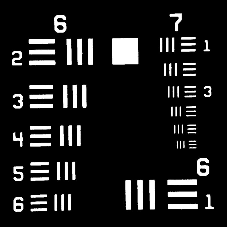
Click to Enlarge
图G4.1 R3L1S4N负测试靶上最小组(6和7)的显微镜图像
- 3英寸 x 1英寸(76.2 mm x 25.4 mm)测试靶,用于测量整个图像的分辨率
- 确定光学系统的分辨率
- 符合MIL-S-150A标准
- 提供正靶、负靶以及反射式正靶
- 通过MLS203P2载玻片支架兼容我们的MLS203显微镜位移台
Thorlabs提供3英寸 x 1英寸(76.2 mm x 25.4 mm)正负分辨率测试靶,通过在钠钙玻璃基底上镀低反射、真空溅射铬制成。单个靶(R3L1S4P1和 R3L1S4N1)有8组(0到+7)图案,每组6个元素。轮式图样靶(R3L1S4P、R3L1S4N和R3L1S4PR)包含9个USAF 1951测试靶,每个6组(+2到+7)图案。两种靶的最大分辨率均为228.0线对/毫米(一条亮线和一条暗线)。关于1951 USAF图案信息,请看上面的分辨率测试靶标签。
| Optical Specifications | |||||
|---|---|---|---|---|---|
| Item # | R3L1S4P1 | R3L1S4N1 | R3L1S4P | R3L1S4N | R3L1S4PR |
| Pattern | LRa Chrome | Clear | LRa Chrome | Clear | LRa Chrome |
| Background | Clear | LRa Chrome | Clear | LRa Chrome | Chrome |
| Surface Flatness | ≤15 µm | ||||
| Chrome Optical Densityb | ≥3.0 | - | |||
| Chrome Reflectanceb | - | LRa Chrome: <10% br=""> Chrome: >40% | |||
由于这些测试靶以三条线为一个集合,因此能够降低伪分辨率的发生概率,防止不准确的分辨率测量结果。关于伪分辨率的更多信息,请看分辨率测试靶标签。
Thorlabs的R3L1S4P1和R3L1S4P正测试靶在钠钙玻璃上镀低反射铬图案,具有透明钠钙基底背景,适合前照和普通应用。R3L1S4N1和R3L1S4N负测试靶在基底上镀相同的低反射铬膜,使图案部分透明,适合背照和高亮照明应用。R3L1S4PR反射式正测试靶在镀铬背景上镀深色低反射铬膜图案,图案和背景之间的高对比度适用于反射应用。详情请查看曲线图标签。

 放大
放大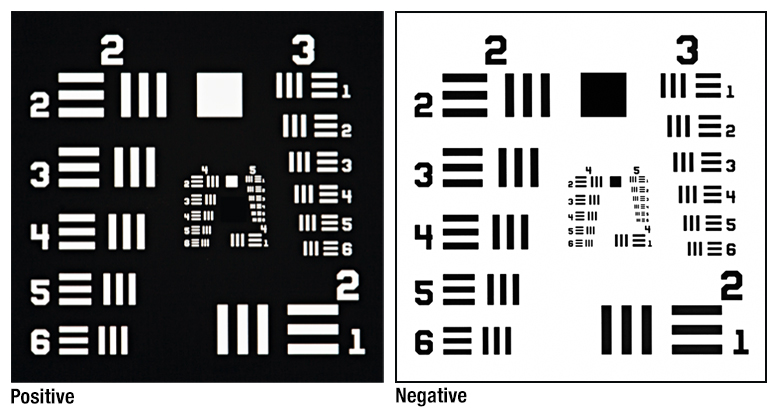
| Optical Specifications | |
|---|---|
| Design | Liquid Crystal Polymer Between Soda Lime Glass Slide and Schott D 263® M Cover Glass |
| Slide Thickness | 1.0 mm (0.04") |
| Cover Slip Thickness | 0.2 mm |
- 确定偏振光学系统的分辨率
- 具有正负图案的双折射测试靶
- 符合MIL-S-150A标准
- 1英寸 × 3英寸(25.4 mm × 76.2 mm)钠钙玻璃基底,带盖玻片
Thorlabs提供1英寸 × 3英寸(25.4 mm x 76.2 mm) 1951 USAF分辨率测试靶,将双折射图样夹在钠钙玻璃片和Schott D 263®† M盖板中间制成。R3L1S1B靶共8组(0 - 7),每组6个元素,最大分辨率为57.0线对/毫米(一条亮线和一条暗线)。只有将靶放在一对正交偏振片之间,才能观察到测试图案,如图G5.1所示。关于测试图案的更多细节,请查看上方分辨率测试靶标签。
通过调节正交偏振片相对测试靶的方向,测试靶可以显示正负两种图样。如果正交偏振片与玻璃四边对齐则成正像。如果正交偏振片与玻璃四边为45°夹角则成负像。
因为对偏振灵敏,这种分辨率测试靶适用于校准和测试双折射成像系统和显微镜、偏振显微镜、Nomarski模式显微镜、偏振成像系统或穆勒矩阵偏振测量仪的分辨率。
† D 263®是Schott AG的注册商标。

 放大
放大| Optical Specifications | |||
|---|---|---|---|
| Item # | R3L3S1P | R3L3S1N | R3L3S1PR |
| Pattern | LRa Chrome | Clear | LRa Chrome |
| Background | Clear | LRa Chrome | Chrome |
| Surface Flatness | ≤15 µm | ≤15 µm | |
| Chrome Optical Densityb | ≥3.0 | - | |
| Chrome Reflectanceb | - | LRa Chrome: < 10% Chrome: >40% | |
- 3英寸x3英寸(76.2 mm x 76.2 mm)测试靶,4.4 µm/lp分辨率
- 确定光学系统的分辨率
- 符合MIL-S-150A标准
- 提供正靶、负靶以及反射式正靶
Thorlabs提供3英寸x3英寸(76.2 mm x 76.2 mm)正负分辨率测试靶,通过在钠钙玻璃基底上镀低反射铬膜制成。3英寸x3英寸靶包含10组(-2到+7)图案,每组6个元素,最大分辨率为每毫米228.0线对(一条亮线和一条暗线)。关于1951 USAF图案信息,请看上面的分辨率测试靶标签。
由于这些测试靶以三条线为一个集合,因此能够降低伪分辨率的发生概率,防止不准确的分辨率测量结果。关于伪分辨率的更多信息,请看分辨率测试靶标签。
R3L3S1P正测试靶在钠钙玻璃上镀低反射铬图案,具有透明钠钙基底背景,适合前照和普通应用。R3L3S1N负测试靶在基底上镀相同的低反射铬膜,使图案部分透明,适合背照和高亮照明应用。R3L3S1PR反射式正测试靶在镀铬背景上镀深色低反射铬膜图案,图案和背景之间的高对比度适用于反射应用。详情请查看曲线图标签。

 放大
放大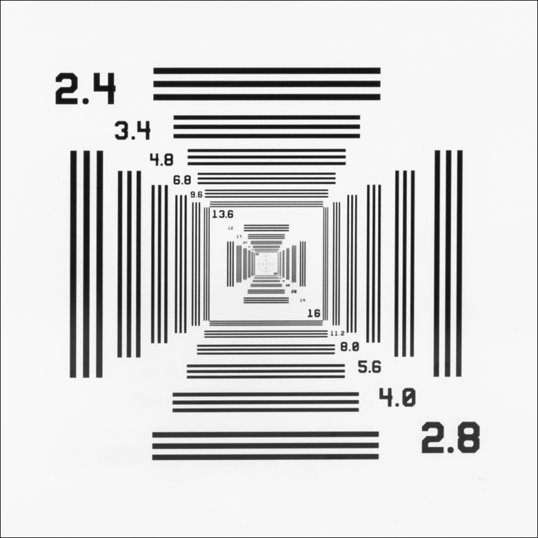
| Optical Specifications | |
|---|---|
| Pattern | LRa Chrome |
| Background | Clear |
| Surface Flatness | ≤15 µm |
| Chrome Optical Densityb | ≥3.0 |
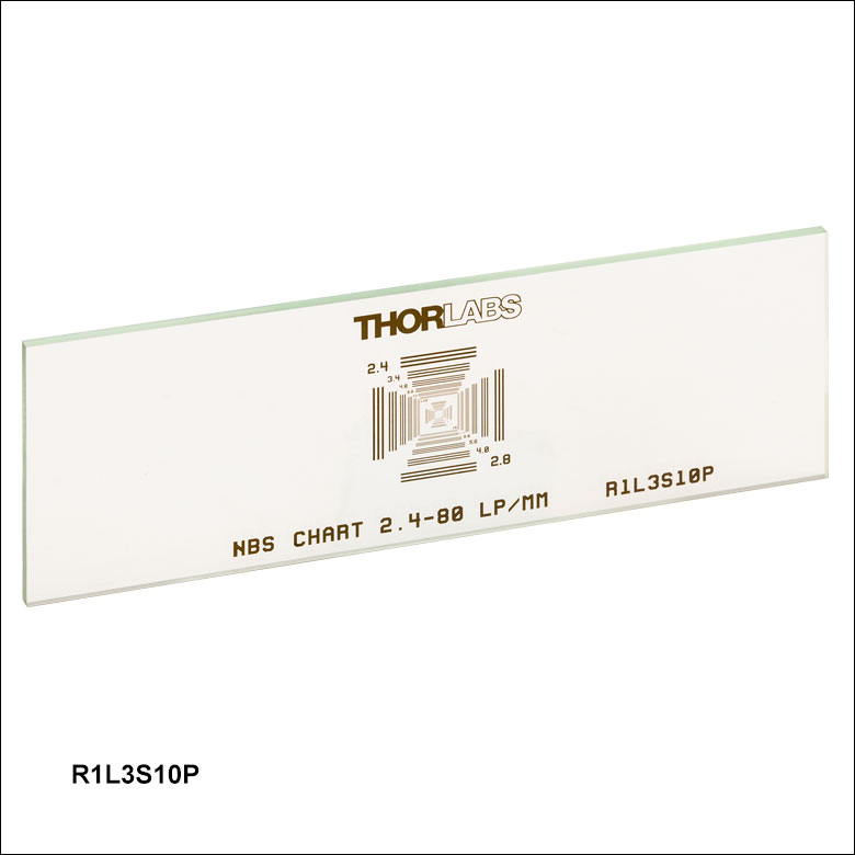
- 3英寸x1英寸(76.2 mm x 25.4 mm)测试靶,单通扫描测量分辨率
- 中心具有十字线的NBS 1952测试靶
- 分辨率从2.4到80 lp/mm
- 三条线一个集合降低伪分辨率
Thorlabs的3英寸x1英寸(76.2 mm x 25.4 mm) NBS 1952分辨率测试靶提供48组线,分24种不同频率,范围从2.4到80线对(一条亮线和一条暗线)每毫米,如表G7.2所示。NBS 1952测试靶中心具有长宽同为610 µm的十字线以及直径为250 µm和500 µm的两个同心圆。测试靶的线集排布使得能够至沿一个方向扫描图案(水平或垂直)就能查看每种分辨率,所以单通就能确定光学系统的分辨率。关于NBS 1952图样请看上方的分辨率测试靶标签。
由于这些测试靶以三条线为一个集合,因此能够降低伪分辨率的发生概率,防止不准确的分辨率测量结果。关于伪分辨率的更多信息,请看分辨率测试靶标签。
此测试靶通过在0.06英寸(1.5 mm)厚的钠钙玻璃基底上镀低反射、真空溅射铬制成,在430 nm处具有≥3的光学密度。暗图案和透明基底适合前照和一般应用。
| Table G7.2 NBS 1952 Pattern Resolutions | ||||||||||||||||||||||||
|---|---|---|---|---|---|---|---|---|---|---|---|---|---|---|---|---|---|---|---|---|---|---|---|---|
| Resolution (lp/mm) | 2.4 | 2.8 | 3.4 | 4.0 | 4.8 | 5.6 | 6.8 | 8.0 | 9.6 | 11.2 | 12 | 13.6 | 14 | 16 | 17 | 20 | 24 | 28 | 34 | 40 | 48 | 56 | 68 | 80 |
| Line Width (µm) | 208.3 | 176.8 | 147.1 | 125.0 | 104.2 | 89.3 | 73.5 | 62.5 | 52.1 | 44.6 | 41.7 | 36.8 | 35.7 | 31.3 | 29.4 | 25.0 | 20.8 | 17.9 | 14.7 | 12.5 | 10.4 | 8.9 | 7.4 | 6.3 |

 放大
放大| Optical Specifications | |
|---|---|
| Pattern | LRa Chrome |
| Background | Clear |
| Surface Flatness | ≤15 µm |
| Chrome Optical Densityb | ≥3.0 |
- 3英寸x3英寸(76.2 mm x 76.2 mm)测试靶,单通扫描测量分辨率
- 中心具有十字线的NBS 1952测试靶
- 分辨率从0.48到16 lp/mm
- 三条线一个集合降低伪分辨率
Thorlabs的3英寸x3英寸(76.2 mm x 76.2 mm) NBS 1952分辨率测试靶提供48组线,分24种不同频率,范围从0.48到16线对(一条亮线和一条暗线)每毫米,如表G8.2所示。NBS 1952测试靶中心具有长宽同为3100 µm的十字线以及直径为1250 µm和2500 µm的两个同心圆。测试靶的线集排布使得能够至沿一个方向扫描图案(水平或垂直)就能查看每种分辨率,所以单通就能确定光学系统的分辨率。关于NBS 1952图样请看上方的分辨率测试靶标签。
由于这些测试靶以三条线为一个集合,因此能够降低伪分辨率的发生概率,防止不准确的分辨率测量结果。关于伪分辨率的更多信息,请看分辨率测试靶标签。
此测试靶通过在0.06英寸(1.5 mm)厚的钠钙玻璃基底上镀低反射、真空溅射铬制成,在430 nm处具有≥3的光学密度。暗图案和透明基底适合前照和一般应用。
| Table G8.2 NBS 1952 Pattern Resolutions | ||||||||||||||||||||||||
|---|---|---|---|---|---|---|---|---|---|---|---|---|---|---|---|---|---|---|---|---|---|---|---|---|
| Resolution (lp/mm) | 0.48 | 0.56 | 0.68 | 0.8 | 0.96 | 1.12 | 1.36 | 1.6 | 1.92 | 2.24 | 2.4 | 2.72 | 2.8 | 3.2 | 3.4 | 4.0 | 4.8 | 5.6 | 6.8 | 8.0 | 9.6 | 11.2 | 13.6 | 16 |
| Line Width (µm) | 1041.7 | 892.9 | 735.3 | 625 | 520.8 | 446.4 | 367.6 | 312.5 | 260.4 | 223.2 | 208.3 | 183.8 | 176.8 | 156.3 | 147.1 | 125.0 | 104.2 | 89.3 | 73.5 | 62.5 | 52.1 | 44.6 | 36.8 | 31.3 |

 放大
放大
|
| Optical Specifications | ||
|---|---|---|
| Item # | R2L2S1P | R2L2S1N |
| Pattern | LRa Chrome | Clear |
| Background | Clear | LRa Chrome |
| Surface Flatness | ≤15 µm | |
| Chrome Optical Densityb | ≥3.0 | |
- 频率从1到18 cycles/mm (见表G9.1)
- 确定光学系统的分辨率
- 2英寸x2英寸(50.8 mm x 50.8 mm)钠钙玻璃基板
- 提供正靶和负靶
Thorlabs的2英寸x2英寸(50.8 mm x 50.8 mm) NBS 1963A分辨率测试靶提供26组线,频率从1到18 cycles/mm,对应的周期大小从1.0 mm到55.6 µm(详见右表和分辨率测试靶标签)。图案中的每组线包含五条水平线和五条垂直线,标有以cycles/mm表示的线频率,如图G9.2所示。根据系统能够分辨的最高频率的线组确定光学系统的分辨率。
这些分辨率靶具有正、负两种版本。R2L2S1P正测试靶在透明基底上镀低反射铬图案,适合前照和普通应用。R2L2S1N负测试靶在基底上镀相同的低反射铬膜,使图案部分透明,适合背照和高亮照明应用。

 放大
放大
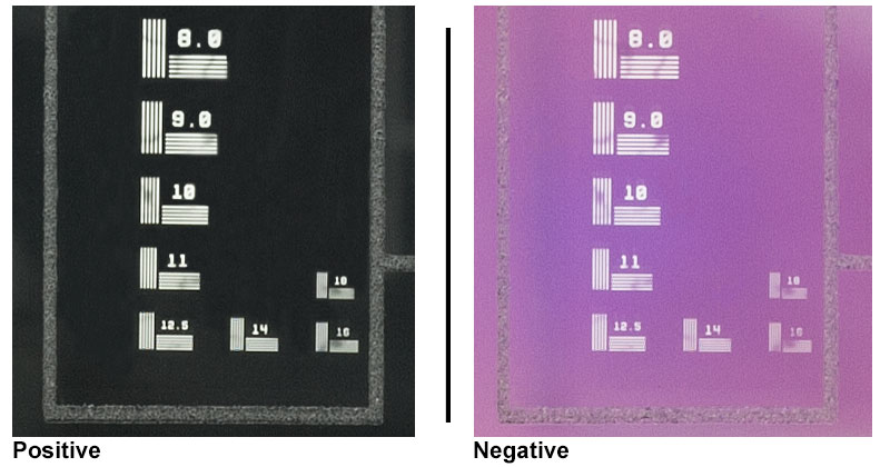
Click for Details
图G10.2 R2L2S1N1负靶上频率为32和29 cycles/mm的线组。放大图片将展示从7.1到228 cycles/mm的所有线组。

Click for Details
图G10.1 R2L2S1P1正靶上频率为32和29 cycles/mm的线组。放大图片将展示从7.1到228 cycles/mm的所有线组。
| Optical Specifications | ||
|---|---|---|
| Item # | R2L2S1P1 | R2L2S1N1 |
| Pattern | LRa Chrome | Clear |
| Background | Clear | LRa Chrome |
| Surface Flatness | ≤15 µm | |
| Chrome Optical Densityb | ≥3.0 | |
- 频率从1到228 cycles/mm (表G10.3)
- 确定光学系统的分辨率
- 2英寸x2英寸(50.8 mm x 50.8 mm)钠钙玻璃基板
- 提供正靶和负靶
Thorlabs的2英寸x2英寸(50.8 mm x 50.8 mm) NBS 1963A高频分辨率测试靶提供48组线,频率从1到228 cycles/mm,对应的周期大小从1.0 mm到4.4 µm(详见表G10.3和分辨率测试靶标签)。图案中的每组线包含五条水平线和五条垂直线,标有以cycles/mm表示的线频率,如图G10.1和G10.2所示。根据系统能够分辨的最高频率的线组确定光学系统的分辨率。
这些分辨率靶具有正、负两种版本。R2L2S1P1正测试靶在透明基底上镀低反射铬图案,适合前照和普通应用。R2L2S1N1负测试靶在基底上镀相同的低反射铬膜,使图案部分透明,适合背照和高亮照明应用。
• |

 放大
放大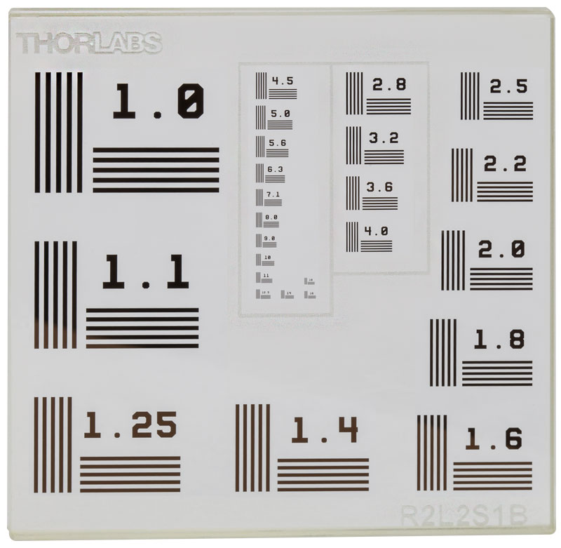
| Optical Specifications | |
|---|---|
| Design | Liquid Crystal Polymer Between N-BK7 Substrate and N-BK7 Protective Glass |
| Substrate Thickness | 2.0 mm (0.08") |
| Protective Glass Thickness | 0.2 mm |
- 确定偏振光学系统的分辨率
- 具有正负图案的双折射测试靶
- 频率从1到18 cycles/mm (见表G11.3)
- 2英寸×2英寸(50.8 mm × 50.8 mm) N-BK7玻璃基底
Thorlabs提供2英寸×2英寸(50.8 mm × 50.8 mm)双折射NBS 1963A分辨率测试靶,将双折射图样夹在两块N-BK7玻璃基底中间制成。测试图样只有通过一对正交偏振片才能看到(图G11.1所示)。
通过调节正交偏振片相对测试靶的方向,测试靶可以显示正负两种图样。如果正交偏振片与玻璃四边对齐则成正像。如果正交偏振片与玻璃四边为45°夹角则成负像。因为对偏振灵敏,这种分辨率测试靶非常适合校准和测试双折射成像系统和显微镜、偏振显微镜、Nomarski模式显微镜、偏振成像系统或穆勒矩阵偏振测量仪的分辨率。
这种测试靶共有26组线,每组5条横线和5条竖线。每组线标有数字,表示以cycles/mm为单位的数值。最大频率18 cycles/mm,最小周期仅为0.0556 mm。详见上面的分辨率测试靶标签。图案只有通过一对正交偏振片才能看到,靶上刻有两个矩形提供参考。图G11.2展示图案相对所刻矩形的位置。
|

 放大
放大- 1英寸x1英寸(25.4 mm x 25.4 mm)正扇形星靶
- 确定光学系统的分辨率
- 在钠钙玻璃上镀低反射、真空溅射铬
Thorlabs供应四种带扇形星(西门子星)图案的1英寸(25.4 mm)方形测试靶。两款为正测试靶(R1L1S2P和R1L1S3P),另两个为负测试靶(R1L1S2N和R1L1S3N)
R1L1S2P和R1L1S2N靶在360°内有36个扇形,R1L1S3P和R1L1S3N靶在360°内有72个扇形。每个图案内径为Ø200 µm,外径为10 mm。36个扇形靶的分辨率是1.2 lp/mm至57.3 lp/mm,72个扇形靶的分辨率是2.3 lp/mm至114.6 lp/mm。通过观察光学系统能分辨的相邻扇形条接近图案中心的程度来确定光学系统的分辨率。扇形星图案细节请见分辨率测试靶标签。
| Item # | Pattern | Background | Surface Flatness | Chrome Optical Density | Pattern Outer Diameter | Center Circle Diameter | Number of Bars | Resolution at Outer Diameter | Resolution at Center Circle |
|---|---|---|---|---|---|---|---|---|---|
| R1L1S2P | Low-Reflectivity Chrome | Clear | ≤15 µm | ≥3.0 at 430 nm | 10 mm | 200 µm | 36 Over 360° | 1.2 lp/mm | 57.3 lp/mm |
| R1L1S2N | Clear | Low-Reflectivity Chrome | |||||||
| R1L1S3P | Low-Reflectivity Chrome | Clear | 72 Over 360° | 2.3 lp/mm | 114.6 lp/mm | ||||
| R1L1S3N | Clear | Low-Reflectivity Chrome |

 放大
放大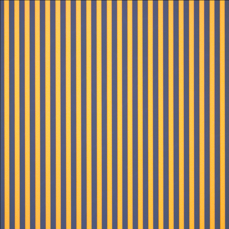
| Optical Specifications | |
|---|---|
| Pattern | Alternating Clear and LRa Chrome Lines |
| Border | LR Chrome |
| Surface Flatness | ≤15 µm |
| Chrome Optical Densityb | ≥3.0 |
- 3英寸x1英寸(76.2 mm x 25.4 mm)方波朗奇刻线测试靶
- 图案线对:0.5 lp/mm到500 lp/mm
- 65 mm x 17 mm大通光孔径
- 确定光学系统的分辨率、视场畸变和齐焦稳定性
- 在钠钙玻璃上沉积低反射率真空溅射铬图案
- 通过MLS203P2载玻片支架兼容我们的MLS203显微镜位移台
Thorlabs提供分辨率范围从0.5线对(一条明线和一条暗线)每毫米(lp/mm)到500 lp/mm的朗奇刻线测试靶。这些方波、恒定间距的横条和空间图案的制备方法是在3.00英寸 x 1.00英寸 x 0.06英寸(76.2 mm x 25.4 mm x 1.5 mm)钠钙玻璃基底上沉积有深色低反射铬图案。这样能留出65 mm x 17 mm大通光孔径,在背照和高亮度照明应用中提供优异性能。玻璃基底的尺寸和标准显微镜载玻片相同。这些朗奇刻线测试靶可用于评估光学系统的分辨率、视场畸变和齐焦稳定性。

 放大
放大| Optical Specifications | ||
|---|---|---|
| Item # | R1L3S6P | R1L3S6PR |
| Pattern | LRa Chrome | LRa Chrome |
| Background | Clear | Chrome |
| Surface Flatness | ≤15 µm | ≤15 µm |
| Chrome Optical Densityb | ≥3.0 | - |
| Chrome Reflectanceb | - | LRa Chrome: < 10% Chrome: >40% |
- 3英寸x1英寸(76.2 mm x 25.4 mm)可变线栅测试靶
- 分辨率从1.25到250 lp/mm
- 确定光学系统的分辨率
- 在钠钙玻璃上真空溅射低反射铬膜
- 通过MLS203P2载玻片支架兼容我们的MLS203显微镜位移台
- 可选高对比度反射式正测试靶
Thorlabs提供两种3英寸 x 1英寸可变光栅正靶,具有18组线栅,分辨率从每毫米1.25线对(一条亮线和一条暗线)( lp/mm)到250 lp/mm。表G14.2列出了每种可用的分辨率。通过确定系统能够分辨的最高分辨率线栅测量光学系统分辨率。
R1L3S6P正测试靶在透明钠钙玻璃上镀低反射铬图案,适合前照和普通应用。R1L3S6PR反射式正测试靶在镀铬背景上镀深色低反射铬膜图案,图案和背景之间的高对比度适用于反射应用。详情请查看曲线图标签。
|

 放大
放大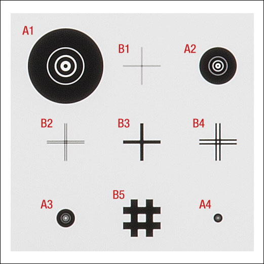
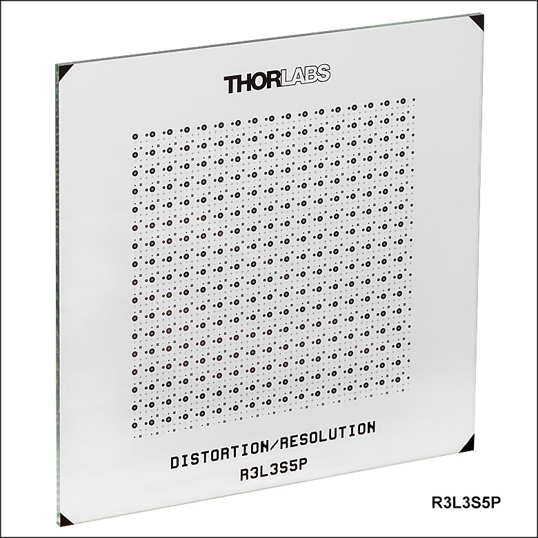
Click to Enlarge
图483B:R3L3S5P靶上较小网格的近视图,图中加了标记(见表483D和483BE)
Click to Enlarge
图483A:R3L3S5P靶近视图
| Table 483C Optical Specifications | |
|---|---|
| Pattern | LRa Chrome |
| Background | Clear |
| Surface Flatness | ≤15 µm |
| Chrome Optical Densityb | ≥3.0 |
- 以网格排列的同心圆和十字线图样
- 四种不同尺寸的同心圆图样和五种不同尺寸的十字线图样
- 测量成像系统的分辨率、畸变和放大率
- 3英寸x3英寸(76.2 mm x 76.2 mm)钠钙玻璃基板
Thorlabs的3英寸x3英寸(76.2 mm x 76.2 mm)同心圆和十字线网格靶提供289个独立网格,以17行和17列排在一个2英寸x2英寸大格子中。每个网格具有不同尺寸的四个同心圆图样和五个十字线图样。在图483B中,网格中的同心圆和十字线都加了标记,靶本身没有标记。每个同心圆图样具有七种不同半径,每个十字线图样具有一个或两个十字。这些图样的尺寸细节请看下表。
此测试靶通过在0.06英寸(1.5 mm)厚的钠钙玻璃基底上镀低反射、真空溅射铬制成,在430 nm处具有≥3的光学密度。暗图案和透明基底适合前照和一般应用。
| Table 483D Concentric Circles | |||||||
|---|---|---|---|---|---|---|---|
| Circle Patterna | R1 | R2 | R3 | R4 | R5 | R6 | R7 |
| A1 | 31.3 µm | 62.5 µm | 125 µm | 140.6 µm | 234.4 µm | 242.2 µm | 500 µm |
| A2 | 15.6 µm | 31.3 µm | 62.5 µm | 70.3 µm | 117.2 µm | 121.1 µm | 250 µm |
| A3 | 7.8 µm | 15.6 µm | 31.3 µm | 35.2 µm | 58.6 µm | 60.5 µm | 125 µm |
| A4 | 3.9 µm | 7.8 µm | 15.6 µm | 17.6 µm | 29.3 µm | 30.3 µm | 62.5 µm |
| Table 483E Crosshairs | |||
|---|---|---|---|
| Crosshair Patterna | Single or Double Line | Length/Width | Line Widthb |
| B1 | Double | 500 µm | 6.25 µm |
| B2 | Double | 500 µm | 12.5 µm |
| B3 | Single | 500 µm | 50 µm |
| B4 | Double | 500 µm | 25 µm |
| B5 | Double | 500 µm | 100 µm |

 放大
放大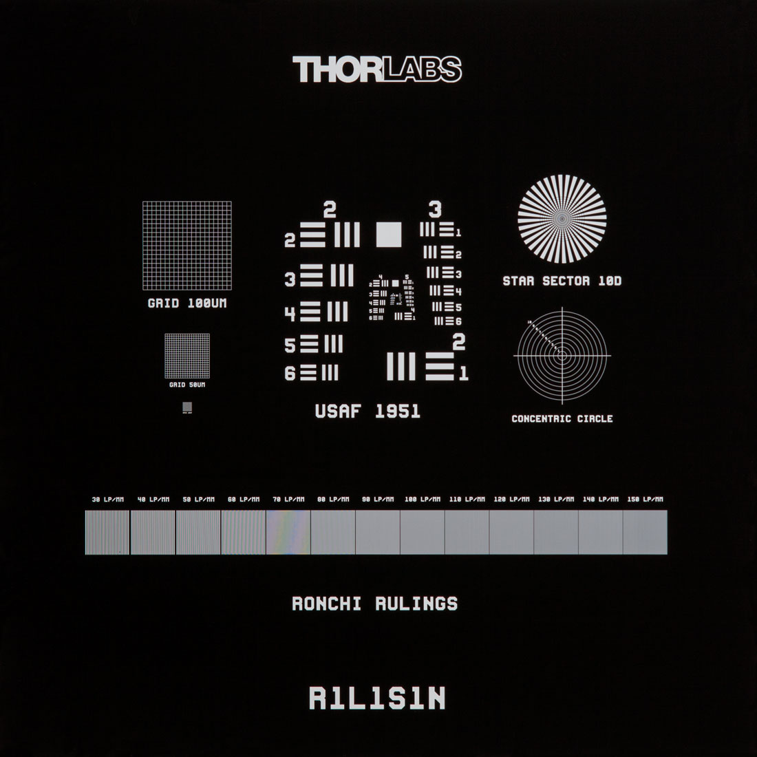
Click to Enlarge
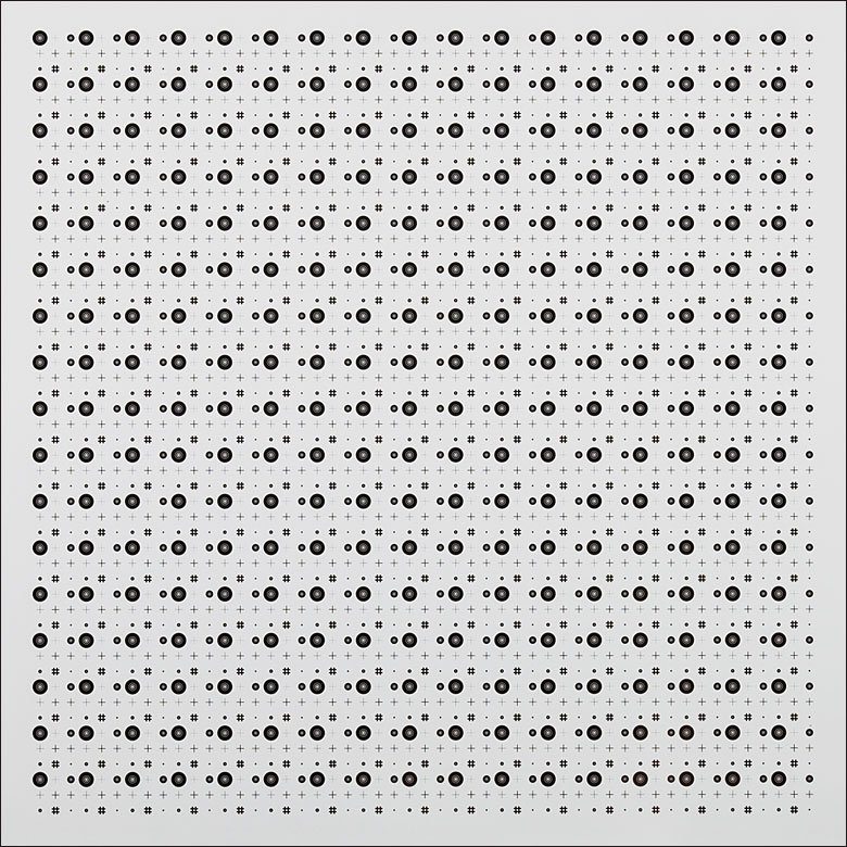
图G16.1 R1S1L1N负靶的显微镜图像
| Optical Specifications | ||
|---|---|---|
| Item # | R1L1S1P | R1L1S1N |
| Pattern | LRa Chrome | Clear |
| Background | Clear | LRa Chrome |
| Surface Flatness | ≤15 µm | |
| Chrome Optical Densityb | ≥3.0 | |
- 测量图像畸变,像散和其它像差
- 边长18 mm(0.71英寸),厚1.5毫米方形靶
- 确定光学系统的分辨率
- 包括1951 USAF图样、扇形星状、同心圆、网格和朗奇(Ronchi)刻度
- 可选正图样和负图样
Thorlabs提供18 mm × 18 mm × 1.5 mm正负分辨率/畸变组合测试靶,通过在钠钙玻璃基底上镀低反射、真空溅射铬制成,在430 nm处具有≥3的光学密度。它们是校准成像系统和显微镜位移台的理想选择。
测试靶包括一个1951 USAF图案(2到7组)、一个扇形星图案、同心圆图案、网格图案(100 µm、50 µm和10 µm)以及朗奇刻线图案(30到150 lp/mm)。这些测试靶适合测量分辨率、场曲、聚焦误差和像散。USAF 1951测试靶适合测量成像分辨率。详见上面的分辨率测试靶标签。网格图案适合测量图像畸变,同心圆适合识别成像系统中的聚焦误差、像散和其它像差。朗奇刻线适合评估分辨率、场曲和齐焦稳定性。
这些分辨率靶具有正、负两种版本。R1L1S1P正测试靶在透明基底上镀低反射铬图案,适合前照和普通应用。R1L1S1N负测试靶在基底上镀相同的低反射铬膜,使图案部分透明,适合背照和高亮照明应用。
| Target Feature | Details | Target Feature | Details |
|---|---|---|---|
| 1951 USAF Target | Groups 2 - 7 | Concentric Circles | 10 Circles with Radii from 100 µm to 1000 µm in 100 µm Intervals, Labeled 1 to 10 |
| Grids | 20 x 20 Arrays with 100 µm, 50 µm, and 10 µm Pitch | Ronchi Rulings | 13 Rulings from 30 lp/mma to 150 lp/mm in 10 lp/mm Intervals |
| Star Sector | 36 Bars through 360°, Ø10 µm Radius Center Circle, and Ten Concentric Circles with Radii from 50 µm to 500 µm in 50 µm Intervals | ||

 放大
放大
|

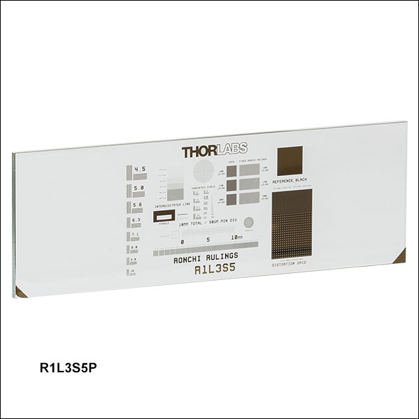
Click to Enlarge
图444A:R1L3S5P特写图
| Optical Specifications | |
|---|---|
| Pattern | LRa Chrome |
| Background | Clear |
| Surface Flatness | ≤15 µm |
| Chrome Optical Densityb | ≥3.0 |
- 3英寸x1英寸(76.2 mm x 25.4 mm)测试靶
- 包括NBS 1963A图案、扇形星、同心圆、网格、朗奇刻线等(见表444B)
- 确定光学系统的分辨率
- 测量图像畸变、像散和其它像差
- 通过MLS203P2载波片支架兼容我们的MLS203显微镜位移台
Thorlabs提供3英寸x1英寸x0.06英寸(76.2 mm x 25.4 mm x 1.5 mm)正分辨率/畸变组合测试靶,通过镀低反射、真空溅射铬制成,在430 nm处具有≥3的光学密度。它们是校准成像系统和显微镜位移台的理想选择。它们的尺寸适合装入我们的MLS203P2载波片支架,以此和MLS203显微镜位移台一起使用。
此测试靶包括一个NBS 1963A图案、一个扇形星(西门子星)图案、同心圆图案、网格图案、朗奇刻线以及其它图案(见表444B)。这些测试靶适合测量分辨率、场曲、聚焦误差和像散。NBS 1963A、扇形星和同心圆非常适于测量成像分辨率。详见上面的分辨率测试靶标签。网格图案适合测量成像系统引起的畸变。朗奇刻线适合评估分辨率、场曲和齐焦稳定性。
| Table 444B Specifications | |||
|---|---|---|---|
| Target Feature | Details | Target Feature | Details |
| NBS 1963A | Frequencies from 4.5 cycles/mm to 228 cycles/mm (See List Above) | Concentric Circles | 10 Circles with Radii from 100 µm to 1000 µm in 100 µm Intervals |
| Distortion Grid (Squares) | 3 Grids: 100 lp/mma, 150 lp/mm, 200 lp/mm | Fixed Ronchi Rulings | 3 Rulings:100 lp/mm, 150 lp/mm, and 200 lp/mm |
| Distortion Grid (Dots) | 3 Grids: 400 µm Pitch of Ø80 µm Dots, 200 µm Pitch of Ø 40 µm Dots, 100 µm Pitch of Ø20 µm Dots | Variable Ronchi Rulings | 20 Rulings (Each 1 mm x 1 mm): 10 lp/mm to 200 lp/mm in 10 lp/mm Intervals |
| Two-Point Resolution Dots | Ø25 µm, Ø20 µm, Ø15 µm, Ø12.5 µm, Ø10 µm, Ø7.5 µm, and Ø5 µm | Pinholes | Ø25 µm, Ø20 µm, Ø15 µm, Ø12.5 µm, Ø10 µm, Ø7.5 µm, and Ø5 µm |
| Interdigitated Lines | 6.25 lp/mm, 12.5 lp/mm, 25 lp/mm, 50 lp/mm, 100 lp/mm, and 200 lp/mm | Micrometers | 3 Rulers: 10 mm Scale with 50 µm Divs, 1 mm Scale with 10 µm Divs, and 1mm x 1 mm XY Scale with 50 µm Divs |
| Sector Star | 36 Bars through 360°, 50 µm Radius Center Circle, and Ten Concentric Circles with Radii from 100 µm to 500 µm in 50 µm Intervals | ||