 Products Home
Compact Housings for Custom Devices
- Aluminum Enclosures for Custom Electronics or Fiber Modules
- Round or Rectangular Housings for Custom In-Line Devices
- End Plates Available with Electrical Connectors or Fiber Bulkheads
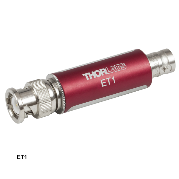
ET1
Empty In-Line BNC Feedthrough Housing
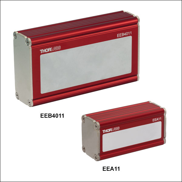
EEB3311
Customizable Electronics Housing, Blank End Plates
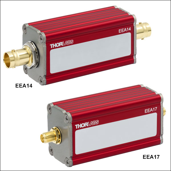
EEA14
Customizable Electronics Housing, BNC Connectors
EEBFPF2
End Plate with
Dual FC/PC Fiber Bulkheads
EECEPBNC
End Plate with BNC Connector
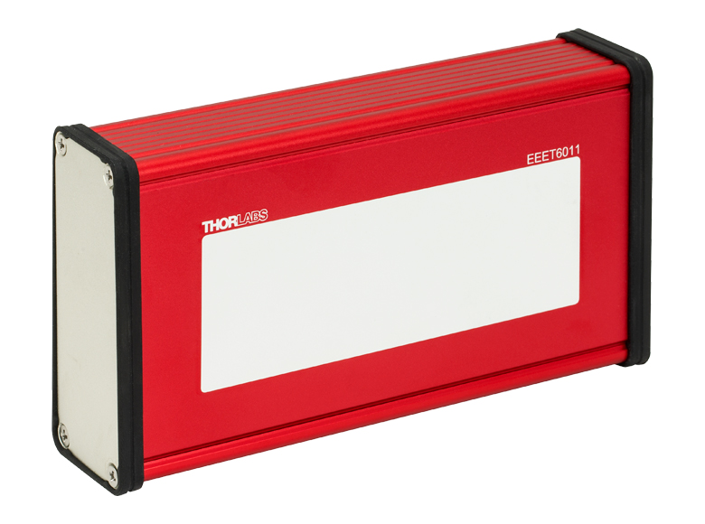
EEET6011
Customizable Electronics Housing,
Removable Side Panel


Please Wait
| Quick Links |
|---|
| BNC Feedthrough Housing |
| Extruded Aluminum Housings |
| Housings with Blank End Plates |
| Housings with Electrical Connectors |
| End Plates |
| Fiber Bulkheads |
| Electrical Connectors |
| Blank End Plates |
| Rubber Bezels |
| Clamps |
| Aluminum Side Clamps |
| Plastic Double-Sided Clamps |
| Screws |
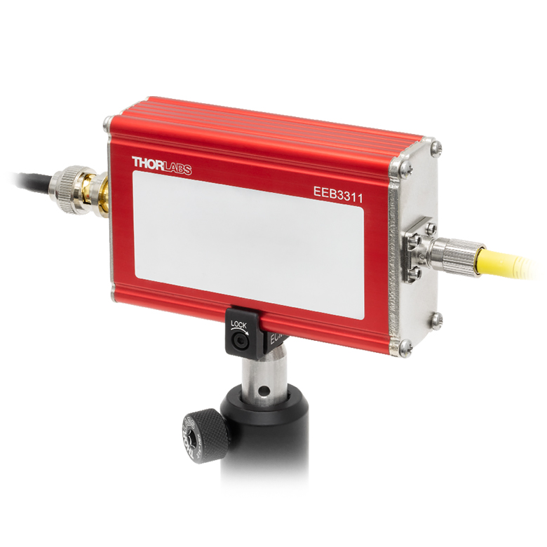
Click to Enlarge EEB3311 Housing with BNC Cable and FC/PC Fiber Patch Cable Attached
Features
- Compact, Customizable, Aluminum Device Housings
- In-Line BNC Feedthrough Housing
- Extruded Housings with Blank End Plates or Electrical Connectors
- Extruded Housings Available with Removable Side Panels
- End Plates Available with Fiber Bulkheads, Electrical Connectors, or No Connectors
- Facilitate Quick Integration of Custom Electronics or Fiber Components
- Blank Area Engraved on Housing for Write-On Labels
- Rubber Bezels for Extruded Housings
- Aluminum and Plastic Side Clamps for Mounting or Stacking Housings
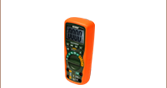
These compact housings are empty enclosures that enable the user to create custom electrical circuits, such as filters, voltage dividers, or impedance matchers, as well as fiber modules, such as fused couplers or fiber detectors.
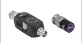
BNC Feedthrough Housing
The ET1 tube housing has a male BNC connector on one side and a female BNC connector on the other side. This in-line feedthrough housing is ideal for simple circuits made from a small number of standard electronic components or more complex circuits built with surface-mounted elements on a small printed circuit board (PCB).
Click to Enlarge
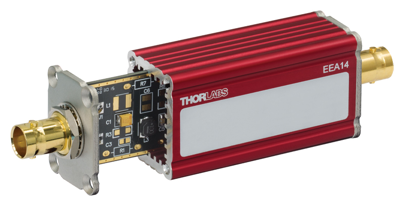
The slotted body of the EEA14 housing is shown here with the EEAPCB1 Customizable PCB (shown with electrical elements, not included) partially inserted into it.
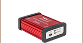
Extruded Aluminum Housings
For modules that require more space, extruded aluminum housings in several sizes up to 1.75" x 2.25" x 4.00" are available. These housings are slotted inside to accept printed circuit boards and are offered with blank end plates, female BNC connectors, or female SMA connectors. Housings are also available with a removable side plate. For detailed dimensions of the housings, please click on either the red Docs icons ( ) or the blue icons (
![]() ) below.
) below.
Extra end plates and screws are available for many of the housings sold below. We offer blank end plates and end plates with female BNC or female SMA connectors for all sizes of extruded aluminum housings below, as well as end plates with FC/PC, FC/APC, or SMA fiber bulkheads for the EEB 1.00" x 2.25" housings.
Thorlabs also offers streak-free black silicone rubber bezels to provide protection from scratches and surfaces with higher friction than the extrusion's exterior. All bezels are secured by fitting them between the end plate and the extrusion. Aluminum side clamps are available to mount the housings. The clamps have a #8 (M4) counterbore, which allows them to be mounted to a Ø1/2" post or other surface with an 8-32 (M4) tap. Alternatively, double-sided plastic clamps are available to mount a housing on top of another housing for a secure, compact setup.
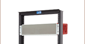
In addition to the BNC feedthrough and extruded aluminum housings below, enclosures for larger electronics systems are also available. Options include customizable benchtop enclosures, a flanged benchtop enclosure designed for easy assembly, and 19" rack enclosures for electronics for use with 19" equipment racks.
| Posted Comments: | |
user
(posted 2023-07-20 16:33:41.547) It would be great to have box with two input/ output bnc per plate cdolbashian
(posted 2023-07-20 05:01:12.0) Thank you for your feedback! I have submitted this request internally as a potential future stock offering. user
(posted 2019-07-20 17:57:03.09) Why is it so expensive? I'd like to buy a number of these but at $48 it doesn't make sense to do so. Let me know if there's a cheaper option. Right now there are filters with these enclosures that cost $4 more than what you're charging.
Thanks,
Nick YLohia
(posted 2019-07-23 02:41:15.0) Hello, the cost of manufacturing is the reason for the price (especially given that that output connector is a specialty item). The filters being referred to that utilize this ET1 housing are sold for $69.86/pc (as of 7/23) as opposed to the sale price of $48.33/pc for just the housing (ET1). Unfortunately, we do not offer alternative solutions for this at the moment. melanie
(posted 2018-09-18 10:58:01.907) Can you please confirm that the housings are electrically isolated from the outer conductor on the BNC output and input ? I'm concerned about pick-up from eg power supplies.
This question applies to all the filters Thorlabs are marketing, as well as the custom housing.
I'm failrly confident your answer is "YES", but I just want to confirm. Thank you. YLohia
(posted 2018-09-24 09:08:33.0) Hello, thank you for contacting Thorlabs. The BNC case is directly and electrically connected to the body housing. ludoangot
(posted 2016-12-27 17:36:04.707) The recent introduction of your side clamps for your housings prompts me to suggest a housing accepting a standard arduino uno board and some side clamps which could fit your 30mm and 60mm cage system. Arduino is likely used by some of your customers alongside Thorlabs opto-mechanical elements (I am one of them), and a dedicated housing with cage clamps would be much welcome. tfrisch
(posted 2016-12-27 02:57:02.0) Hello, thank you for contacting Thorlabs. I have posted this feedback in our internal engineering forum. |

 Zoom
Zoom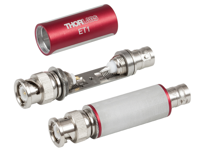
Click to Enlarge
The ET1 housing is shown here with its outer shell removed (top). A blank label is included on the back side (bottom).
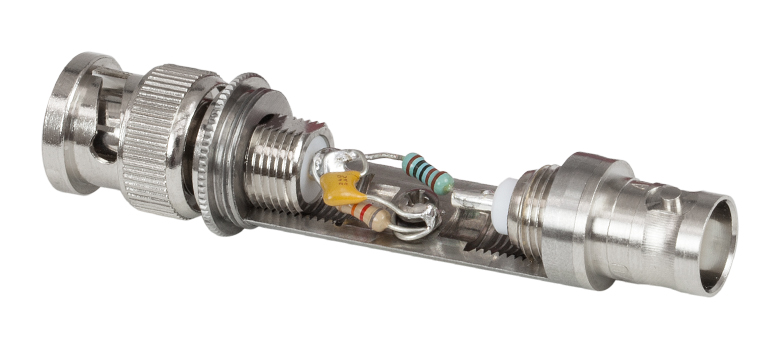
Click to Enlarge
ET1 Housing with an RC Circuit Made from Standard Electronic Elements (Not Included)
- Ø0.63" × 2.61" In-Line BNC Feedthrough Housing
- Compatible with Off-the-Shelf Electronic Elements
- Accepts 10 mm x 15 mm PCB
- Male and Female BNC Connectors
- Blank Area to Label Custom Circuits
The ET1 tube housing is an in-line (feedthrough) BNC structure with a male BNC connector on one side and a female BNC connector on the other side (as shown in the image to the right). The 2-56 screw in the base provides a convenient connection to ground, and the compact design can easily house a small number of standard electronic elements (e.g., resistors, capacitors, etc.). The image to the right shows the ET1 with a simple RC filter using standard circuit elements.
The ET1 electronic housing can hold a small (10 mm × 15 mm) form factor PCB that, using surface mounted elements, allows for the inclusion of many electronic elements. For example, Thorlabs' low- and high-pass filters (which were the basis for the ET1) house 5th and 6th order elliptical filters composed of anywhere from 8 to 15 electronic elements. The back side of the enclosure includes a blank label for identifying custom circuits. For detailed dimensions, click on the Docs icon ( ) below.

 Zoom
Zoom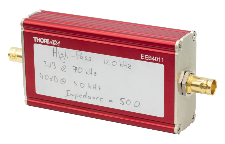
Click to Enlarge
Each housing has a blank area for writing labels to identify custom devices.
Click to Enlarge
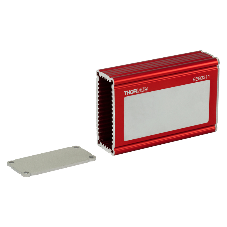
EEB3311 Housing with End Plate Removed
Click to Enlarge
Extrusion Interior Dimensions
- Seven Sizes Available
- Four Interior Sides are Slotted for Use with Printed Circuit Boards (PCBs)
- Each Housing Includes Blank End Plates
- Blank Area to Label Custom Devices
- Extra End Plates Available Below
These extruded housings are empty enclosures with nickel-plated ends. For detailed dimensions of each enclosure, click on the blue icon (![]() ) in the table below. The front side of each enclosure includes a blank label area for identification. Note that these housings are made from extruded bar stock, and as such, some minor cosmetic defects in the finished products are to be expected.
) in the table below. The front side of each enclosure includes a blank label area for identification. Note that these housings are made from extruded bar stock, and as such, some minor cosmetic defects in the finished products are to be expected.
Each housing has two blank end plates which can be machined to accommodate custom connectors. We recommend using a step drill bit to machine a hole in the end plate; a standard, single-size drill bit may cause deformation in the plate. The easily removable end plates are held in place with No 4. flat-head countersunk screws that pass through the Ø0.125" countersunk through holes at each corner.
Extra end plates are available below. Blank end plates, end plates with BNC or SMA electrical connectors, and end plates with FC/PC, FC/APC, or SMA fiber bulkheads can be purchased. Extra No. 4 screws (Item # TF44038), compatible with all housings, are also available below. Fiber end plates require M3 screws (Item # M3BHTF25), which are also available below.
| Item # | Housing Sizea |
Interior Dimensionsb | Accessories (Sold Separately) | |||||||
|---|---|---|---|---|---|---|---|---|---|---|
| L1 | L2 | L3 | Slot Width |
Slot Depth |
PCB Item # |
End Plate Typesc | Bezel Item # |
Side Clamps | ||
| EEA11 | 2.38" (60.5 mm) |
0.77" (19.6 mm) |
1.02" (25.9 mm) |
0.070" ± 0.005" (1.8 mm ± 0.1 mm) |
0.045" (1.1 mm) |
EEAPB1 EEAPCB1 |
Blank (Two Included), BNC or SMA Electrical Connectors |
EEARB | Aluminum for 1" or 1.25" Side, Double Sided, Plastic for 1.25" Side |
|
| EEB3311 | 3.33" (84.6 mm) |
0.77" (19.6 mm) |
2.02" (51.3 mm) |
0.070" ± 0.005" (1.8 mm ± 0.1 mm) |
0.045" (1.1 mm) |
EEB33PCB1 | Blank (Two Included), FC/PC, FC/APC or SMA Fiber Bulkheads, BNC or SMA Electrical Connectors |
EEBRB | Aluminum for 1" or 2.25" Side, Double Sided, Plastic for 2.25" Side |
|
| EEB4011 | 4.00" (101.6 mm) |
0.77" (19.6 mm) |
2.02" (51.3 mm) |
0.070" ± 0.005" (1.8 mm ± 0.1 mm) |
0.045" (1.1 mm) |
EEB40PCB1 | ||||
| EEC3011 | 3.00" (76.2 mm) |
1.02" (25.9 mm) |
1.52 (38.6 mm) |
0.070" ± 0.005" (1.8 mm ± 0.1 mm) |
0.045" (1.1 mm) |
- | Blank (Two Included), BNC or SMA Electrical Connectors |
EECRB | Aluminum for 1.25" or 1.75" Side, Double Sided, Plastic for 1.25" or 1.75" Side |
|
| EEC4011 | 4.00" (101.6 mm) |
1.02" (25.9 mm) |
1.52 (38.6 mm) |
0.070" ± 0.005" (1.8 mm ± 0.1 mm) |
0.045" (1.1 mm) |
- | ||||
| EED3011 | 3.00" (76.2 mm) |
1.52" (38.6 mm) |
2.02" (51.3 mm) |
0.070" ± 0.005" (1.8 mm ± 0.1 mm) |
0.045" (1.1 mm) |
- | Blank (Two Included), BNC or SMA Electrical Connectors |
EEDRB | Aluminum for 1.75" or 2.25" Side, Double Sided, Plastic for 1.75" or 2.25" Side |
|
| EED4011 | 4.00" (101.6 mm) |
1.52" (38.6 mm) |
2.02" (51.3 mm) |
0.070" ± 0.005" (1.8 mm ± 0.1 mm) |
0.045" (1.1 mm) |
- | ||||
- Click on the blue icon (
 ) to view a mechanical drawing.
 - For L1, L2, and L3 definitions, see the drawing to the top left.
- Screws to attach the end plates to the extrusions are available below in packages of 25. End plates with fiber bulkheads require the use of M3BHTF25 M3 pan head screws; all other end plates require the use of TF44038 No. 4 countersunk flat head screws.

 Zoom
Zoom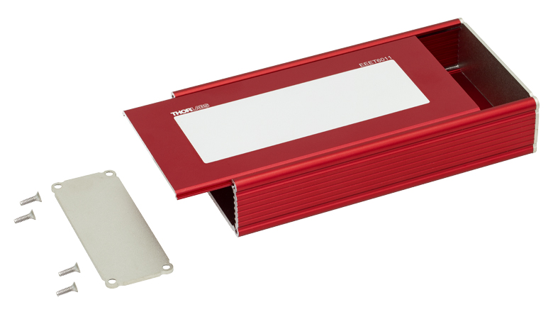
Click to Enlarge
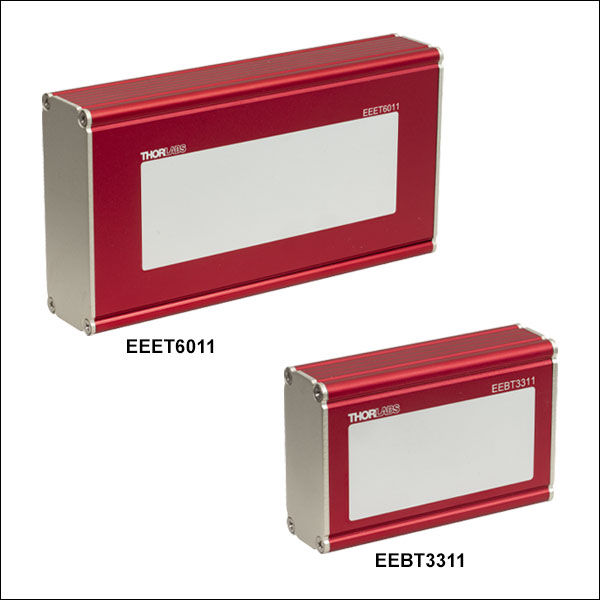
Each housing has a removeable side panel.
Click to Enlarge
Extrusion Interior Dimensions
- Five Sizes Available
- Two Interior Sides are Slotted for Use with Printed Circuit Boards (PCBs)
- Removable Side Panel
- Each Housing Includes Blank End Plates
- Blank Area to Label Custom Devices
- Extra End Plates Available Below
These extruded housings are empty enclosures with nickel-plated ends. For detailed dimensions of each enclosure, click on the blue icon (![]() ) in the table below. The front side of each enclosure includes a blank label area for identification. Note that these housings are made from extruded bar stock, and as such, some minor cosmetic defects in the finished products are to be expected.
) in the table below. The front side of each enclosure includes a blank label area for identification. Note that these housings are made from extruded bar stock, and as such, some minor cosmetic defects in the finished products are to be expected.
Each housing has two blank end plates which can be machined to accommodate custom connectors. We recommend using a step drill bit to machine a hole in the end plate; a standard, single-size drill bit may cause deformation in the plate. The easily removable end plates are held in place with
Each of these housings also includes a removable side panel that allows for easy access to a PCB placed inside. The removable side panel and the panel opposite do not contain slots; a PCB placed within one of these housings needs to be placed parallel in relation to the removable panel. In order to remove the side panel, the four screws securing the end plate must be removed, along with the end plate itself. Once the end plate is removed, the side panel should easily slide out (see the image to the right).
Extra end plates are available below. Blank end plates, end plates with BNC or SMA electrical connectors, and end plates with FC/PC, FC/APC, or SMA fiber bulkheads can be purchased. Extra No. 4 screws (Item # TF44038), compatible with all housings, are also available below. Fiber end plates require M3 screws (Item # M3BHTF25), which are also available below.
| Item # | Housing Sizea |
Interior Dimensionsb | Accessories (Sold Separately) | |||||||
|---|---|---|---|---|---|---|---|---|---|---|
| L1 | L2 | L3 | Slot Width |
Slot Depth |
PCB Item # |
End Plate Typesc | Bezel Item # |
Side Clamps | ||
| EEBT3311 | 3.33" (84.6 mm) |
0.80" (20.3 mm) |
2.02" (51.3 mm) |
0.070" ± 0.005" (1.8 mm ± 0.1 mm) |
0.045" (1.1 mm) |
EEB33PCB1 | Blank (Two Included), FC/PC, FC/APC, or SMA Fiber Bulkheads, BNC or SMA Electrical Connectors |
EEBRB | Aluminum for 1" or 2.25" Side, Double Sided, Plastic for 2.25" Side |
|
| EEBT4011 | 4.00" (101.6 mm) |
0.80" (20.3 mm) |
2.02" (51.3 mm) |
0.070" ± 0.005" (1.8 mm ± 0.1 mm) |
0.045" (1.1 mm) |
EEB40PCB1 | ||||
| EECT3011 | 3.00" (76.2 mm) |
1.05" (26.6 mm) |
1.52" (38.6 mm) |
0.070" ± 0.005" (1.8 mm ± 0.1 mm) |
0.045" (1.1 mm) |
- | Blank (Two Included), BNC or SMA Electrical Connectors |
EECRB | Aluminum for 1.25" or 1.75" Side, Double Sided, Plastic for 1.25" or 1.75" Side |
|
| EEDT4011 | 4.00" (101.6 mm) |
1.55" (39.3 mm) |
2.02" (51.3 mm) |
0.070" ± 0.005" (1.8 mm ± 0.1 mm) |
0.045" (1.1 mm) |
- | Blank (Two Included), BNC or SMA Electrical Connectors |
EEDRB | Aluminum for 1.75" or 2.25" Side, Double Sided, Plastic for 1.75" or 2.25" Side |
|
| EEET6011 | 6.00" (152.4 mm) |
1.05" (26.6 mm) |
3.02" (76.7 mm) |
0.070" ± 0.005" (1.8 mm ± 0.1 mm) |
0.045" (1.1 mm) |
- | Blank (Two Included) | EEERB | Aluminum for 1.25" or 3.25" Side, Double Sided, Plastic for 1.25" Side |
|
- Click on the blue icon () to view a mechanical drawing.
- For L1, L2, and L3 definitions, see the drawing to the top right.
- Screws to attach the end plates to the extrusions are available below in packages of 25. End plates with fiber bulkheads require the use of M3BHTF25 M3 pan head screws; all other end plates require the use of TF44038 No. 4 countersunk flat head screws (eight included with each housing).

 Zoom
ZoomClick to Enlarge
The slotted body of the EEA14 housing is shown here with the EEAPCB1 Customizable PCB (shown with electrical elements, not included) partially inserted into it.
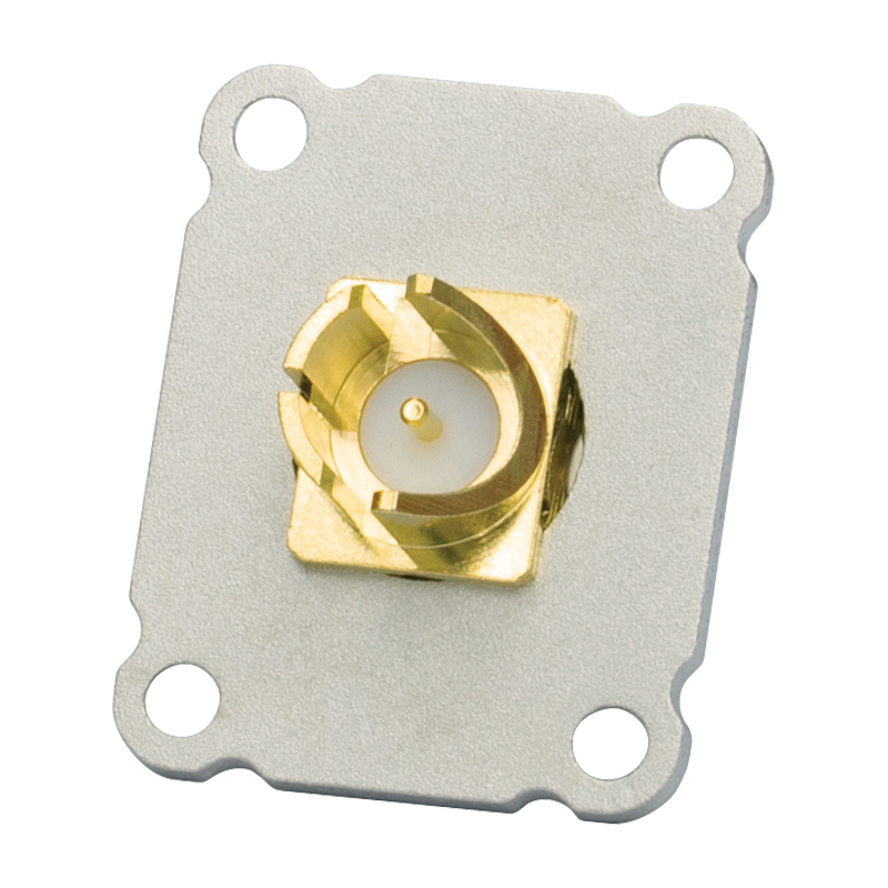
Click to Enlarge
Back View of the EEA14's Slotted Female BNC Connector
Click to Enlarge
Extrusion Interior Dimensions
- 1.00" x 1.25" x 2.51" Extruded Housings
- Slotted Construction for a 0.99" x 2.30" or 0.75" x 2.30" PCB
- Two Connector Types:
- EEA14: Two Female BNC Connectors
- EEA17: Two Female SMA Connectors
- Blank Area to Label Custom Circuits
These Extruded Electronics Housings are empty 1.00" x 1.25" x 2.51" enclosures with nickel-plated ends. The EEA14 has two female BNC connectors and the EEA17 has two female SMA connectors. For detailed dimensions of each enclosure, click on the blue icon (![]() ) in the table. These enclosures are ideal for housing a wide variety of electronic devices that can be built with surface-mounted elements, such as Thorlabs' EEAPCB1 Customizable Printed Circuit Board (shown in the image to the right), which gives users the ability to create their own RCL circuits.
) in the table. These enclosures are ideal for housing a wide variety of electronic devices that can be built with surface-mounted elements, such as Thorlabs' EEAPCB1 Customizable Printed Circuit Board (shown in the image to the right), which gives users the ability to create their own RCL circuits.
The end plates of these housings are easily removable and are held in place with No. 4 flat-head countersunk Phillips screws. The front side of each enclosure includes a blank label for identifying custom circuits. Note that these housings are made from extruded bar stock, and as such, some minor cosmetic defects in the finished products are to be expected.
| Item # | Connectors | Housing Sizea |
Internal Dimensionsb | Accessories (Sold Separately) | ||||||
|---|---|---|---|---|---|---|---|---|---|---|
| L1 | L2 | L3 | Slot Width |
Slot Depth |
Printed Circuit Boards | Bezel Item # |
Side Clamps | |||
| EEA14 | Two BNC Femalec | 2.38" (60.5 mm) |
0.77" (19.6 mm) |
1.02" (25.9 mm) |
0.070" ± 0.005" (1.8 mm ± 0.1 mm) |
0.045" (1.1 mm) |
EEAPB1 EEAPCB1 |
EEARB | Aluminum for 1" or 1.25" Side, Double Sided, Plastic for 1.25" Side |
|
| EEA17 | Two SMA Female | |||||||||
- Click on the blue icon () to view a mechanical drawing.
- For L1, L2, and L3 definitions, see the drawing to the top left.
- These connectors feature a 75 Ω impedance. If mated to a 50 Ω BNC connector, they will introduce an impedance mismatch that may degrade performance.

 Zoom
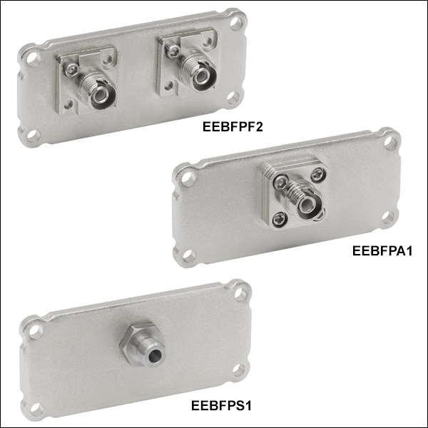
Zoom| Item # | Connector Style | End Plate Dimensions | Compatible Housing |
|---|---|---|---|
| EEBFPF1 | FC/PC Fiber Bulkhead | 1.00" x 2.25" | EEB3311 EEBT3311 EEB4011 EEBT4011 |
| EEBFPF2 | 2 FC/PC Fiber Bulkheads | ||
| EEBFPA1 | FC/APC Fiber Bulkhead | ||
| EEBFPA2 | 2 FC/APC Fiber Bulkheads | ||
| EEBFPS1 | SMA Fiber Bulkhead | ||
| EEBFPS2 | 2 SMA Fiber Bulkheads |
- End Plates with FC/PC, FC/APC, or SMA Bulkheads Available
- Available with One or Two Bulkheads
- Offset Connectors for Compatibility with Internal Components
Extra end plates with 2.2 mm wide-key FC/PC, 2.0 mm narrow-key FC/APC, or SMA905 fiber bulkheads are available for many of the housings sold above. See the table to the right for compatible housings.
These end plates are shipped pre-assembled and are available with either one or two bulkheads. The FC/PC and FC/APC versions have an insertion loss* of <0.5 dB when measured at 635 nm with FC-terminated SM600 fibers. The SMA end plate has a typical insertion loss of <1.5 dB when used with a pair of Ø200 µm core multimode fibers. The connectors for these end plates are offset above center to accommodate a PCB or mounted fiber coupler installed in the housing.
Four screws are included with each end plate for mounting to a compatible housing. Extra M3 Phillips pan head screws are available below in packs of 25. These screws are compatible with all of the housings sold above except the ET1.
*Please Note: When PM fiber is used, the insertion loss will increase to >1.0 dB. The insertion loss for the FC/PC mating sleeve is only valid when using a FC/PC connector while the FC/APC mating sleeve will maintain the stated insertion loss with any FC connector.

 Zoom
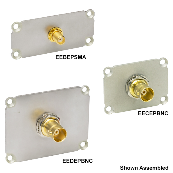
Zoom| Item # | Connector Style |
End Plate Dimensions |
Compatible Housing |
|---|---|---|---|
| EEAEPBNC | Female BNCa | 1.00" x 1.25" | EEA11 EEA14 EEA17 |
| EEAEPSMA | Female SMA | ||
| EEBEPBNC | Female BNCa | 1.00" x 2.25" | EEB3311 EEB4011 EEBT3311 EEBT4011 |
| EEBEPSMA | Female SMA | ||
| EECEPBNC | Female BNCa | 1.25" x 1.75" | EEC3011 EEC4011 EECT3011 |
| EECEPSMA | Female SMA | ||
| EEDEPBNC | Female BNCa | 1.75" x 2.25" | EED3011 EED4011 EEDT4011 |
| EEDEPSMA | Female SMA |
- Four Sizes Available (See Table for Housing Compatibility)
- BNC or SMA Electrical Connectors
- Accept TF44038 No. 4 Countersunk Screws (Available Below)
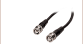
Extra end plates with BNC or SMA connectors are available for many of the housings sold above. See the table to the right for compatible housings.
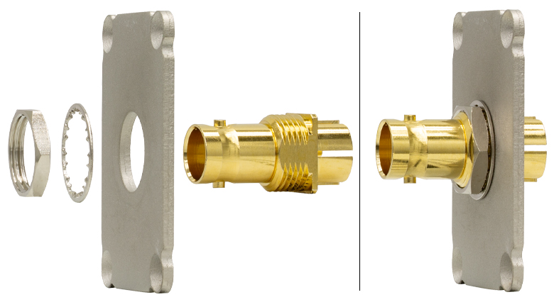
Click to Enlarge
Assembly of EEBEPBNC End Plate
Each endplate contains four countersunk Ø0.125" (Ø3.2 mm) through holes. They also have a pre-drilled hole for their respective connector type. The components require some assembly when shipped, as shown in the photo to the right. Both the BNC and SMA connectors included with these items are female connectors. For electrical specifications of the connectors, click on the red Docs icon (![]() ) next to the item # below.
) next to the item # below.
No. 4 Phillips flat-head countersunk screws are available below in packs of 25. These screws are compatible with all of the housings sold above except the ET1.

 Zoom
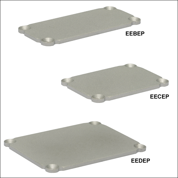
Zoom| Item # | End Plate Dimensions | Compatible Housings |
|---|---|---|
| EEAEP | 1.00" x 1.25" | EEA11 EEA14 EEA17 |
| EEBEP | 1.00" x 2.25" | EEB3311 EEB4011 EEBT3311 EEBT4011 |
| EECEP | 1.25" x 1.75" | EEC3011 EEC4011 EECT3011 |
| EEEEP | 1.25" x 3.25" | EEET6011 |
| EEDEP | 1.75" x 2.25" | EED3011 EED4011 EEDT4011 |
- Use to Cap or Make Custom End Plates
- 0.08" (2.0 mm) Thick End Plates
- Accept TF44038 No. 4 Countersunk Screws (Available Below)
- Five Sizes Provide Compatibility for Six of Our Housings
Extra blank end plates are available for many of the housings sold above. See the table to the right for compatible housings.
We recommend using a step drill bit to machine a hole in the end plate; a standard, single-size drill bit may cause deformation in the plate.
Each end plate contains four countersunk Ø0.125" (Ø3.2 mm) through holes. No. 4 Phillips flat-head countersunk screws are available below in packs of 25. These screws are compatible with all of the housings sold above except the ET1.

 Zoom
Zoom
Click to Enlarge
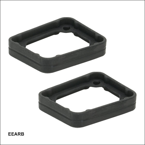
Bezel Dimensions
These rubber bezels attach to the rectangular electronics housings sold above. Once secured to the appropriate housing, they protect the extrusion and end plates from general wear on the sides and provide surfaces with higher friction than the extrusion's exterior. Each bezel has a lip that is sandwiched between the end plate and extrusion edge; the four screws used to attached the end plate to the extrusion pass through holes in the lip to secure the bezel in place. Compared to a bezel that would simply slip over the end plate's exterior, this design leaves more usable space across the end plate surface and prevents the bezels from being accidentally removed from the extrusions.
These bezels are sold in pairs and are available in five sizes; see the table below for compatibility.
| Bezel Item # | Exterior Dimensionsa | Cutout Dimensionsa | Compatible Housings |
|---|---|---|---|
| EEARB | 1.35" x 1.10" x 0.26" (34.29 mm x 27.94 mm x 6.60 mm) |
1.06" x 0.81" x 0.02" (26.92 mm x 20.57 mm x 0.51 mm) |
EEA11 EEA14 EEA17 |
| EEBRB | 2.35" x 1.10" x 0.26" (59.69 mm x 27.94 mm x 6.60 mm) |
2.06" x 0.81" x 0.02" (52.32 x 20.57 mm x 0.51 mm) |
EEB3311 EEB4011 EEBT3311 EEBT4011 |
| EECRB | 1.85" x 1.35" x 0.26" (46.99 mm x 34.29 mm x 6.60 mm) |
1.56" x 1.06" x 0.02" (39.62 mm x 26.92 mm x 0.51 mm) |
EEC3011 EEC4011 EECT3011 |
| EEDRB | 2.35" x 1.85" x 0.26" (59.69 mm x 46.99 mm x 6.60 mm) |
2.06" x 1.56" x 0.02" (52.32 mm x 39.62 mm x 0.51 mm) |
EED3011 EED4011 EEDT4011 |
| EEERB | 3.35" x 1.35" x 0.26" (85.09 mm x 34.29 mm x 6.60 mm) |
3.06" x 1.06" x 0.02" (77.72 mm x 26.92 mm x 0.51 mm) |
EEET6011 |

 Zoom
Zoom
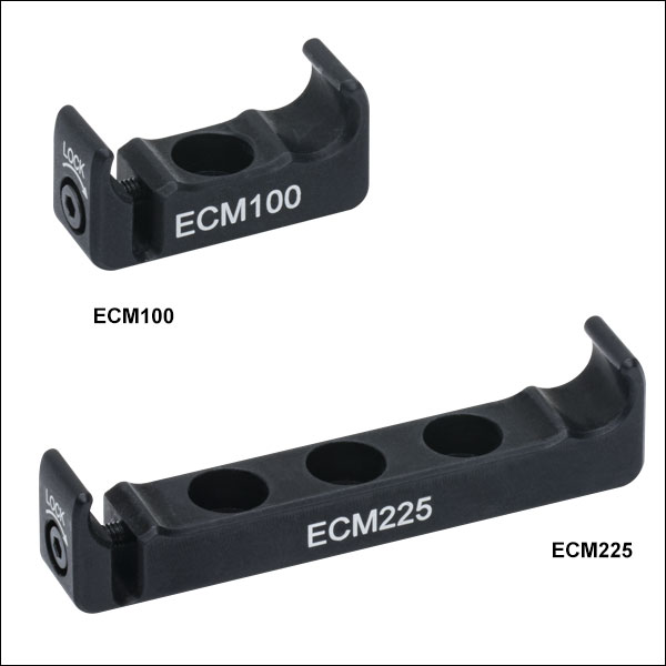
These anodized aluminum clamps provide secure mounting for the rectangular electronics housings sold above. Five sizes of clamps are available, and each is designed to fit on one side of the housing; see the table below for compatibility. The clamp can snap onto the side of the appropriate housing and the flexure lock can be tightened using the 2 mm (5/64") hex locking screw on the side.
Each clamp has at least one #8 (M4) counterbore on the bottom; the ECM225 has three and the ECM325 has five counterbores. The counterbores allow the clamps to be mounted on a Ø1/2" post or any surface with an 8-32 (M4) tap. The clamp must be mounted via the counterbore before the electronics housing is attached, as the counterbore will not be accessible once the housing is secured in the clamp.
| Clamp Item # | ECM100 | ECM125 | ECM175 | ECM225 | ECM325 |
|---|---|---|---|---|---|
| Width | 1.00" | 1.25" | 1.75" | 2.25" | 3.25" |
| Compatible Housings |
EEA11 EEA14 EEA17 EEB3311 EEB4011 EEBT3311 EEDT4011 |
EEA11 EEA14 EEA17 EEC3011 EEC4011 EECT3011 EEET6011 |
EEC3011 EEC4011 EED3011 EED4011 EECT3011 EEDT4011 |
EEB3311 EEB4011 EED3011 EED4011 EEBT3311 EEBT4011 EEDT4011 |
EEET6011 |
| Mounting Holes |
One #8 (M4) Counterbore | Three #8 (M4) Counterbores | Five #8 (M4) Counterbores | ||

 Zoom
Zoom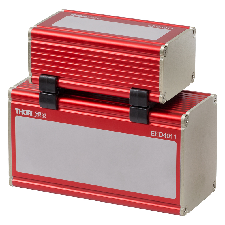
Click to Enlarge
EEC3011 Mounted on EED4011 using Two EPS175 Double-Sided Clamps
These ABS plastic clamps provide secure mounting for the rectangular electronics housings sold above. Three sizes of clamps are available, and each is designed to attach two housings with a common side width; see the table below for compatibility. The clamp easily snaps onto the side of the appropriate housing. To remove the clamp, slide it along the edge of the housing until it comes off at the corner.
These clamps are sold in pairs.
| Clamp Item # | EPS125 | EPS175 | EPS225 |
|---|---|---|---|
| Width | 1.25" | 1.75" | 2.25" |
| Compatible Housings |
EEA11 EEA14 EEA17 EEC3011 EEC4011 EECT3011 EEET6011 |
EEC3011 EEC4011 EED3011 EED4011 EECT3011 EEDT4011 |
EEB3311 EEB4011 EED3011 EED4011 EEBT3311 EEBT4011 EEDT4011 |

 Zoom
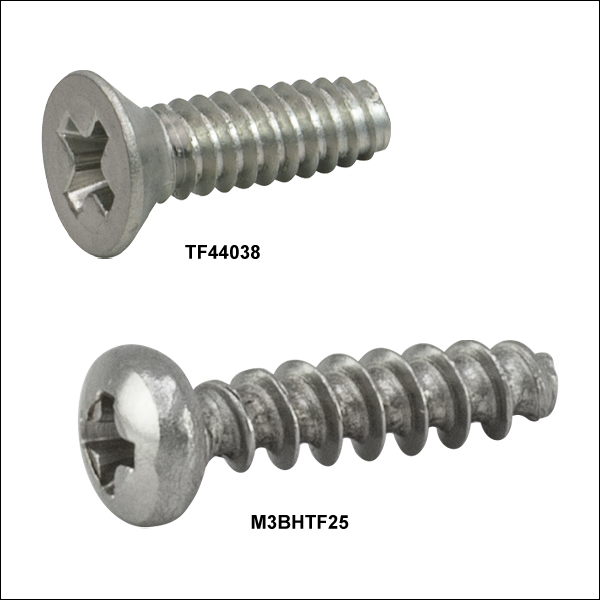
Zoom- Thread-Forming #1 Phillips Head Screws:
- No. 4 Thread with Countersunk Flat Head (Item # TF44038)
- M3 Thread with Pan Head (Item # M3BHTF25)
- Used to Secure Compatible End Plates to Extruded Aluminum Housings
- Available in Packs of 25
Extra thread-forming, #1 drive Phillips head screws are available in packs of 25 and are compatible with all of the housings sold above except the ET1. They are used to secure a compatible end plate to a housing using the four corner holes. Screws that are 3/8" long have No. 4 threads and countersunk flat heads that can be used with end plates with a countersunk hole in each corner (all end plates sold above except those with fiber connectors). Screws with 12 mm long M3 threads have pan heads for use with end plates that have a through hole in each corner (the end plates with fiber connectors sold above).