 Products Home
Polaris® Kinematic Collimators
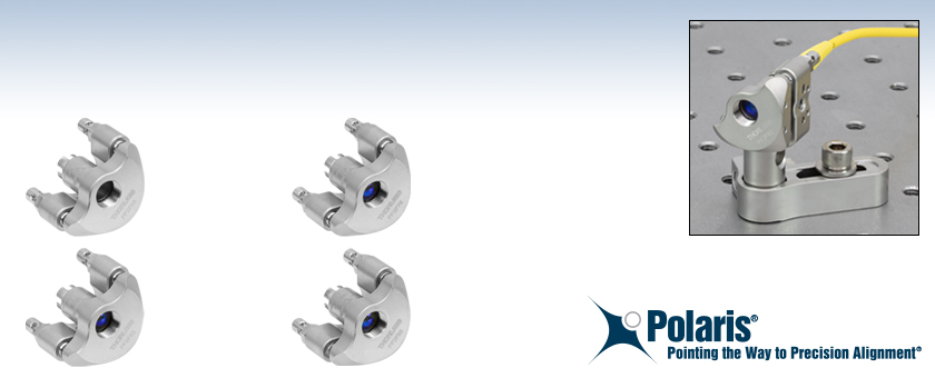
- Kinematic, Fixed Focus Collimators for FC/PC-Terminated Fiber
- Pre-Aligned for 532, 633, 780, or 850 nm Wavelengths
- Pitch and Yaw Adjustment Range of ±5°
- Minimal Temperature-Dependent Hysteresis
PF2F53
Kinematic, Fixed Focus Collimator, 532 nm
PF2F78
Kinematic, Fixed Focus Collimator, 780 nm
PF2F63
Kinematic, Fixed Focus Collimator, 633 nm
PF2F85
Kinematic, Fixed Focus Collimator, 850 nm
Application Idea
The PF2F63 kinematic collimator is used to collimate the output of a P1-S405-FC-1 fiber patch cable.


Please Wait
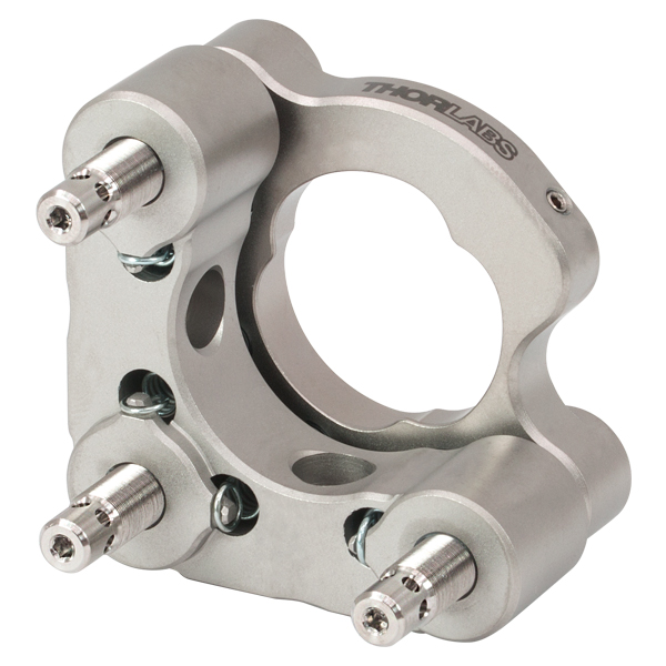
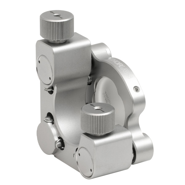
Click to Enlarge
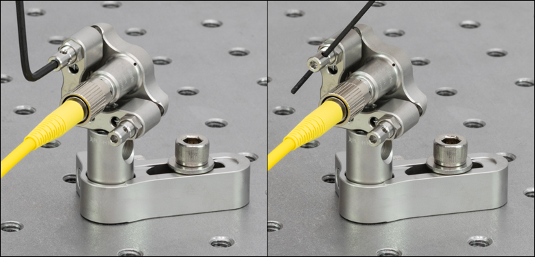
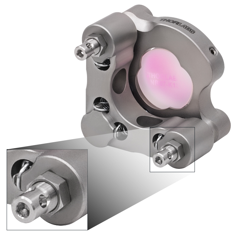
Figure 1.1 There are two methods for adjusting the angle of our Polaris® kinematic collimators: using a 5/64" (2.0 mm) hex key in the end of the adjuster, or using the same or smaller hex key through the Ø0.07" (Ø1.8 mm) adjuster side holes
| Quick Links | |
|---|---|
| Kinematic Collimators | |
| Lock Nut | |
| Locking Collar & Spanner Wrench | |
| 5/64" Hex Key Adjusters | |
| Torque Wrenches |
Features
- Machined from Heat-Treated Stainless Steel with Low Coefficient of Thermal Expansion (CTE)
- Pre-Aligned Fiber Collimators with FC/PC Connectors (Three 2.2 mm Wide Key Slots) for Single Mode Patch Cables
- Collimators Aligned for 532, 633, 780, or 850 nm Wavelengths
- Hardened Stainless Steel Ball Contacts with Sapphire Seats for Durability and Smooth Movement
- 8-32 (M4 x 0.7) Threaded Mounting Hole for Post Mounting
- Matched Actuator/Body Pairs Provide Smooth Kinematic Adjustment
- Testing Guarantees ≤2 μrad Deviation after 16 °C Temperature Cycle (See the Test Data Tab for Details)
- Passivated Stainless Steel Surface Ideal for Vacuum and High-Power Laser Cavity Applications
- Custom Mount Configurations and Alignment Wavelengths Available by Contacting Tech Sales
Polaris® Kinematic, Fixed Focus Collimators combine the high-quality beam output of our fixed focus collimation packages with the remarkable mechanical properties of our Polaris® mounts, making them the ultimate solution for fiber collimation applications requiring stringent long-term alignment stability. These fiber collimation packages are pre-aligned to collimate light from an FC/PC-terminated fiber with diffraction-limited performance. Due to chromatic aberration, the effective focal length (EFL) of the aspheric lens is wavelength dependent. The alignment wavelength indicates the wavelength of ideal beam divergence (see the Graphs and Calculations tabs for more information).
The aspheric lens is factory aligned for collimation at the alignment wavelength when connected to its specified single mode fiber patch cable. In addition, the aspheric lens has an AR coating on both sides that minimizes surface reflections (see the Graphs tab). For some applications they may also be used at other wavelengths within the AR coating range; please refer to the theoretical divergence plot for each collimator to determine if it is appropriate for your application. The operating temperature range for these collimators is -30 °C to 200 °C.
These fiber collimators are optimized for use with single mode fiber patch cables. For improved performance, we recommend using these collimators with our AR-coated single mode fiber optic patch cables. These cables feature an antireflective coating on one fiber end for increased transmission and improved return loss at the fiber-to-free-space interface. Please note performance specifications are guaranteed only when used with single mode fiber.
Design
Machined from heat-treated stainless steel, Polaris mounts utilize precision-matched adjusters with ball contacts and sapphire seats to provide smooth kinematic adjustment. As shown in the Test Data tab, these mounts have undergone extensive testing to ensure high-quality performance. The Polaris design addresses all of the common causes of beam misalignment; please refer to the Design Features tab for detailed information.
Post Mounting
The design of the kinematic elements on these mounts prevents the user having to put their hand in front of the collimator when doing a kinematic adjustment or having to uninstall the collimator to mount this onto a post. Unlike the traditional counterbore on our Polaris mounts, this design comes with two 8-32 (M4 x 0.7) threaded holes for mounting on a post; one 8-32 (M4 x 0.7) cap screw is included with each collimator. They also feature Ø2 mm alignment pin holes around each mounting hole, allowing for precision alignment when paired with our counterbored Ø1/2" or Ø1" Posts for Polaris Mounts. They can also be mounted on threaded posts, however caution should be used when using anything other than the included cap screw to ensure that the screw being used does not make contact with the collimator itself.
Cleanroom and Vacuum Compatibility
All Polaris collimators sold on this page are designed to be compatible with cleanroom and vacuum applications. See the Design Features tab for more information.
Alternatives
We offer another line of adjustable collimation packages called FiberPorts that are well suited for a wide range of wavelengths. These are ideal solutions for adjustable, compact fiber couplers. For other collimation and coupling options, please see our Collimator Guide tab or contact Tech Sales.
| Item #a | PF2F53(/M) | PF2F63(/M) | PF2F78(/M) | PF2F85(/M) |
|---|---|---|---|---|
| Collimator Specifications | ||||
| Alignment Wavelengtha | 532 nm | 633 nm | 780 nm | 850 nm |
| Lens AR Coating | Ravg < 0.5%, 350 - 700 nm | Ravg < 0.5%b, 650 - 1050 nm | Ravg < 0.5%, 650 - 1050 nm | |
| Output Beam Diameterc | 2.1 mm | 2.41 mm | ||
| Full-Angle Beam Divergenced | 0.02° | 0.022° | 0.026° | 0.03° |
| Numerical Aperture | 0.25 | 0.26 | 0.25 | |
| Focal Length Calculated at Alignment Wavelength | 10.90 mm | 10.99 mm | 11.07 mm | 11.12 mm |
| Connector Type | FC/PC, Three 2.2 mm Wide Key Slots | |||
| Mount Specifications | ||||
| Adjuster Drive | 5/64" (2.0 mm) Hex, Ø0.07" (Ø1.8 mm) Side Adjustment Holes | |||
| Adjuster Pitch | 3/16"-130 Matched Actuator/Body Pairs | |||
| Measured Point-to-Point Mechanical Resolution per Adjuster |
5 µrad (Typical) 2 µrad (Achievable) |
|||
| Resolutione | ~11 mrad/rev | |||
| Mechanical Angular Range (Nominal) | ±5° | |||
| Beam Deviationf After Thermal Cycling | <2.0 μrad | |||
| Mounting | Two 8-32 (M4 x 0.7) Threaded Holes at 90° | |||
| Alignment Pin Holes | Two Ø2 mm Holes for DIN 7-m6 Ground Dowel Pin at Each Mounting Hole | |||
| Vacuum Compatibilityg | 10-9 Torr at 25 °C with Proper Bake Out; 10-5 Torr at 25 °C without Bake Out DuPont Krytox® LVP High-Vacuum Grease Vapor Pressure: 10-13 Torr at 20 °C ,10-5 Torr at 200 °C EPO-TEK® 353ND (353NDPK) Epoxy Meets Low Outgassing Standards NASA ASTM E595, Telcordia GR-1221 |
|||
| Operating Temperature Range | -30 to 200 °C | |||
| Table 3.1 Coating Information | ||
|---|---|---|
| Coating Designation | A | B |
| Applicable Item #s | PF2F53(/M) | PF2F63(/M), PF2F78(/M), PF2F85(/M) |
| Coating Range | 350 - 700 nm | 650 - 1050 nm |
| Reflectance | Ravg < 0.5% within Coating Range | Ravg < 0.5% within Coating Range |
Click to Enlarge
Click Here for Raw Data
Figure 3.3 The blue shaded region indicates the specified 350 - 700 nm wavelength range for optimum performance.
Click to Enlarge
Click Here for Raw Data
Figure 3.2 The blue shaded region indicates the specified 350 - 700 nm wavelength range for optimum performance.
Click to Enlarge
Click Here for Raw Data
Figure 3.4 This plot shows the typical angular deviation of the collimated beam using the same fiber in the top, side, or diagonal FC/PC key orientations for any of our kinematic collimators. Standard deviation of the pitch and yaw are typically <10 µrad and <20 μrad, respectively, for a given fiber orientation. This deviation is dependent on the alignment of the fiber tip with each rotation axis of the sleeve and will vary depending on the patch cable used.
Click to Enlarge
Click Here for Raw Data
Figure 3.6 This plot shows the theoretical divergence of a beam collimated by the PF2F53(/M) collimator for wavelengths from 400 - 700 nm.
Click to Enlarge
Click Here for Raw Data
Figure 3.5 This plot shows the theoretical diameter of a beam output from the PF2F53(/M) collimator.
Click to Enlarge
Click Here for Raw Data
Figure 3.8 This plot shows the theoretical divergence of a beam collimated by the PF2F63(/M) collimator for wavelengths from 600 - 1050 nm.
Click to Enlarge
Click Here for Raw Data
Figure 3.7 This plot shows the theoretical diameter of a beam output from the PF2F63(/M) collimator.
Click to Enlarge
Click Here for Raw Data
Figure 3.10 This plot shows the theoretical divergence of a beam collimated by the PF2F78(/M) collimator for wavelengths from 600 - 1050 nm.
Click to Enlarge
Click Here for Raw Data
Figure 3.9 This plot shows the theoretical diameter of a beam output from the PF2F78(/M) collimator.
Click to Enlarge
Click Here for Raw Data
Figure 3.12 This plot shows the theoretical divergence of a beam collimated by the PF2F85(/M) collimator for wavelengths from 600 - 1100 nm.
Click to Enlarge
Click Here for Raw Data
Figure 3.11 This plot shows the theoretical diameter of a beam output from the PF2F85(/M) collimator.
Polaris® Kinematic Collimators Test Data
All of the Polaris Kinematic Collimators have undergone extensive testing to ensure high-quality performance. After mounting a PF2F63 collimator to a PLS-C15 (collimator 1) or PLS-P150 (collimator 2) Ø1" stainless steel post, the assembly was secured to a stainless steel optical table in a temperature-controlled environment. The beam output by each collimator was then measured by a position sensing detector. While these collimators are designed for use with the PLS-Cxx series of counterbored posts, they can also be mounted on threaded posts; however, caution should be used when using anything other than the included cap screw to ensure that the screw being used does not make contact with the collimator itself.
Positional Repeatability After Thermal Shock
Purpose: This testing was done to determine how reliably the kinematic collimator returns the beam, without hysteresis, to its initial position. These measurements show that the alignment of the optical system is unaffected by the temperature shock.
Procedure: The temperature of two PF2F63 kinematic collimators, collimator 1 mounted on a PLS-C15 counterbored post and collimator 2 mounted on a PLS-P150 threaded post, was elevated and maintained for a given soak time. Then the temperature of each of the collimators was returned to the starting temperature. The results of these tests are shown in Figures 4.1 - 4.3.
Results: As can be seen in the plots in Figures 4.1 - 4.3, when the Polaris collimators were returned to their initial temperature, the angular position (both pitch and yaw) of the collimators returned to within 2.0 µrad of their initial positions. The performance of each collimator was tested further by subjecting them to repeated temperature change cycles. After each cycle, the collimator's position reliably returned to within 2.0 µrad of its initial position.
For Comparison: To get a 2.0 µrad change in the collimator's position, the 130 TPI adjuster on a Polaris collimator needs to be rotated by only 0.0655° (1/5500 of a turn). A highly skilled operator might be able to make an adjustment as small as 0.3° (1/1200 of a turn), which corresponds to a 9 µrad change in position.
Conclusions: The Polaris kinematic collimators are high-quality, ultra-stable mounts that will reliably return the collimated beam after cycling through a temperature change. As a result, Polaris collimators are ideal for use in applications that require long-term alignment stability.
Click to Enlarge
Figure 4.1 These plots show the pitch and yaw deviation of collimator 1 (a PF2F63 collimator mounted on a PLS-C15 counterbored post) as it undergoes a heating and cooling cycle.
Click to Enlarge
Figure 4.2 These plots show the pitch and yaw deviation of collimator 2 (a PF2F63 collimator mounted on a PLS-P150 threaded post) as it undergoes a heating and cooling cycle.
Click to Enlarge
Figure 4.3 This plot shows the final angular position of two PF2F63 collimators for 10 consecutive thermal shock tests. Collimator 1 is mounted on a PLS-C15 counterbored post while collimator 2 is mounted on a PLS-P150 threaded post. The change in temperature is the difference between the starting temperature and the temperature at the end of the test and includes factors such as the variation in room temperature.
Click to Enlarge
Figure 5.1 Design Features of the Polaris Kinematic Collimators
Several common factors typically lead to beam misalignment in an optical setup. These include temperature-induced hysteresis of the optic's position, crosstalk, drift, and backlash. Polaris mounts are designed specifically to minimize these misalignment factors and thus provide extremely stable performance. Hours of extensive research, multiple design efforts using sophisticated design tools, and months of rigorous testing went into choosing the best components to provide an ideal solution for experiments requiring ultra-stable performance from a kinematic mount.
Thermal Hysteresis
The temperature in most labs is not constant due to factors such as air conditioning, the number of people in the room, and the operating states of equipment. Thus, it is necessary that all mounts used in an alignment-sensitive optical setup be designed to minimize any thermally induced alignment effects. Thermal effects can be minimized by choosing materials with a low coefficient of thermal expansion (CTE), like stainless steel. However, even mounts made from a material with a low CTE do not typically return the optic to its initial position when the initial temperature is restored. All the critical components of the Polaris kinematic collimators are heat treated prior to assembly since this process removes internal stresses that can cause a temperature-dependent hysteresis. As a result, the alignment of the optical system will be restored when the temperature of the mount is returned to the initial temperature.
Crosstalk
Crosstalk is minimized by carefully controlling the dimensional tolerances of the front and back plates of the mount so that the pitch and yaw actuators are orthogonal. In addition, sapphire seats are used at all three contact points. Standard metal-to-metal actuator contact points will wear down over time. The polished sapphire seats of the Polaris mounts, in conjunction with the hardened stainless steel actuator tips, maintain the integrity of the contact surfaces over time.
Drift and Backlash
In order to minimize the positional drift of the collimator and backlash, it is necessary to limit the amount of play in the adjuster as well as the amount of lubricant used. When an adjustment is made to the actuator, the lubricant will be squeezed out of some spaces and built up in others. This non-equilibrium distribution of lubricant will slowly relax back into an equilibrium state. However, in doing so, this may cause the position of the front plate of the mount to move. The Polaris mounts use adjusters matched to the body or bushings that exceed all industry standards so very little adjuster lubricant is needed. As a result, alignment of the Polaris mounts is extremely stable even after being adjusted (see the Test Data tab for more information). In addition, these adjusters have a smooth feel that allows the user to make small, repeatable adjustments.
Vacuum Compatible and Low Outgassing
All Polaris mounts sold on this page are designed to be compatible with cleanroom and vacuum chamber applications. They are chemically cleaned using the Carpenter AAA passivation method to remove sulfur, iron, and contaminants from the surface. After passivation, they are assembled in a clean environment and then double vacuum bagged to eliminate contamination when transported into a cleanroom.
The sapphire contacts and the collimating lens are each bonded into place using a NASA-approved low outgassing procedure. In addition, DuPont LVP High-Vacuum (Krytox) Grease, an ultra-high vacuum compatible, low outgassing PTFE grease, is applied to the adjusters. These features provide high vacuum compatibility and low outgassing performance. When operating at pressures below 10-5 Torr, we highly recommend using an appropriate bake out procedure prior to installing the mount in order to minimize contamination caused by outgassing. Please note that the 8-32 and M4 x 0.7 cap screws included with the Polaris mounts are not rated for pressures below 10-5 Torr. The plastic caps included with each part are not vacuum compatible.
Cleanroom-Compatible Packaging
Each vacuum-compatible Polaris mount is packaged within two vacuum bag layers after assembly in a clean environment. The vacuum-tight fit of the bags stabilizes the mount, limiting translation of the front plate due to shocks during transportation. The tight fit also minimizes rubbing against the bag, preventing the introduction of bag material shavings that would contaminate the clean mount.
In the vacuum-sealing process, moisture-containing air is drawn out of the packaging. This eliminates unwanted reactions on the surface of the mount without the need for desiccant materials. The vacuum bags protect the mount from contamination by air or dust during transport and storage, and the double-vacuum bag configuration allows for a straightforward and effective cleanroom entry procedure. The outer bag can be removed outside of the cleanroom, allowing the contaminant-free inner bag to be placed into a clean container and transferred into the cleanroom while retaining the benefits of vacuum-bag packaging. Inside the cleanroom, the mount can be removed from the inner bag when ready for use.

The calculations below can be used to theoretically approximate the divergence angle, maximum waist distance, and output diameter of a beam through a fiber collimator. For a macro-enabled Excel file with these and other useful calculations when working with fiber collimators, please click on the Fiber Collimator Calculator button. It is recommended to download and open the file in the Excel desktop application, as some features are not supported in the web version of Excel. The file includes calculations for the following parameters:
- Full Divergence Angle
- Maximum Waist Distance
- Output Beam Diameter
- Beam Diameter at a Certain Distance Away
- Fiber Coupling Efficiency
Please note that macros must be enabled to use the Excel file. To enable macros, click the "Enable Content" button in the yellow message bar upon opening the file.
Theoretical Approximation of the Divergence Angle
The full-angle beam divergence listed in the specifications tables is the theoretically-calculated value associated with the fiber collimator. This divergence angle is easy to approximate theoretically using the formula below as long as the light emerging from the fiber has a Gaussian intensity profile. Consequently, the formula works well for single mode fibers, but it will underestimate the divergence angle for multimode (MM) fibers since the light emerging from a multimode fiber has a non-Gaussian intensity profile.
The full divergence angle (in degrees) is given by
where MFD is the mode field diameter and f is the focal length of the collimator. (Note: MFD and f must have the same units in this equation).
Example:
When the PF2F53(/M) collimator (f ≈ 10.9 mm; not exact since the design wavelength is 532 nm) is used to collimate 515 nm light emerging from a 460HP fiber (MFD = 3.5 µm), the divergence angle is approximately given by
θ ≈ (0.0035 mm / 10.9 mm) * (180 / 3.1416) = 0.018°.
Theoretical Approximation of the Maximum Waist Distance
The maximum waist distance, which is the furthest distance from the lens the waist can be located in order to maintain collimation, may be approximated by
where f is the focal length of the collimator, λ is the wavelength of light used, and MFD is the mode field diameter. (Note: λ, MFD, and f must have the same units in this equation).
Example:
When the PF2F53(/M) collimator (f = 10.9 mm) is used with the P1-460B-FC-1 patch cable (MFD ≈ 4.0 µm; calculated approximate value) and 532 nm light, then the maximum waist distance is approximately
zmax = 10.9 mm + [(2 * (10.9 mm)2 * 0.000532 mm) / (3.1416 * (0.004 mm)2)] = 2526 mm.
Theoretical Approximation of the Output Beam Diameter
The output beam diameter can be approximated from
where λ is the wavelength of light being used, MFD is the mode field diameter, and f is the focal length of the collimator. (Note: MFD and f must have the same units in this equation).
Example:
When the PF2F53(/M) collimator (f = 10.9 mm) is used with the P1-405B-FC-1 patch cable (MFD ≈ 3.4 µm; calculated approximate value) and 532 nm light, the output beam diameter is
d ≈ (4 * 0.000532 mm) * [10.9 mm / (3.1416 * 0.0034 mm)] = 2.17 mm.
Fiber Collimator Selection Guide
Click on the collimator type or photo to view more information about each type of collimator.
| Type | Description | |
|---|---|---|
| Fixed FC, APC, or SMA Fiber Collimators | 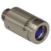 |
These fiber collimation packages are pre-aligned to collimate light from an FC/PC-, FC/APC-, or SMA-terminated fiber. Each collimation package is factory aligned to provide diffraction-limited performance for wavelengths ranging from 405 nm to 4.55 µm. Although it is possible to use the collimator at detuned wavelengths, they will only perform optimally at the design wavelength due to chromatic aberration, which causes the effective focal length of the aspheric lens to have a wavelength dependence. |
| Air-Spaced Doublet, Large Beam Collimators | 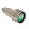 |
For large beam diameters (Ø5.3 - Ø8.5 mm), Thorlabs offers FC/APC, FC/PC, and SMA air-spaced doublet collimators. These collimation packages are pre-aligned at the factory to collimate a laser beam propagating from the tip of an FC or SMA-terminated fiber and provide diffraction-limited performance at the design wavelength. |
| Triplet Collimators |  |
Thorlabs' High Quality Triplet Fiber Collimation packages use air-spaced triplet lenses that offer superior beam quality performance when compared to aspheric lens collimators. The benefits of the low-aberration triplet design include an M2 term closer to 1 (Gaussian), less divergence, and less wavefront error. |
| Achromatic Collimators for Multimode Fiber |  |
Thorlabs' High-NA Achromatic Collimators pair a meniscus lens with an achromatic doublet for high performance across the visible to near-infrared spectrum with low spherical aberration. Designed for use with high-NA multimode fiber, these collimators are ideal for Optogenetics and Fiber Photometry applications. |
| Reflective Collimators | 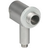 |
Thorlabs' metallic-coated Reflective Collimators are based on a 90° off-axis parabolic mirror. Mirrors, unlike lenses, have a focal length that remains constant over a broad wavelength range. Due to this intrinsic property, a parabolic mirror collimator does not need to be adjusted to accommodate various wavelengths of light, making them ideal for use with polychromatic light. Our fixed reflective collimators are recommended for collimating single and multimode fiber and coupling into multimode fiber. These collimators are available with UV-enhanced aluminum or protected silver reflective coatings and with FC/PC, FC/APC, or SMA connector compatibility. |
| Compact Reflective Collimators | 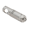 |
Thorlabs' Compact Reflective Collimators incorporate a 90° off-axis parabolic mirror with a protected silver coating. Because the focal length is independent of wavelength for an off-axis parabolic mirror, they are ideal for use with polychromatic light. Our fixed reflective collimators are recommended for collimating single and multimode fiber and coupling into multimode fiber. These collimators are directly compatible with our 16 mm cage system. They are available with FC/PC, FC/APC, or SMA connector inputs. |
| Adjustable Reflective Collimators |  |
Thorlabs' Adjustable Focus Reflective Collimators use a 90° off-axis parabolic (OAP) mirror with a protected silver coating to collimate light from a fiber or couple light into a fiber. The adjustable fiber-to-OAP distance, combined with the OAP having a constant focal length across wavelengths, makes these collimators ideal for optimizing collimation or coupling of polychromatic light with single mode or multimode fiber. These adjustable collimators have a 15.0 mm or 33.0 mm reflected focal length and are available with FC/PC, FC/APC, or SMA connectors. |
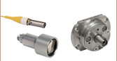
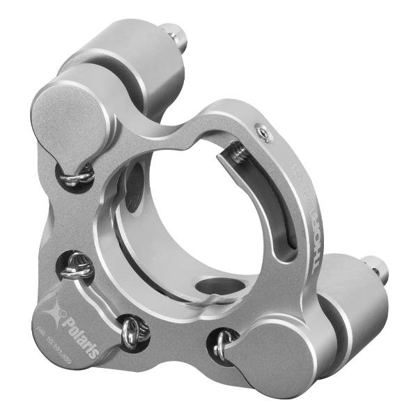
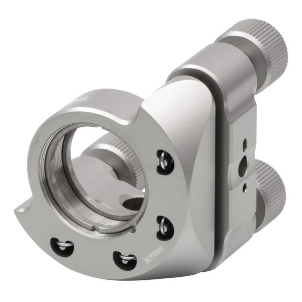
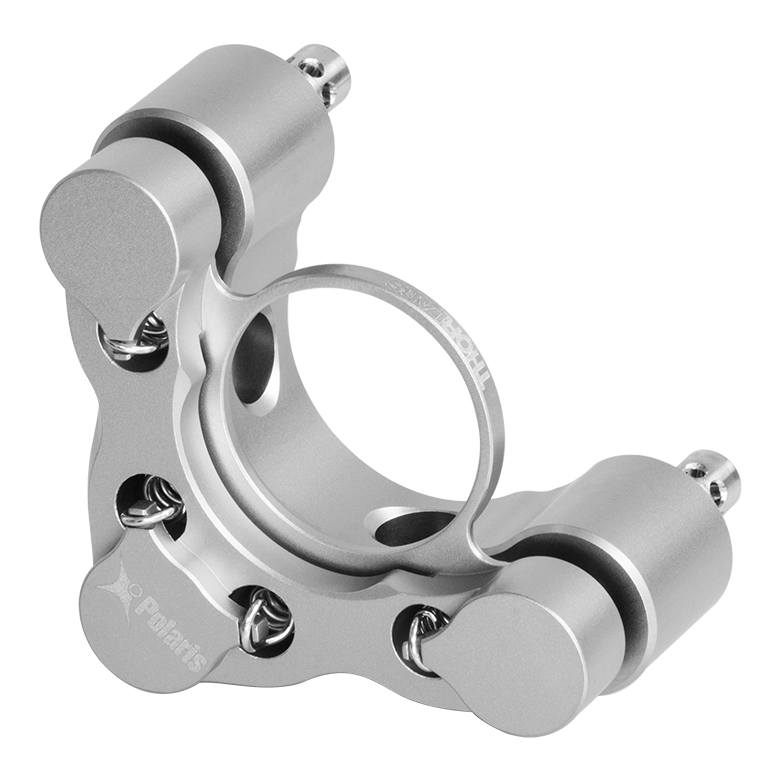
| Polaris Kinematic, Fixed Focus Collimators |  |
Polaris® Kinematic, Fixed Focus Collimators combine the high-quality beam output of our fixed focus collimation packages with the remarkable mechanical properties of our Polaris® mounts, making them the ultimate solution for fiber collimation applications requiring stringent long-term alignment stability. These fiber collimation packages are pre-aligned to collimate light from an FC/PC-terminated fiber with diffraction-limited performance at one of four alignment wavelengths between 532 nm and 850 nm. |
| FiberPorts |  |
These compact, ultra-stable FiberPort micropositioners provide an easy-to-use, stable platform for coupling light into and out of FC/PC, FC/APC, or SMA terminated optical fibers. It can be used with single mode, multimode, or PM fibers and can be mounted onto a post, stage, platform, or laser. The built-in aspheric or achromatic lens is available with five different AR coatings and has five degrees of alignment adjustment (3 translational and 2 pitch). The compact size and long-term alignment stability make the FiberPort an ideal solution for fiber coupling, collimation, or incorporation into OEM systems. |
| Adjustable Fiber Collimators |  |
These collimators are designed to connect onto the end of an FC/PC, FC/APC, or SMA connector and contain an AR-coated aspheric lens. The distance between the aspheric lens and the tip of the fiber can be adjusted to compensate for focal length changes or to recollimate the beam at the wavelength and distance of interest. |
| Achromatic Fiber Collimators with Adjustable Focus | 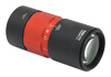 |
Thorlabs' Achromatic Fiber Collimators with Adjustable Focus are designed with an effective focal length (EFL) of 20 mm, 40 mm, or 80 mm, have optical elements broadband AR coated for one of three wavelength ranges, and are available with FC/PC, FC/APC, or SMA905 connectors. A four-element, air-spaced lens design produces superior beam quality (M2 close to 1) and less wavefront error when compared to aspheric lens collimators. These collimators can be used for free-space coupling into a fiber, collimation of output from a fiber, or in pairs for collimator-to-collimator coupling over long distances, which allows the beam to be manipulated prior to entering the second collimator. |
| Zoom Fiber Collimators | 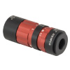 |
These collimators provide a variable focal length between 6 and 18 mm, while maintaining the collimation of the beam. As a result, the size of the beam can be changed without altering the collimation. This universal device saves time previously spent searching for the best suited fixed fiber collimator and has a very broad range of applications. They are offered with FC/PC, FC/APC, or SMA905 connectors with three different antireflection wavelength ranges to choose from. |
| Single Mode Pigtailed Collimators | 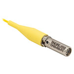 |
Our single mode pigtailed collimators come with one meter of fiber, consist of an AR-coated aspheric lens pre-aligned with respect to a fiber, and are collimated at one of eight wavelengths: 532 nm, 633 nm, 780 nm, 850 nm, 1030 nm, 1064 nm, 1310 nm, or 1550 nm. Although it is possible to use the collimator at any wavelength within the coating range, the coupling loss will increase as the wavelength is detuned from the design wavelength. |
| Polarization Maintaining Pigtailed Collimators | 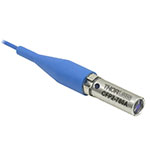 |
Our polarization maintaining pigtailed collimators come with one meter of fiber, consist of an AR-coated aspheric lens pre-aligned with respect to a fiber, and are collimated at one of five wavelengths: 633 nm, 780 nm, 980 nm, 1064 nm, or 1550 nm. Custom wavelengths and connectors are available as well. A line is engraved along the outside of the housing that is parallel to the fast axis. As such, it can be used as a reference when polarized light is launched accordingly. Although it is possible to use the collimator at any wavelength within the coating range, the coupling loss will increase as the wavelength is detuned from the design wavelength. |
| GRIN Fiber Collimators | 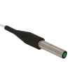 |
Thorlabs offers gradient index (GRIN) fiber collimators that are aligned at a variety of wavelengths from 630 to 1550 nm and have either FC terminated, APC terminated, or unterminated fibers. Our GRIN collimators feature a Ø1.8 mm clear aperture, are AR-coated to ensure low back reflection into the fiber, and are coupled to standard single mode or graded-index multimode fibers. |
| GRIN Lenses |  |
These graded-index (GRIN) lenses are AR coated for applications at 630, 830, 1060, 1300, or 1560 nm that require light to propagate through one fiber, then through a free-space optical system, and finally back into another fiber. They are also useful for coupling light from laser diodes into fibers, coupling the output of a fiber into a detector, or collimating laser light. Our GRIN lenses are designed to be used with our Pigtailed Glass Ferrules and GRIN/Ferrule sleeves. |
Thorlabs offers several different general varieties of Polaris mounts, including kinematic side optic retention, SM-threaded, low optic distortion, piezo-actuated, vertical drive, and glue-in optic mounts, a fixed monolithic mirror mount and fixed optic mounts, XY translation mounts, 5-axis kinematic mount, a kinematic platform mount, and kinematic, fixed focus collimators. Refer to the tables below for our complete line of Polaris mounts, grouped by mount type, optic bore size, and then arranged by optic retention method and adjuster type (or intended application in the case of fixed mounts). We also offer a line of accessories that have been specifically designed for use with our Polaris mounts; these are listed in Table 103H. Note that the tables below list Item # suffixes that omit the "POLARIS" prefix for brevity. Click the photos below for details.
| Table 103A Polaris Mount Optic Retention Methods | |||
|---|---|---|---|
| Side Lock | SM Threaded | Low Distortion | Glue-In |
 |
 |
 |
 |
| Table 103B Polaris Mount Adjuster Types | |||||
|---|---|---|---|---|---|
| Side Hole | Hex | Adjuster Knobs | Adjuster Lock Nuts |
Piezo Adjusters | Vertical-Drive Adjusters |
 |
 |
 |
 |
 |
 |
| Table 103C Polaris Kinematic Mounts for Round Optics | ||||
|---|---|---|---|---|
| Optic Retention Method | Side Lock | SM Threaded | Low Distortion | Glue-In |
| Ø1/2" Optics | ||||
| 2 Side Hole Adjusters | - | - | - | -K05C4 -K05G4 |
| 2 Hex Adjusters | -K05S1 | -K05T1 | -K05F1 | - |
| 2 Adjusters with Lock Nuts | -K05S2 | -K05T2 | -K05F2 | - |
| 2 Piezoelectric Adjusters | -K05P2 | - | - | - |
| 2 Vertical Adjusters | -K05VS2 -K05VS2L |
- | - | - |
| 3 Hex Adjusters | -K05 | - | - | - |
| 3 Adjusters with Lock Nuts | - | -K05T6 | -K05F6 | - |
| 3 Adjuster Knobs (Tip/Tilt/Z) & 2 Hex Adjusters (X/Y) |
- | -K05XY | - | - |
| Ø19 mm (3/4") Optics | ||||
| 2 Side Hole Adjusters | -K19S4 | - | -K19F4/M | -K19G4 |
| Ø25 mm Optics | ||||
| 2 Side Hole Adjusters | -K25S4/M | - | -K25F4/M | - |
| Ø1" Optics | ||||
| 2 Side Hole Adjusters | -K1S4 | - | - | -K1C4 -K1G4 |
| 2 Hex Adjusters | -K1E2 -K1-2AH |
-K1T2 | -K1F2 | - |
| 2 Adjuster Knobs | - | -K1T1 | -K1F1 | - |
| 2 Piezoelectric Adjusters | -K1S2P | - | - | - |
| 2 Vertical Adjusters | -K1VS2 -K1VS2L |
- | - | - |
| 3 Side Hole Adjuster | -K1S5 | - | - | - |
| 3 Hex Adjusters | -K1E3 -K1-H |
-K1T3 | - | - |
| 3 Adjuster Knobs | -K1E -K1 |
-K1T | -K1F | - |
| 3 Piezoelectric Adjusters | -K1S3P | - | - | - |
| 3 Adjuster Knobs (Tip/Tilt/Z) & 2 Hex Adjusters (X/Y) |
- | -K1XY | - | - |
| Optic Retention Method | Side Lock | SM Threaded | Low Distortion | Glue-In |
| Ø1.5" Optics | ||||
| 2 Side Hole Adjusters | -K15S4 | - | -K15F4 | - |
| 2 Vertical Adjusters | -K15VS2 -K15VS2L |
- | - | - |
| 3 Adjuster Knobs (Tip/Tilt/Z) & 2 Hex Adjusters (X/Y) |
- | -K15XY | - | - |
| Ø50 mm Optics | ||||
| 2 Side Hole Adjusters | -K50S4/M | - | -K50F4/M | - |
| Ø2" Optics | ||||
| 2 Hex Adjusters | -K2S2 | -K2T2 | -K2F2 | - |
| 2 Adjuster Knobs | -K2S1 | -K2T1 | -K2F1 | - |
| 2 Piezoelectric Adjusters | -K2S2P | - | - | - |
| 2 Vertical Adjusters | -K2VS2 -K2VS2L |
- | - | - |
| 3 Hex Adjusters | -K2S3 | -K2T3 | -K2F3 | - |
| 3 Adjuster Knobs | -K2 | -K2T | -K2F | - |
| Ø3" Optics | ||||
| 2 Side Hole Adjusters | -K3S4 | - | - | - |
| 3 Side Hole Adjusters | -K3S5 | - | - | - |
| Ø4" Optics | ||||
| 2 Side Hole Adjusters | - | - | -K4F4 | - |
| Ø6" Optics | ||||
| 2 Side Hole Adjusters | - | - | -K6F4 | - |
| Table 103D Polaris XY Translation Mounts for Round Optics | ||
|---|---|---|
| Optic Retention Method | SM Threaded | Representative Photos |
| Ø1/2" Optics |   |
|
| 2 Hex Adjusters (X/Y) | -05CXY | |
| -05XY | ||
| 3 Adjuster Knobs (Tip/Tilt/Z) & 2 Hex Adjusters (X/Y) |
-K05XY | |
| Ø1" Optics | ||
| 2 Hex Adjusters (X/Y) | -1XY | |
| 3 Adjuster Knobs (Tip/Tilt/Z) & 2 Hex Adjusters (X/Y) |
-K1XY | |
| Ø1.5" Optics | ||
| 2 Hex Adjusters (X/Y) & 3 Adjuster Knobs (Tip/Tilt/Z) |
-K15XY | |
| Table 103E Polaris Fixed Mounts for Round Optics | ||||||
|---|---|---|---|---|---|---|
| Optic Retention Method | Side Lock | Low Distortion |
Glue-In | Representative Photos |
||
| Ø1/2" Optics | 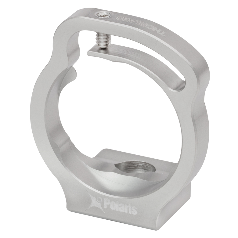   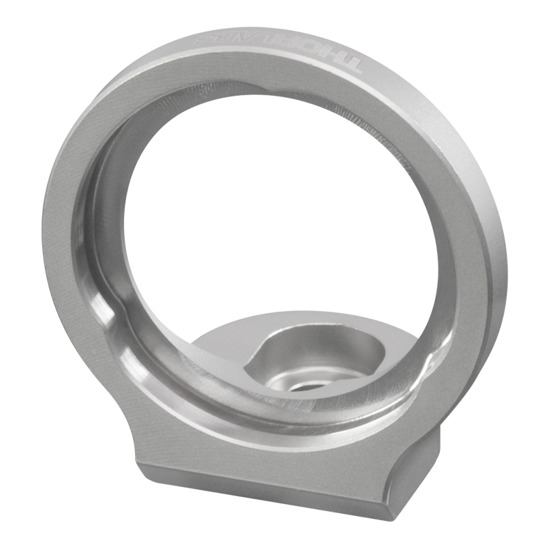 |
|||||
| Optimized for Mirrors | - | -B05F | -C05G | |||
| Optimized for Beamsplitters | -B05S | - | -B05G | |||
| Optimized for Lenses | - | - | -L05G | |||
| Ø19 mm (Ø3/4") Optics | ||||||
| Optimized for Mirrors | -19S50/M | - | - | |||
| Ø1" Optics | ||||||
| Optimized for Mirrors | - | -B1F | -C1G | |||
| Optimized for Beamsplitters | -B1S | - | -B1G | |||
| Optimized for Lenses | - | - | -L1G | |||
| Ø2" Optics | ||||||
| Optimized for Mirrors | - | -B2F | -C2G | |||
| Optimized for Beamsplitters | -B2S | - | - | |||
| Table 103F Polaris Kinematic 1.8" x 1.8" Platform Mount | ||
|---|---|---|
| Adjustment Method | Item # Suffix | 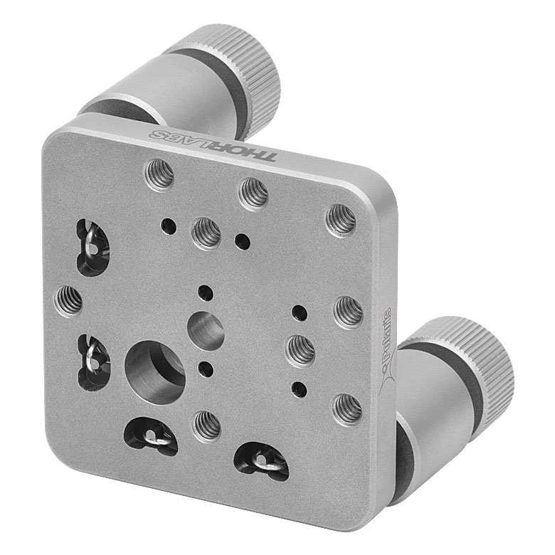 |
| 2 Adjuster Knobs | -K1M4(/M) | |
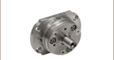
| Table 103G Polaris Kinematic, Fixed Focus Collimators | ||
|---|---|---|
| Adjustment Method | Item #s | Representative Photo |
| 2 Side Hole Adjusters | PF2F53(/M) PF2F63(/M) PF2F78(/M) PF2F85(/M) |
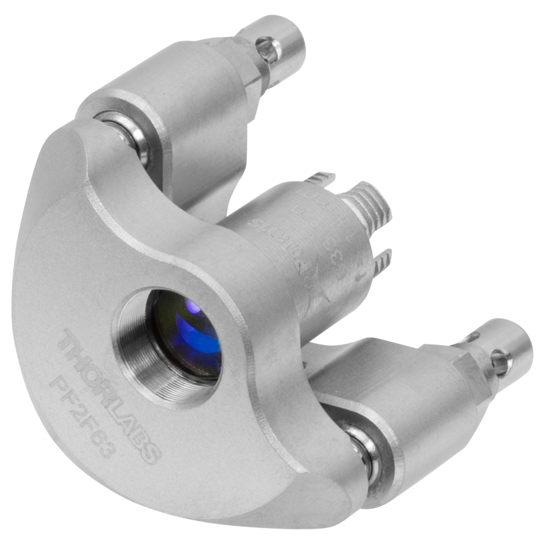 |
| Table 103H Accessories for Polaris Mounts | |
|---|---|
| Description | Representative Photos |
| Ø1/2" Posts for Polaris Mounts |  |
| Ø1" Posts for Polaris Mounts | |
| Non-Bridging Clamping Arms | 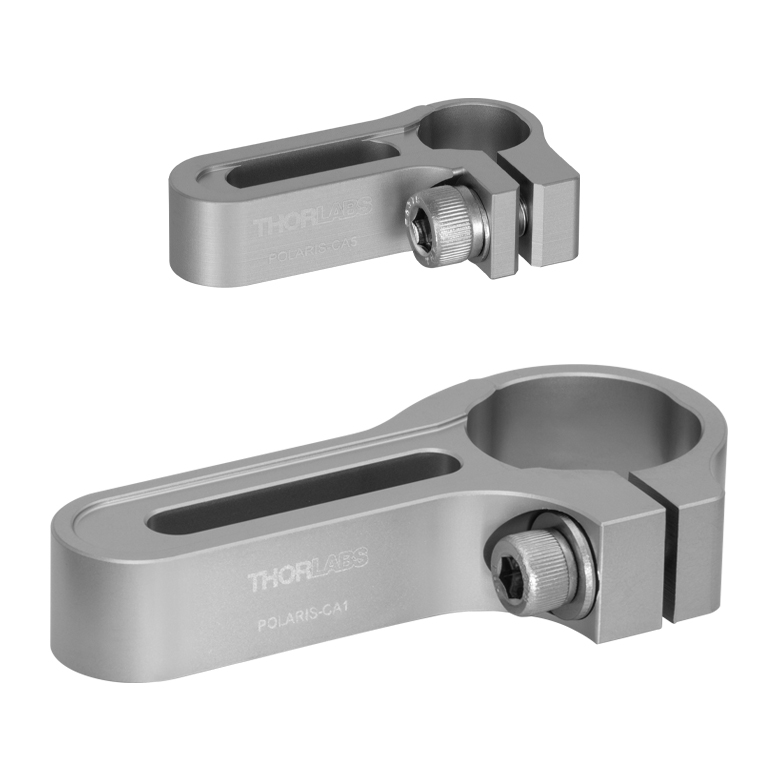 |
| 45° Mounting Adapter |  |
| Posted Comments: | |
| No Comments Posted |
| Item # | Alignment Wavelengtha |
AR Coating |
Full-Angle Beam Divergenceb | Focal Lengthc | NA | Connectors | Adjuster Drive | Adjuster Pitch |
|---|---|---|---|---|---|---|---|---|
| PF2F53(/M) | 532 nm | Ravg < 0.5%, 350 - 700 nm |
0.02° | 10.90 mm | 0.25 | FC/PC, Three 2.2 mm Wide Key Slotsd |
5/64" (2.0 mm) Hex, Ø0.07" (Ø1.8 mm) Side Adjustment Holes | 3/16"-130 Matched Actuator/Body Pairs |
| PF2F63(/M) | 633 nm | Ravg < 0.5%e, 650 - 1050 nm |
0.022° | 10.99 mm | ||||
| PF2F78(/M) | 780 nm | Ravg < 0.5%, 650 - 1050 nm |
0.026° | 11.07 mm | 0.26 | |||
| PF2F85(/M) | 850 nm | 0.03° | 11.12 mm | 0.25 |

 Zoom
ZoomVideo 633B To install a lock nut without cross threading, gently place the lock nut against the end of the adjuster. "Unscrew" the nut until the threads of the nut and the adjuster align before threading the nut onto the adjuster. This animation shows the installation of a POLARIS-LN1 lock nut on a
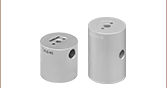
- Provide Long Term Adjuster Stability
- Compatible with Select Polaris Mounts
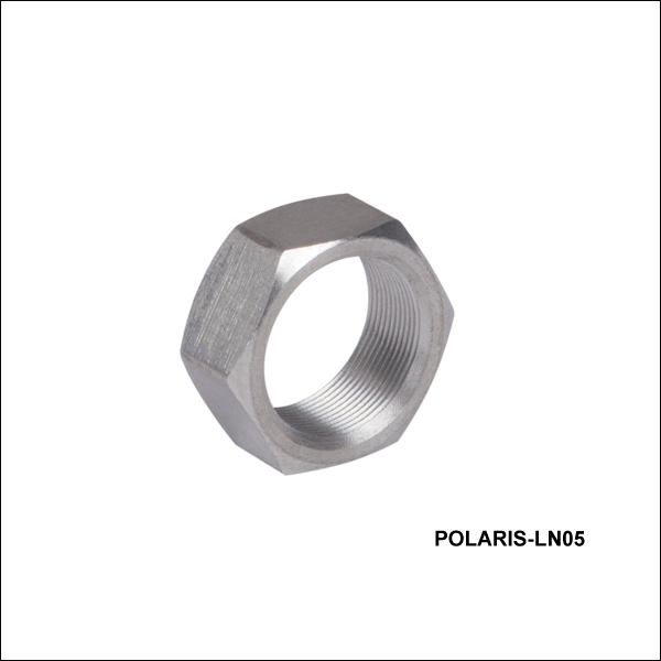
These lock nuts are designed for use with Polaris mounts with 3/16"-130 adjusters. Designed for long-term adjuster stability or applications that are exposed to shock and vibration, these lock nuts are pre-greased with the same ultra-high-vacuum-compatible, low-outgassing PTFE grease as the Polaris mounts and have been tested for adjuster fit.
For applications that require frequent tuning of the adjusters, the lock nuts only need to be lightly tightened by hand to a torque of approximately 4 to 8 oz-in (0.03 to 0.06 N·m). For long term stability, we recommend tightening to a torque of 24 oz-in, which can be achieved by using our TW6 preset torque wrench (sold below). POLARIS-LN05 lock nuts require a 6 mm hex tool for tightening. To avoid cross threading the lock nut, place it against the adjuster and "unscrew" the lock nut until you feel a slight drop; then thread the lock nut onto the adjuster.

 Zoom
Zoom- Provides Long-Term Adjuster Stability
- Compatible with Select Polaris Mounts
- Low Profile: Ø0.25" (Ø6.4 mm) x 0.05" (1.3 mm) Thick
- Tighten Along Rotational Axis Using the POLARIS-T3 Spanner Wrench
The POLARIS-LNS05 locking collar is compatible with Polaris mounts that have 3/16"-130 adjusters, excluding the piezo-driven mounts and mounts with low-profile adjusters (Item #s POLARIS-K05 and POLARIS-K05S1). Designed for long-term adjuster stability or applications that are exposed to shock and vibration, these locking collars are pre-greased with the same ultra-high-vacuum-compatible, low-outgassing PTFE grease as the Polaris mounts and have been tested for adjuster fit.
The POLARIS-T3 spanner wrench has been specifically designed for use in securing the POLARIS-LNS05 locking collar. The double spanner head enables complete engagement while the design allows locking collar adjustments to be along the same line as the adjuster itself. A center through hole allows a 2 mm ball driver to pass through the spanner wrench, so that the adjuster can be held in position while the locking collar is engaged.
For applications that require frequent tuning of the adjusters, the locking collar only needs to be lightly tightened to a torque of approximately 4 to 8 oz-in (0.03 to 0.06 N·m). For long-term stability, we recommend tightening to a torque of 32 oz-in, which can be achieved by using our TW13 preset torque wrench (sold below) in combination with the POLARIS-T3 spanner wrench. To avoid cross threading the locking collar, place it against the adjuster and "unscrew" the collar until you feel a slight drop; then thread the collar onto the adjuster.

 Zoom
Zoom
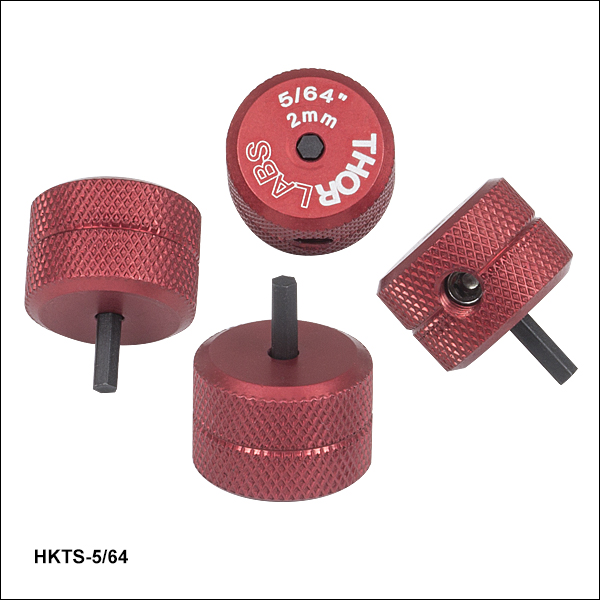
- For Convenient Adjustment of 5/64" and 2 mm Hex-Driven Actuators
- Red Anodized Adjustment Knob with Engraved Hex Size
- Replaceable Hex Tip
- Sold in Packages of 4
These 5/64" Hex Key Adjuster Thumbscrews allow for quick adjustment of many 5/64" and 2 mm hex-driven actuators (or standard actuators with the knobs removed). These temporary knobs can be left in the screw's hex socket between adjustments for convenience (see Figure 206A). An 8-32 setscrew (5/64" hex) secures the replaceable hex bit, which can be reversed if the tip is stripped. Contact Tech Sales to order replacement hex key bits.
We offer hex key thumbscrews in sizes from 0.050" to 3/16" and 2 mm to 5 mm.

 Zoom
Zoom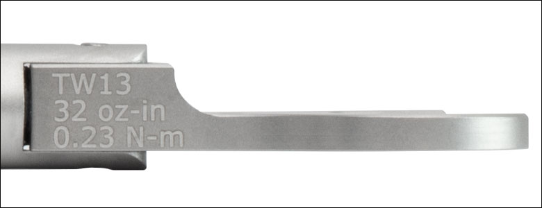
Click to Enlarge
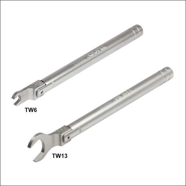
Figure 676A Each wrench is engraved with its preset torque value and Item #.
Click for Details
Figure 676B TW6 Torque Wrench Used to Secure POLARIS-LN05 Lock Nut on POLARIS-K05T2 Mirror Mount
- Preset Wrenches for Polaris Lock Nuts & Spanner Wrenches (See Table 676C for Compatibility):
- TW6: 6 mm Hex, 24 oz-in
- TW13: 13 mm Hex, 32 oz-in
- Break-Over Design Ensures Proper Torque is Applied
- Ideal for Applications Requiring Long-Term Locking
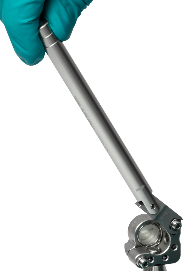
These torque wrenches have a preset torque value to secure the lock nuts on Polaris mounts for long-term locking; see Table 676C for specifications. When the preset torque value has been achieved, the break-over design will cause the pivoting joint to "break," as shown in Figure 676B. The wrench's hex head will move back into place once the force is removed. This design prevents further force from being applied to the lock nut. Engraved guidelines indicate the angle the wrench should pivot in order to apply the specified torque; pivoting the handle past these guidelines will over-torque the lock nut. Each wrench is also engraved with its preset torque value, torque direction, wrench size, and Item # for easy identification in the field.
These wrenches are designed to be compatible with cleanroom and vacuum chamber applications. They are chemically cleaned using the Carpenter AAA passivation method to remove sulfur, iron, and contaminants from the surface. After passivation, they are assembled in a clean environment and double vacuum bagged to eliminate contamination when transported into a cleanroom. Every wrench has a bead-blasted finish to minimize reflections when working with setups that include lasers.
Please note that these wrenches are not intended for use in applications where adjusters are frequently tuned, as these applications typically require torque values of 4 to 8 oz-in (0.03 to 0.06 N·m).
| Table 676C Specifications | ||||
|---|---|---|---|---|
| Item # | Hex | Torque | Torque Accuracy | Compatible Items |
| TW6 | 6 mm | 24 oz-in (0.17 N•m) | ±1.44 oz-in (0.010 N•m) | LN19100H 3/16"-100 Aluminum Lock Nut, POLARIS-LN05 3/16"-130 Stainless Steel Lock Nut |
| TW13 | 13 mm | 32 oz-in (0.23 N•m) | ±1.92 oz-in (0.014 N•m) | POLARIS-LN1 1/4"-100 Stainless Steel Lock Nut POLARIS-LN4 3/8"-100 Stainless Steel Lock Nut POLARIS-T2 Spanner Wrench for POLARIS-LNS1 Locking Collar POLARIS-T3 Spanner Wrench for POLARIS-LNS05 Locking Collar |