 Products Home
Upright Confocal Microscopy Systems

- Complete Upright Confocal Imaging Microscopes
- Up to 4 Channels of Excitation/Emission
- Supports Widefield and Laser Scanning Imaging
Each Confocal Microscopy System includes a computer, DAQ, and ThorImage®LS Data Acquisition Software. The optical table is sold separately.


Please Wait

Sam Tesfai
General Manager,
Thorlabs Imaging Systems
Questions?
Feedback?
Need a Quote?
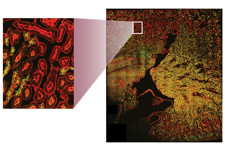
Click to Enlarge
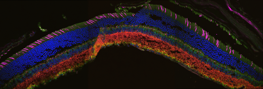
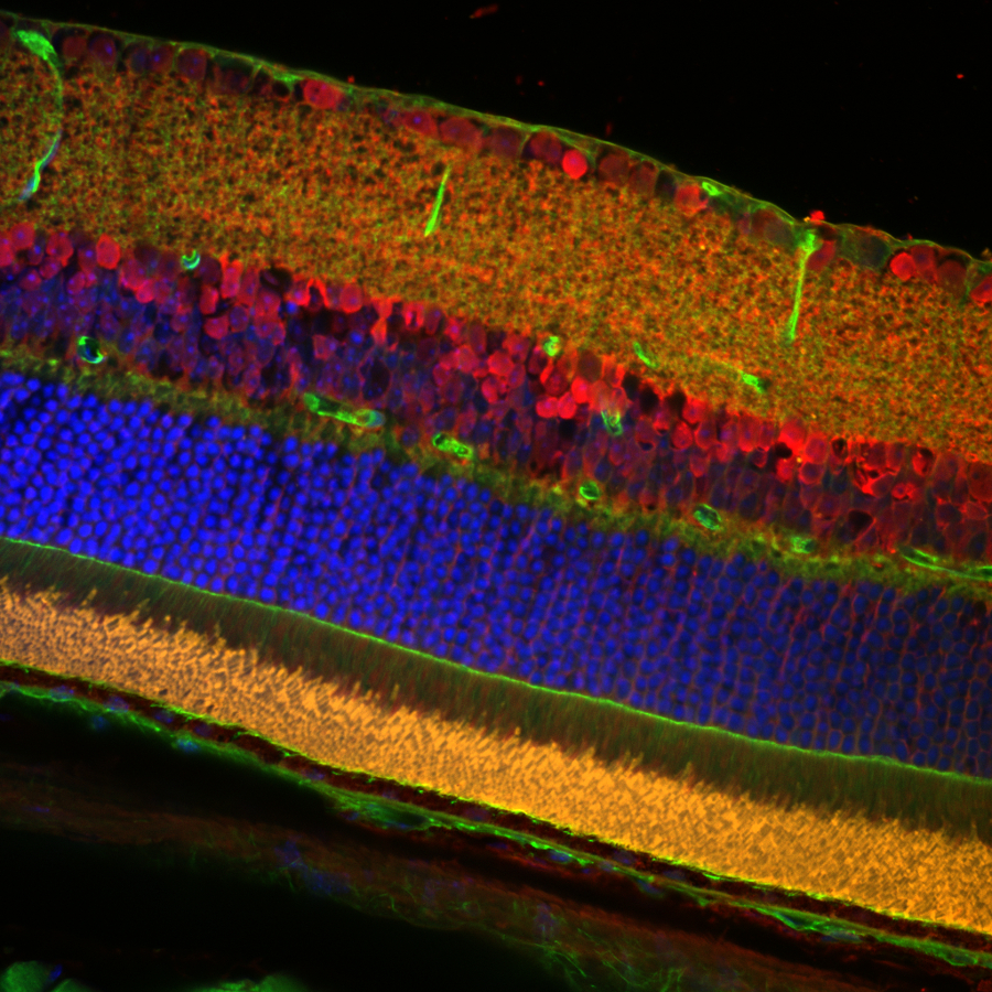
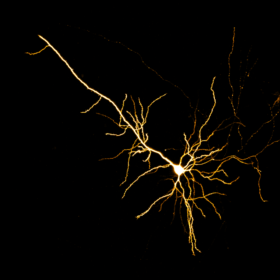
Figure 1.1 Stitched Image of Cell Layers in Mouse Retina
Sample Courtesy of Robert Fariss, Biological Imaging Core, NIH, Bethesda, Maryland


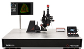
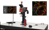
Thorlabs' Confocal Microscopy System
- Complete Upright Confocal Imaging Systems
- Up to 4 Channels of Excitation in a Monolithic, Fiber-Coupled Laser Source
- Up to 4 Channels of Detection with Multialkali, High-Sensitivity GaAsP PMTs, or Si Photomultiplier (SiPM) Amplified Detectors
- Galvo-Galvo or Galvo-Resonant Scanners
- Full-Frame 4096 x 4096 Pixel Images
- 2048 x 2048 Pixels (Bi-Directional)
- 4096 x 4096 Pixels (Uni-Directional)
- Motorized Pinhole Wheel with 16 Sizes of Round Pinholes
- ThorImage®LS Data Acquisition Software with Lifetime Support
- Upright Microscope Body System to Support Future Expansion
- Widefield Viewing Accessories
- DIC or Dodt Contrast Imaging
- XY Movement of Microscope and/or Sample
Thorlabs' Upright Confocal Microscopy Systems are complete, fully equipped microscopes available with galvo-galvo or galvo-resonant scan heads to support a variety of imaging applications. By eliminating signals that originate from outside the focal plane, confocal microscopy provides the ability to acquire high-resolution, optically sectioned images from within a thick sample or to reduce background fluorescence from thin cultures. Each system is tailored to meet individual imaging requirements; contact us using the Contact Me button in the green box for additional information and to receive a quote.
For applications that require rapid imaging of live systems, our 8 kHz and 12 kHz galvo-resonant scan heads offer frame rates up to 400 fps and 600 fps, respectively. Alternatively, microscopes with galvo-galvo scanners are ideal for experiments involving photo-uncaging. The fiber-coupled laser source can be configured with up to four channels with wavelengths from 400 to 1310 nm. A motorized pinhole wheel with 16 round pinholes provides true diffraction-limited imaging while allowing the user to optimize the pinhole size for their objective. Multi-spectral imaging is enabled by a two- or four-channel detection module with an included filter set that, together with the laser source, has been optimized for the excitation and emission wavelengths of popular fluorophores. Choose from standard multialkali photomultiplier tubes (PMTs) for samples with a large dynamic range, high-sensitivity GaAsP PMTs to image weakly fluorescent samples, or silicon photomultiplier (SiPM) amplified detectors with high-sensitivity and dynamic range.
Each microscope includes a PC with DAQ card and the ThorImageLS data acquisition software. ThorImageLS was developed in conjunction with our laser scanning microscopy systems to provide a seamless, logical, intuitive program for acquiring and analyzing images. This software package enables synchronization of external hardware and events, multi-dimensional data acquisition and display, region-of-interest scanning, and multi-user operation. All images are saved in the standard TIFF image format so that they can be viewed using software packages such as ImageJ/Fiji. See the ThorImageLS tab for additonal information on ThorImageLS features. Upon the purchase of a confocal system, Thorlabs provides lifetime support for the ThorImageLS package.
For more information on the system configurations, see the Confocal System tab. For system specifications, please see the Specs tab.
Thorlabs recognizes that each imaging application has unique requirements.
If you have any feedback, questions, or need a quotation, please contact ImagingSales@thorlabs.com or call (703) 651-1700.
| Quick Links |
|---|
| Confocal Scanner |
| Laser Excitation |
| Image Detection |
Thorlabs' Confocal Microscopy System
Thorlabs’ Upright Confocal Laser Scanning Microscopy Systems consist of an upright microscope body with a galvo-galvo or galvo-resonant scanner, monolithic laser source, multi-channel detection module control electronics, pinhole wheel, and all fibers and cables needed to interconnect the system. All hardware components are directly controlled by ThorImage®LS software, including automated Z-step control for optical sectioning (via a piezo or stepper motor) and automatic calculation of Airy disk units based on the combination of the objective magnification and pinhole size; the intuitive interface allows novice and experienced users alike to obtain high-resolution microscope images quickly and easily.
Thorlabs' applications engineers install each confocal system and are available to address technical problems that may occur; for additional information, please see our Confocal Microscopy Contact Form.
Scanner
At the heart of our systems is a confocal scan head that can be configured with galvo-galvo or galvo-resonant scanners. Galvo-galvo scanners allow specific regions of interest to be targeted for experiments requiring photo-uncaging, while galvo-resonant scanners support high imaging speeds of up to 400 frames per second (at 512 x 32 pixel resolution). Both types of scanners can create full frame images with high spatial resolution of up to 4096 x 4096 pixels. At either extreme, or anywhere in-between, the control and acquisition system creates high-quality, jitter-free images.
The confocal scan path is integrated with a microscope body based on our Cerna® Modular Microscopy System, allowing the system to be customized with widefield imaging accessories upon request. A D1N dovetail on top of the scan path accepts single or double camera ports for scientific cameras, trinoculars, and epi-illuminators. A 95 mm dovetail along the length of the body accepts sample holders including a Z-axis piezo stage, condenser modules, or transmitted illumination modules for brightfield, Dodt contrast, or DIC imaging. In the most basic configuration, a mirror on a manual slider at the front of the scan path allows the user to switch between confocal and widefield imaging modalities. This optic can be upgraded to a dichroic or beamsplitter and the manual slider upgraded to a motorized one.
Our complete systems come standard with a primary dichroic that is optimized to reflect the specific laser lines used. Other primary dichroics for use with other wavelengths can be provided upon request.
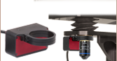
Click to Enlarge
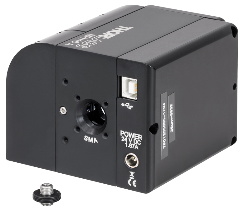
Figure 2.1 Our A-coated motorized filter wheel shown disconnected from the confocal scan head with the SMA fiber connector removed for free-space output.
Motorized Pinhole Wheel
A motorized pinhole wheel allows the pinhole size to be adjusted for a variety of imaging configurations and objective numerical apertures in order to simultaneously maximize the in-focus light that reaches the detectors and minimize the transmission of signal from outside the focal plane. A rotating glass plate has 16 sizes of lithographic round pinholes deposited to exceedingly tight tolerances, ensuring that optimal alignment is maintained as each pinhole is rotated into the light path.
For thicker samples, the size of the pinhole should be optimized relative to the NA of the objective in order to maximize the signal to noise ratio. With this in mind, our engineers selected each pinhole size to complement a common objective NA. Conversely, for thinner samples that produce less light outside of the focal plane, a larger pinhole size can help improve throughput. Pinhole diameters up to 2 mm provide flexibility so that the system can be easily adapted to different experiments.
A round pinhole is the ideal shape for maximizing the transmission of light generated in the focal plane of your sample while also optimizing the rejection of signal generated above and below the layer that is being scanned.
The pinhole is conveniently powered and controlled via USB. Additionally, the motorized, encoded control of the pinhole ensures perfect alignment and vibration-free movement. The emitted light from the specimen is focused on the pinhole by an achromatic doublet and then collected by a large-core multimode fiber for transmission to the detector system. To maximize transmission at the desired emission wavelengths, three AR coating options are available for the achromatic doublet.
Excitation and Emission
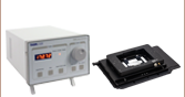
The solid state multi-laser source minimizes maintenance with an all-fiber design. Each laser line is individually fiber-coupled using a permanent rigid system. The individual fiber-coupled lasers are then combined in an all-fiber coupler with an FC/PC connector. This design ensures the lasers never go out of alignment keeping the full power of the lasers coupled to the scan head at all times. The system can also be configured with a free-space laser source upon request by contacting ImagingSales@thorlabs.com. The laser source is controlled by a controller box, which includes a safety interlock system and manual control of laser emission. The laser source can also be controlled remotely by way of an auxiliary input.
Each confocal system also includes a filter set optimized for the chosen excitation and emission wavelengths.
Detection
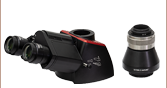
Click to Enlarge
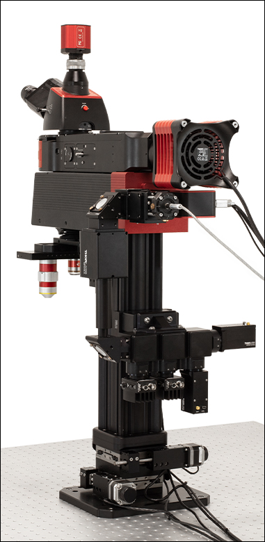
Figure 2.3 The Upright Confocal Microscope System can be configured to have the detector module mounted on the back of the system using the 95 mm rail. The detector module shown has two SiPMs and two PMTs attached.
Click to Enlarge
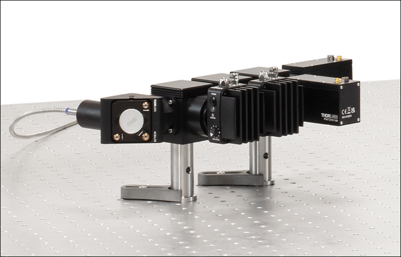
Figure 2.2 The detector module features ports for up to four detectors and can be customized to use Thorlabs' multialkali PMTs, GaAsP PMTs, or SiPM detectors. The filter sets are mounted in dichroic filter cubes for easy exchange.
Detector: Future-proof your experiments with our positioned detector module that can be readily expanded from two to four PMTs or SiPMs. Sitting in front of each detector is a quickly exchangeable dichroic mirror and emission filter holder. The detector module can be mounted to an optical table away from the microscope or directly to the microscope as shown in Figures 2.2 and 2.3, respectively.
The detection module can be configured with our standard sensitivity multialkali PMTs, high sensitivity, ultra-low-noise GaAsP PMTs, or our high-sensitivity and dynamic range SiPMs. The standard sensitivity multi-alkali PMTs provide a low-noise image with high dynamic range that is appropriate for most life-science and industrial applications. For weakly fluorescent or highly photosensitive samples, we also offer the option of high-sensitivity, TEC-cooled GaAsP PMTs. While our SiPM detectors are ideal for applications that require a high sensitivity and large dynamic range. With any choice of detector, the gain as well as the dynamic range of the digitizer is controlled within the ThorImageLS software.
Filters: Each confocal upgrade includes an appropriate set of emission filters that block laser light from reaching the detector and provide pass bands at the fluorescence wavelengths of popular fluorophores. The exact configuration is determined by the laser wavelengths in your confocal system. If you have questions concerning the filter set included with a specific laser configuration, please contact ImagingSales@thorlabs.com for more information.
Computer: Each confocal system includes a 64-bit computer with a 24" monitor. The included ThorImageLS software package provides an all-in-one solution for microscope control, automated data collection, and image review. See the ThorImageLS tab for more information.
Thorlabs recognizes that each imaging application has unique requirements.
If you have any feedback, questions, or need a quotation, please contact ImagingSales@thorlabs.com or call (703) 651-1700.
Specifications for Thorlabs' Confocal System are provided in Table 3.1. For a description of the available modules, see the Confocal System tab. For more information, contact our sales team and applications engineers at ImagingSales@thorlabs.com or (703) 651-1700.
| Table 3.1 Specifications | ||
|---|---|---|
| Excitation | ||
| Laser Source Options | Channels | Up to 4 |
| Wavelength Range | 400 to 1310 nma | |
| Primary Dichroic Mirror | Quad-Band Dichroic Beamsplitter (Other Dichroics Available upon Request) |
|
| Scanning | ||
| Scan Head | Galvo-Resonant with Resonant Scanner (X) and Galvo Scan Mirror (Y) or Galvo-Galvo | |
| Galvo Scanning Speed | 8 kHz Galvo-Resonant | 30 Frames per Second at 512 x 512 Pixels 400 Frames per Second at 512 x 32 Pixels 2 Frames per Second at 4096 x 4096 Pixels |
| 12 kHz Galvo-Resonant | 4.4 fps at 2048 x 2048 Pixels 45 fps at 512 x 512 Pixels 600 fps at 512 x 32 Pixels |
|
| Galvo-Galvo | 3 fps at 512 x 512 Pixels 48 fps at 512 x 32 Pixels 70 fps at 32 x 32 Pixels Pixel Dwell Time: 0.4 to 20 µs |
|
| Galvo-Galvo Scan Modes | Imaging | Line, Polyline, Square, or Rectangle |
| Non-Imaging | Circle, Ellipse, Polygon, or Point | |
| Scan Zoom | Up to 2048 x 2048 Bi-Directional Acquisition; Up to 4096 x 4096 Uni-Directional Acquisition 1X - 16X (Continuous) |
|
| Digitization / Sampling Density | Up to 2048 x 2048 Bi-Directional Acquisition; Up to 4096 x 4096 Uni-Directional Acquisition | |
| Diffraction-Limited Field of View (FOV) | 1 mm x 1 mm at 400 - 750 nmb 600 µm x 600 µm at 680 - 1300 nmb |
|
| Emission | ||
| Detectors | Standard Multialkali PMT, High-Sensitivity GaAsP PMT, or Silicon Photomultiplier (SiPM) Amplified Detector | |
| Detection Channels | Up to 4 | |
| Filtersc | Emission Filter Set and Longpass Dichroic to Complement Multi-Channel Laser Source | |
| Confocal Imaging | ||
| Motorized Pinhole Wheel with 16 Round Pinholes from Ø25 µm to Ø2 mm Two to Four Laser Lines (488 nm Standard; Other Options Range from 405 nm to 660 nm) Standard Multialkali PMT, High-Sensitivity GaAsP PMT, or High-Dynamic Range SiPMs Easy-to-Exchange Emission Filters and Dichroic Mirrors |
||
| Widefield Viewing | ||
| Manual or Motorized Switching Between Scanning and Widefield Modes Illumination Provided via LED or Liquid Light Guide C-Mount Threads for Scientific Cameras |
||
Thorlabs recognizes that each imaging application has unique requirements.
If you have any feedback, questions, or need a quotation, please contact ImagingSales@thorlabs.com or call (703) 651-1700.
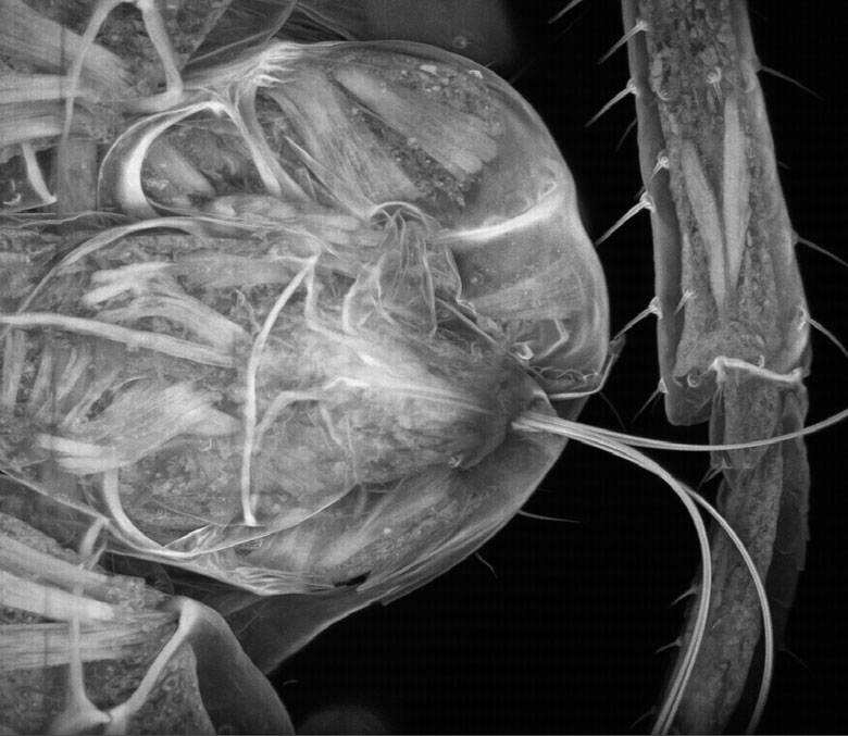
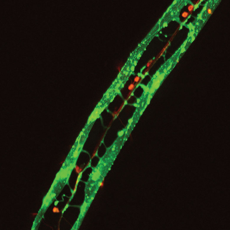
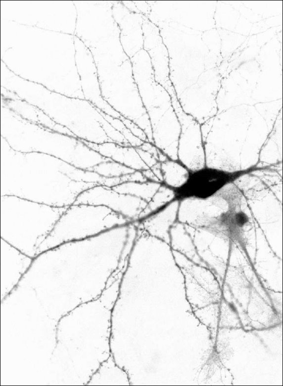
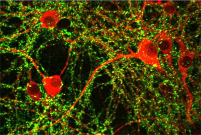
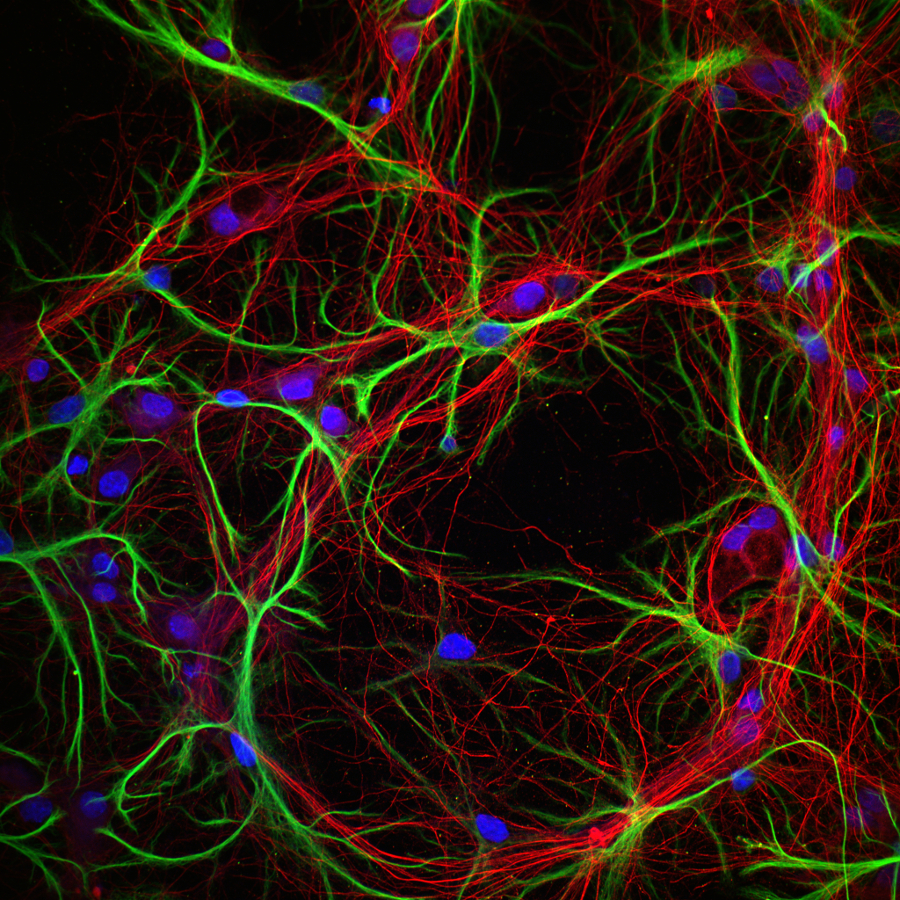
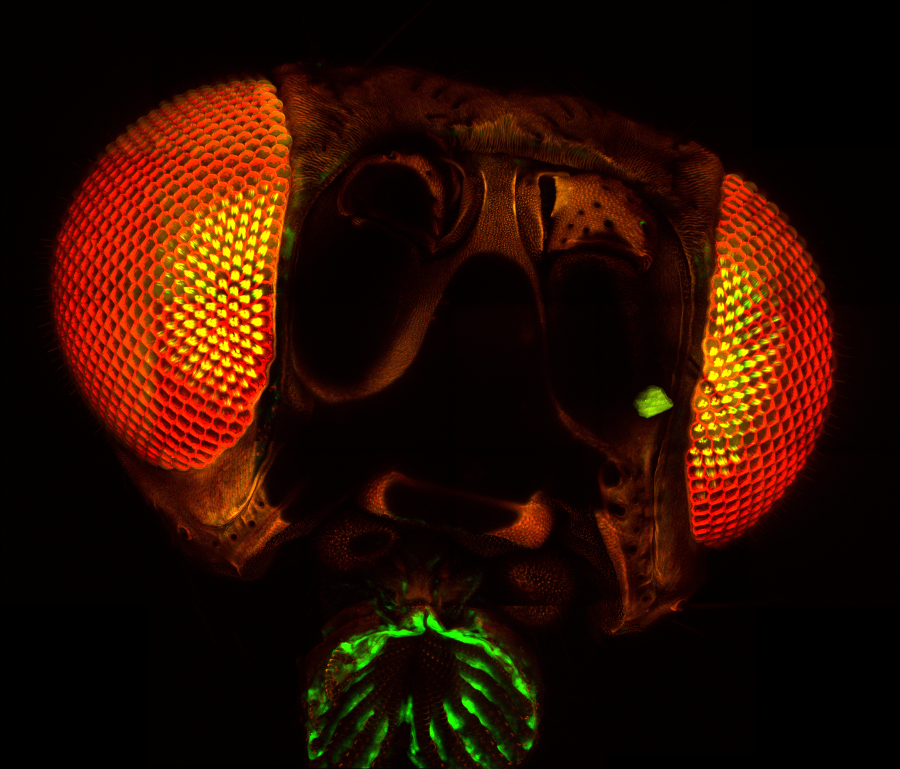
Images Obtained with Thorlabs' Confocal Systems

![]()
The full source code for ThorImage®LS is available for owners of a Bergamo®, Veneto®, or Confocal microscope. Click here to receive your copy.

ThorImage®LS Software
ThorImageLS is an open-source image acquisition program that controls Thorlabs' microscopes, as well as supplementary external hardware. From prepared-slice multiphoton Z-stacks to simultaneous in vivo photoactivation and imaging, ThorImageLS provides an integrated, modular workspace tailored to the individual needs of the scientist. Its workflow-oriented interface supports single image, Z-stacks, time series, and image streaming acquisition, visualization, and analysis. See Video 121A for a real-time view of data acquisition and analysis with ThorImageLS.
ThorImageLS is included with a Thorlabs microscope system purchase and is open source, allowing full customization of software features and performance. ThorImageLS also includes Thorlabs’ customer support and regular software updates to continually meet the imaging demands of the scientific community.
For additional details, see the full web presentation.
Advanced Software Functionality
- Multi-Column Customizable Workspace
- Image Acquisition Synced with Hardware Inputs and Timing Events
- Live Image Correction and ROI Analysis
- Independent Galvo-Galvo and Galvo-Resonant Scan Areas and Geometries
- Tiling for High-Resolution Large-Area Imaging
- Independent Primary and Secondary Z-Axis Control for Fast Deep-Tissue Scans
- Automated Image Capture with Scripts
- Compatible with ImageJ Macros
- Multi-User Settings Saved for Shared Workstations
- Individual Colors for Detection Channels Enable Simple Visual Analysis
Seamless Integration with Experiments
- Simultaneous Multi-Point Photoactivation and Imaging with Spatial Light Modulator
- Fast Z Volume Acquisition with PFM450E or Third-Party Objective Scanners
- Electrophysiology Signaling
- Wavelength Switching with Coherent Chameleon Lasers
- Pockels Cell ROI Masking
- Power Ramped with Depth to Minimize Damage and Maximize Signal-to-Noise
New Functionality: Version 4.3 (Click to Expand for More Details)
Please contact ImagingTechSupport@thorlabs.com to obtain the latest ThorImageLS version compatible with your microscope. Because ThorImageLS 4.x adds significant new features over 3.x, 2.x and 1.x versions, it may not be compatible with older microscopes. We continue to support older software versions for customers with older hardware. See the full web presentation for functionality of previous versions.
- Added Support for the Toptica iChrome CLE-50 Laser
- Added Support for 3P Imaging
- Added Support for the CS126MU, CS165MU, and CC505MU Monochrome Cameras
- Added Support for a Mini-Circuits® Switch Box
- Added Support for PMT3100R (Included in Some Bergamo Multiphoton Imaging Systems)
- Added Configurable Channel View Layout (Horizontal and Vertical)
- Added Improved Scan Path Realignment and Added Ability to Save Multiple Reference Images for Multiple Targets
- Allows for Simplified Relocation to Same Target Day to Day
- Added New Features for SLM Operation
- Added 3D Mode Toggle
- Added Z Offset
- Added Ability to Export Patterns
- Added Set Zero% and Delete All Buttons
- Added Pattern Center to Display as "0" Point
- Added SLM Control Panel Advanced Mode Enhancement
- Added New Optional Delay Between Epochs
- Added SLM Control Panel Import/Export Enhancement
- Ability to Export Table of SLM Patterns
- Added New SLM Settings
- Added to ThorSLMSettings.xml and Application Settings
- Added Ability to Offset the Z Position of Pattern Points in New 3D Mode
- Enhanced ORCA Fusion Features
- Updated Exposure Calculation for Master Pulse Mode
- Added Option to Enable Water Cooling Control
- Added Improved Performance When Switching Modalities
- Enhanced Two-Way Scanning
- Two-Way Scanning is Now Allowed Up to a Pixel Density of 4096 x 4096 When Only One Channel is Selected
- Only Selectable by Dragging the Slider Bar to the Desired Pixel Density in One-Way Before Switching to Two-Way
- Added Camera Frame Rate Control
- Added UI Control of Two Blue Mini-Circuits® Switch Boxes
- Added 3D SLM
- Added Continuous Preview and Enhanced Orthogonal Views for Z-Stacks
- Added Improved Laser Safety Control for Digital Switches When Switches Are Configured for Laser Switching
- Added Control for Stimulus Shutter Operation When Using Stimulus Capture Mode
- Added Camera Frame Rate Control
- Added a New Section to Control the Frame Rate for CMOS Cameras with this Functionality
- Added Image-Based Autofocus
- Added Ability to Find the Optimal Focus Point of the Sample Based on Image Contrast
- Added Automatic Version Update Checker
- When Connected to Internet a Version Update Check Will Occur as the Splash Screen Loads When ThorImageLS Is Started Up
- Added Signal Generator Analog Mode
- Allows Custom Control of Analog Modulation
- Added New Continuous Button for Repeated Preview
- Allows for Fast Location Sample in XZ and YZ Line Scan Mode
- Added Enhanced IPC Communication
- Added IPC Command to Load an Experiment or a Template
- Added IPC Commands to Move X, Y, Z, and Secondary Z Stages
- Added IPC Commands that Get Sent from ThorImageLS Every Time a File Is Saved During T Series Experiments
Video 121A Features of ThorImage®LS
| Supported Imaging Platforms | ||
|---|---|---|
 Veneto® Inverted Microscopes |
 Bergamo® III Multiphoton Microscopes |
 Confocal Imaging Systems |
Laser Scanning Microscopy TutorialLaser scanning microscopy (LSM) is an indispensable imaging tool in the biological sciences. In this tutorial, we will be discussing confocal fluorescence imaging, multiphoton excitation fluorescence imaging, and second and third harmonic generation imaging techniques. We will limit our discussions to point scanning of biological samples with a focus on the technology behind the imaging tools offered by Thorlabs. |
Introduction
The goal of any microscope is to generate high-contrast, high-resolution images. In much the same way that a telescope allows scientists to discern the finest details of the universe, a microscope allows us to observe biological functioning at the nanometer scale. Modern laser scanning microscopes are capable of generating multidimensional data (X, Y, Z, τ, λ), leading to a plethora of high-resolution imaging capabilities that further the understanding of underlying biological processes.
In conventional widefield microscopy (Figure 72A), high-quality images can only be obtained when using thin specimens (on the order of one to two cell layers thick). However, many applications require imaging of thick samples, where volume datasets or selection of data from within a specific focal plane is desired. Conventional widefield microscopes are unable to address these needs.
LSM, in particular confocal LSM and multiphoton LSM, allows for the visualization of thin planes from within a thick bulk sample, a technique known as optical sectioning. In confocal LSM, signals generated by the sample outside of the optical focus are physically blocked by an aperture, preventing their detection. Multiphoton LSM, as we will discuss later, does not generate any appreciable signal outside of the focal plane. By combining optical sectioning with incremented changes in focus (Figure 72B), laser scanning microscopy techniques can recreate 3D representations of thick specimen.
|
Figure 72A Widefield Epi-Fluorescence
|
|
Figure 72B Optical Sections (Visualization of Thin Planes within a Bulk Sample)
Signal generated by the sample is shown in green. Optical sections are formed by discretely measuring the signal generated within a specific focal plane. In confocal LSM, out-of-focus light is rejected through the use of a pinhole aperture, thereby leading to higher resolution. In multiphoton LSM, signal is only generated in the focal volume. Signal collected at each optical section can be reconstructed to create a 3D image. |

Contrast Mechanisms in LSM
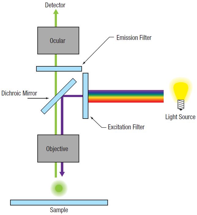
Biological samples typically do not have very good contrast, which leads to difficulty in observing the boundaries between adjacent structures. A common method for improving contrast in laser scanning microscopes is through the use of fluorescence.
In fluorescence, a light-emitting molecule is used to distinguish the constituent of interest from the background or neighboring structure. This molecule can already exist within the specimen (endogenous or auto-fluorescence), be applied externally and attached to the constituent (chemically or through antibody binding), or transfected (fluorescent proteins) into the cell.
In order for the molecule to emit light (fluoresce) it must first absorb light (a photon) with the appropriate amount of energy to promote the molecule from the ground state to the excited state, as seen in Figure 72C (a). Light is emitted when the molecule returns back down to the ground state. The amount of fluorescence is proportional to the intensity (I) of the incident laser, and so confocal LSM is often referred to as a linear imaging technique. Natural losses within this relaxation process require that the emitted photon have lower energy—that is, a longer wavelength—than the absorbed photon.
Multiphoton excitation [Figure 72C (b)] of the molecule occurs when two (or more) photons, whose sum energy satisfies the transition energy, arrive simultaneously. Consequently, the two arriving photons will be of lower energy than the emitted fluorescence photon.
There are also multiphoton contrast mechanisms, such as harmonic generation and sum frequency generation, that use non-absorptive processes. Under conditions in which harmonic generation is allowed, the incident photons are simultaneously annihilated and a new photon of the summed energy is created, as illustrated in Figure 72C (c).
Further constituent discrimination can be obtained by observing the physical order of the harmonic generation. In the case of second harmonic generation (SHG), signal is only generated in constituents that are highly ordered and lacking inversion symmetry. Third harmonic generation (THG) is observed at boundary interfaces where there is a refractive index change. Two-photon excitation and SHG are nonlinear processes and the signal generated is dependent on the square of the intensity (I2).
The nonlinear nature of signal generation in multiphoton microscopy means that high photon densities are required to observe SHG and THG. In order to accomplish this while maintaining relatively low average power on the sample, mode-locked femtosecond pulsed lasers, particularly Ti:Sapphire lasers, have become the standard.
Another consideration to be made in nonlinear microscopy is the excitation wavelength for a particular fluorophore. One might think that the ideal excitation wavelength is twice that of the one-photon absorption peak. However, for most fluorophores, the excited state selection rules are different for one- and two-photon absorption.
This leads to two-photon absorption spectra that are quite different from their one-photon counterparts. Two-photon absorption spectra are often significantly broader (can be >100 nm) and do not follow smooth semi-Gaussian curves. The broad two-photon absorption spectrum of many fluorophores facilitates excitation of several fluorescent molecules with a single laser, allowing the observation of several constituents of interest simultaneously.
All of the fluorophores being excited do not have to have the same excitation peak, but should overlap each other and have a common excitation range. Multiple fluorophore excitation is typically accomplished by choosing a compromising wavelength that excites all fluorophores with acceptable levels of efficiency.
|
Figure 72C Signal Generation in Laser Scanning Microscopy
Absorptive Process (a, b): The absorption of one or more excitation photons (λEX) promotes the molecule from the ground state (S0) to the excited state (S1). Fluorescence (λEM) is emitted when the molecule returns to the ground state. Non-Absorptive Process (c): The excitation photons (λEX) simultaneously convert into a single photon (λSHG,THG) of the sum energy and half (for SHG) or one-third (for THG) the wavelength.
|


Image Formation
In a point-scanning LSM, the single-plane image is created by a point illumination source imaged to a diffraction-limited spot at the sample, which is then imaged to a point detector. Two-dimensional en face images are created by scanning the diffraction-limited spot across the specimen, point by point, to form a line, then line by line in a raster fashion.
The illuminated volume emits a signal which is imaged to a single-element detector. The most common single-element detector used is a photomultiplier tube (PMT), although in certain cases, avalanche photodiodes (APDs) can be used. CCD cameras are not typically used in point-scanning microscopes, though are the detector of choice in multifocal (i.e. spinning disk confocal) applications.
The signal from the detector is then passed to a computer which constructs a two-dimensional image as an array of intensities for each spot scanned across the sample. Because no true image is formed, LSM is referred to as a digital imaging technique. A clear advantage of single-point scanning and single-point detection is that the displayed image resolution, optical resolution, and scan field can be set to match a particular experimental requirement and are not predefined by the imaging optics of the system.
| Figure 72D Confocal Optical Path
|
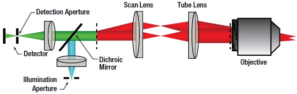
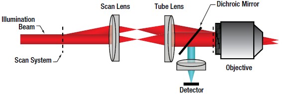
Confocal LSM
In confocal LSM, point illumination, typically from a single mode, optical-fiber-coupled CW laser, is the critical feature that allows optical sectioning. The light emitted from the core of the single mode optical fiber is collimated and used as the illumination beam for scanning. The scan system is then imaged to the back aperture of the objective lens which focuses the scanned beam to a diffraction-limited spot on the sample. The signal generated by the focused illumination beam is collected back through the objective and passed through the scan system.
After the scan system, the signal is separated from the illumination beam by a dichroic mirror and brought to a focus. The confocal pinhole is located at this focus. In this configuration, signals that are generated above or below the focal plane are blocked from passing through the pinhole, creating the optically sectioned image (Figure 72B). The detector is placed after the confocal pinhole, as illustrated in Figure 72D. It can be inferred that the size of the pinhole has direct consequences on the imaging capabilities (particularly, contrast, resolution and optical section thickness) of the confocal microscope.
The lateral resolution of a confocal microscope is determined by the ability of the system to create a diffraction-limited spot at the sample. Forming a diffraction-limited spot depends on the quality of the laser beam as well as that of the scan optics and objective lens.
The beam quality is typically ensured by using a single mode optical fiber to deliver the excitation laser light as a Gaussian point source, which is then collimated and focused into a diffraction-limited beam. In an aberration-free imaging system, obtained by using the highest quality optical elements, the size of this focus spot, assuming uniform illumination, is a function of excitation wavelength (λEX) and numerical aperture (NA) of the objective lens, as seen in Equation 1.
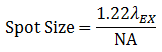
Equation 1 Spot Size
In actuality, the beam isn't focused to a true point, but rather to a bullseye-like shape. The spot size is the distance between the zeros of the Airy disk (diameter across the middle of the first ring around the center of the bullseye) and is termed one Airy Unit (AU). This will become important again later when we discuss pinhole sizes.
The lateral resolution of the imaging system is defined as the minimum distance between two points for them to be observed as two distinct entities. In confocal (and multiphoton) LSM, it is common and experimentally convenient to define the lateral resolution according to the full width at half maximum (FWHM) of the individual points that are observed.
Using the FWHM definition, in confocal LSM, the lateral resolution (Rlateral,confocal) is:
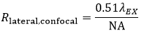
Equation 2 Lateral Resolution, Confocal LSM
and the axial resolution (Raxial,confocal) is:
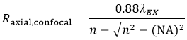
Equation 3 Axial Resolution, Confocal LSM
where n is the refractive index of the immersion medium.
It is interesting to note that in a confocal microscope, the lateral resolution is solely determined by the excitation wavelength. This is in contrast to widefield microscopy, where lateral resolution is determined only by emission wavelength.
To determine the appropriate size of the confocal pinhole, we multiply the excitation spot size by the total magnification of the microscope:

Equation 4 Pinhole Diameter
As an example, the appropriate size pinhole for a 60X objective with NA = 1.0 for λEX = 488 nm (Mscan head = 1.07 for the Thorlabs Confocal Scan Head) would be 38.2 μm and is termed a pinhole of 1 AU diameter. If we used the same objective parameters but changed the magnification to 40X, the appropriate pinhole size would be 25.5 μm and would also be termed a pinhole of 1 AU diameter. Therefore, defining a pinhole diameter in terms of AU is a means of normalizing pinhole diameter, even though one would have to change the pinhole selection for the two different objectives.
Theoretically, the total resolution of a confocal microscope is a function of the excitation illumination spot size and the detection pinhole size. This means that the resolution of the optical system can be improved by reducing the size of the pinhole. Practically speaking, as we restrict the pinhole diameter, we improve resolution and confocality, but we also reduce the amount of signal reaching the detector. A pinhole of 1 AU is a good balance between signal strength, resolution, and confocality.
| Figure 72E Multiphoton Optical Path
|
Multiphoton LSM
In multiphoton LSM, a short pulsed free-space laser supplies the collimated illumination beam that passes through the scanning system and is focused by the objective. The very low probability of a multiphoton absorption event occurring, due to the I2 dependence of the signal on incident power, ensures signal is confined to the focal plane of the objective lens. Therefore, very little signal is generated from the regions above and below the focal plane. This effective elimination of out-of-focus signal provides inherent optical sectioning capabilities (Figure 72B) without the need for a confocal pinhole. As a result of this configuration, the collected signal does not have to go back through the scanning system, allowing the detector to be placed as close to the objective as possible to maximize collection efficiency, as illustrated in Figure 72E. A detector that collects signal before it travels back through the scan system is referred to as a non-descanned detector.
Again using the FWHM defintion, in multiphoton LSM, the lateral resolution (Rlateral,multiphoton) is:
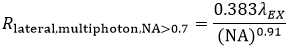
Equation 5 Lateral Resolution, Multiphoton LSM
and the axial resolution (Raxial,multiphoton) is:
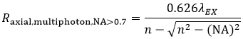
Equation 6 Axial Resolution, Multiphoton LSM
These equations assume an objective NA > 0.7, which is true of virtually all multiphoton objectives.
The longer wavelength used for multiphoton excitation would lead one to believe (from Equation 5) that the resolution in multiphoton LSM, compared to confocal LSM, would be reduced roughly by a factor of two. For an ideal point object (i.e. a sub-resolution size fluorescent bead) the I2 signal dependence reduces the effective focal volume, more than offsetting the 2X increase in the focused illumination spot size.
We should note that the lateral and axial resolutions display a dependence on intensity. As laser power is increased, there is a corresponding increase in the probability of signal being generated within the diffraction-limited focal volume. In practice, the lateral resolution in a multiphoton microscope is limited by how tightly the illumination beam can be focused and is well approximated by Equation 5 at moderate intensities. Axial resolution will continue to degrade as excitation power is increased.
Image Display
Although we are not directly rendering an image, it is still important to consider the size of the image field, the number of pixels in which we are displaying our image (capture resolution) on the screen, and the lateral resolution of the imaging system. We use the lateral resolution because we are rendering an en face image. In order to faithfully display the finest features the optical system is capable of resolving, we must appropriately match resolution (capture and lateral) with the scan field. Our capture resolution must, therefore, appropriately sample the optical resolution.
In LSM, we typically rely on Nyquist sampling rules, which state that the pixel size should be the lateral resolution divided by 2.3. This means that if we take our 60X objective from earlier, the lateral resolution is 249 nm (Equation 2) and the pixel size in the displayed image should be 108 nm. Therefore, for a 1024 x 1024 pixel capture resolution, the scan field on the specimen would be ~111 μm x 111 μm. It should be noted that the 40X objective from our previous example would yield the exact same scan field (both objectives have the same NA) in the sample. The only difference between the two images is the angle at which we tilt our scanners to acquire the image.
It may not always be necessary to render images with such high resolution. We can always make the trade-off of image resolution, scan field, and capture resolution to create a balance of signal, sample longevity, and resolution in our images.
Considerations in Live Cell Imaging
One of LSM's greatest attributes is its ability to image living cells and tissues. Unfortunately, some of the by-products of fluorescence can be cytotoxic. As such, there is a delicate balancing act between generating high-quality images and keeping cells alive.
One important consideration is fluorophore saturation. Saturation occurs when increasing the laser power does not provide the expected concurrent increase in the fluorescence signal. This can occur when as few as 10% of the fluorophores are in the excited state.
The reason behind saturation is the amount of time a fluorophore requires to relax back down to the ground state once excited. While the fluorescence pathways are relatively fast (hundreds of ps to a few ns), this represents only one relaxation mechanism. Triplet state conversion and nonradiative decay require significantly longer relaxation times. Furthermore, re-exciting a fluorophore before it has relaxed back down to the ground state can lead to irreversible bleaching of the fluorophore. Cells have their own intrinsic mechanisms for dealing with the cytotoxicity associated with fluorescence, so long as excitation occurs slowly.
One method to reduce photobleaching and the associated cytotoxicity is through fast scanning. While reducing the amount of time the laser spends on a single point in the image will proportionally decrease the amount of detected signal, it also reduces some of the bleaching mechanisms by allowing the fluorophore to completely relax back to the ground state before the laser is scanned back to that point. If the utmost in speed is not a critical issue, one can average several lines or complete frames and build up the signal lost from the shorter integration time.
The longer excitation wavelength and non-descanned detection ability of multiphoton LSM give the ability to image deeper within biological tissues. Longer wavelengths are less susceptible to scattering by the sample because of the inverse fourth power dependence (I-4) of scattering on wavelength. Typical penetration depths for multiphoton LSM are 250 - 500 μm, although imaging as deep as 1 mm has been reported in the literature, compared to ~100 μm for confocal LSM.
Thorlabs recognizes that each imaging application has unique requirements.
If you have any feedback, questions, or need a quotation, please contact ImagingSales@thorlabs.com or call (703) 651-1700.

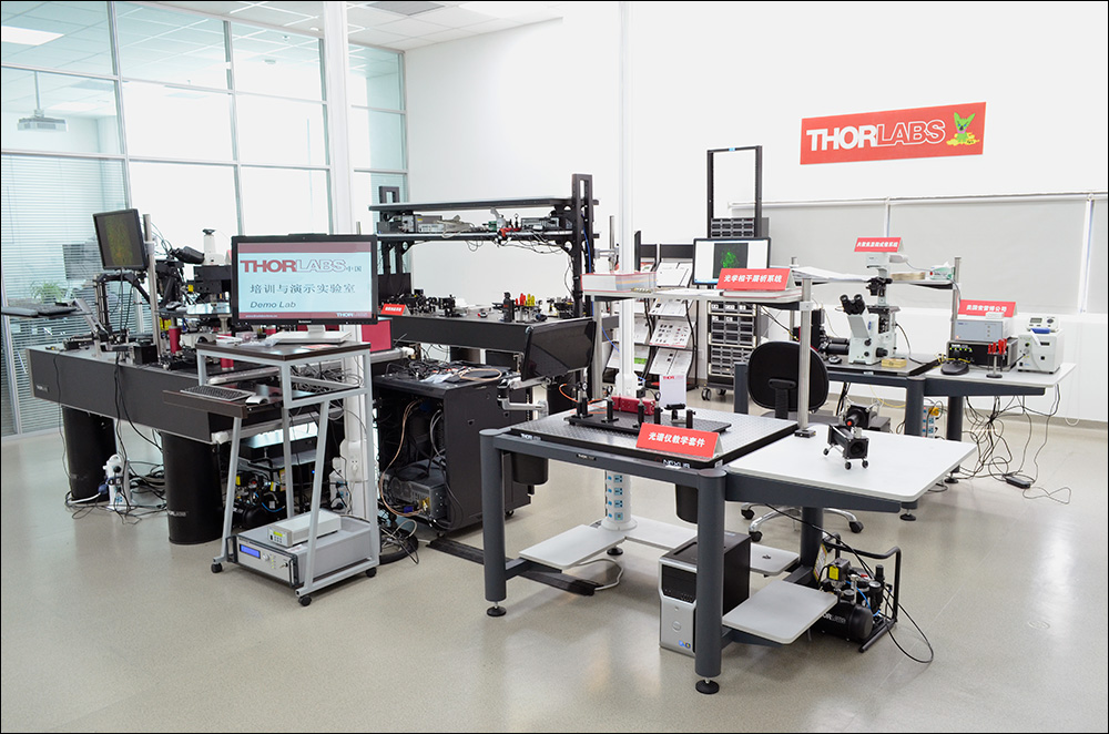
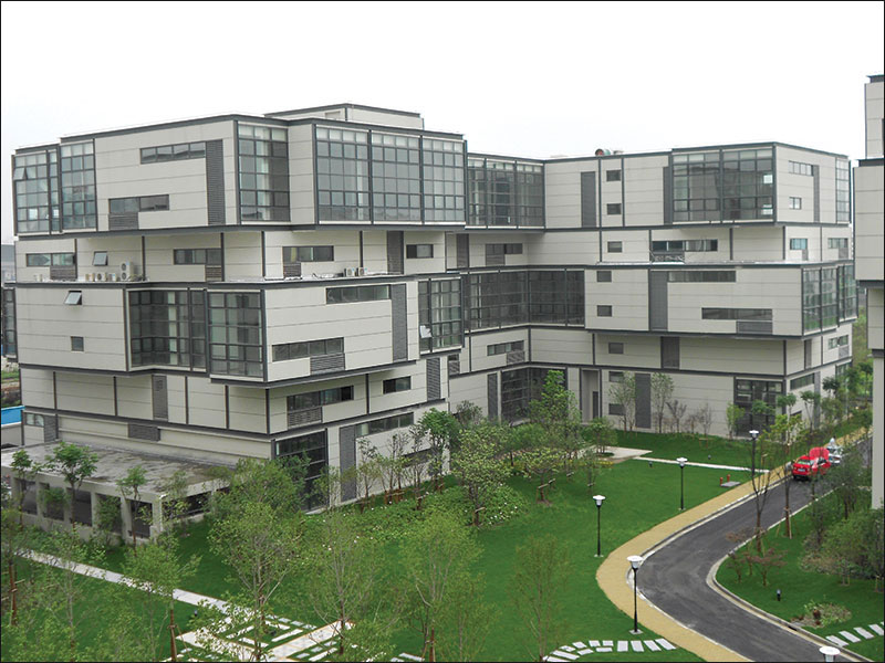
Click to Enlarge
Figure 39A China Demo Room
Try Our Microscopes In Person or Virtually
Thorlabs' sales engineers and field service staff are based out of nine offices across four continents. We look forward to helping you determine the best imaging system to meet your specific experimental needs. Our customers are attempting to solve biology's most important problems; these endeavors require matching systems that drive industry standards for ease of use, reliability, and raw capability.
Thorlabs' worldwide network allows us to operate demo rooms in a number of locations where you can see our systems in action. We welcome the opportunity to work with you in person or virtually. A demo can be scheduled at any of our showrooms or virtually by contacting ImagingSales@thorlabs.com.
Customer Support Sites
(Click Each Location for More Details)
Newton, New Jersey, USA

Thorlabs Headquarters
43 Sparta Avenue
Newton, NJ 07860
Customer Support
- Phone: (973) 300-3000
- E-mail: techsupport@thorlabs.com
Ely, United Kingdom

Thorlabs Ltd.
1 Saint Thomas Place, Ely
Ely CB7 4EX
Customer Support
- Phone: +44 (0)1353-654440
- E-mail: techsupport.uk@thorlabs.com
Bergkirchen, Germany
Thorlabs GmbH
Münchner Weg 1
85232 Bergkirchen
Customer Support
- Phone: +49 (0) 8131-5956-0
- E-mail: europe@thorlabs.com
Puteaux, France

Thorlabs SAS
76 Route de la Demi Lune
92800 Puteaux
Customer Support
- Phone: +33 (0) 970 440 844
- E-mail: techsupport.fr@thorlabs.com
São Carlos, SP, Brazil
Thorlabs Vendas de Fotônicos Ltda.
Rua Rosalino Bellini, 175
Jardim Santa Paula
São Carlos, SP, 13564-050
Customer Support
- Phone: +55 (21) 2018 6490
- E-mail: brasil@thorlabs.com
Demo Rooms and Customer Support Sites
(Click Each Location for More Details)
Sterling, Virginia, USA

Thorlabs Imaging Systems HQ
108 Powers Court
Sterling, VA 20166
Customer Support
- Phone: (703) 651-1700
- E-mail: ImagingTechSupport@thorlabs.com
Demo Rooms
- Bergamo® Series Multiphoton Microscopes
- Veneto® Inverted Microscopes
- Upright Confocal Microscopy Systems
- Cerna Birefringence Imaging Microscopes
- Multiphoton Mesoscope
- OCT Systems: Telesto® and Ganymede®
Lübeck, Germany
Thorlabs GmbH
Maria-Goeppert-Straße 9
23562 Lübeck
Customer Support
- Phone: +49 (0) 8131-5956-40840
- Email: oct@thorlabs.com
Demo Rooms
- Ganymede® Series SD-OCT Systems
- Telesto® Series SD-OCT Systems
- Telesto® Series PS-OCT Systems
- Atria® Series SS-OCT Systems
- Vega™ Series SS-OCT Systems
Nerima-ku, Tokyo, Japan

Thorlabs Japan, Inc.
3-6-3 Kitamachi
Nerima-ku, Tokyo 179-0081
Customer Support
- Phone: +81-3-6915-7701
- Email: sales@thorlabs.jp
Demo Rooms
Shanghai, China
Thorlabs China
Room A101, No. 100, Lane 2891, South Qilianshan Road
Shanghai 200331
Customer Support
- Phone: +86 (0)21-60561122
- Email: techsupport-cn@thorlabs.com
Demo Rooms
- Bergamo® Series Multiphoton Microscopes
- Cerna Birefringence Imaging Microscopes
- OCT Systems: Telesto® and Ganymede®
Selected Confocal Microscopy Publications
2025
Romanova, D. Y., Povernov, A. A., Nikitin, M. A., Borman, S. I., Frank, Y. A., & Moroz, L. L. (2025). Long-term dynamics of placozoan culture: emerging models for population and space biology. Frontiers in Cell and Developmental Biology, 12, 1514553.
2024
Lin, Y., Mos, P., Ardelean, A., Bruschini, C., & Charbon, E. (2024). Coupling a recurrent neural network to SPAD TCSPC systems for real-time fluorescence lifetime imaging. Scientific Reports, 14(1), 3286.
Gutjahr, R., Kéver, L., Jonsson, T., Talamantes Ontiveros, D., Chagnaud, B. P., & Herrel, A. (2024). Gekko gecko as a model organism for understanding aspects of laryngeal vocal evolution. Journal of Experimental Biology, 227(15).
Smirnov, I. V., Osipova, A. A., Smirnova, M. P., Borodinova, A. A., Volgushev, M. A., & Malyshev, A. Y. (2024). Plasticity of Response Properties of Mouse Visual Cortex Neurons Induced by Optogenetic Tetanization In Vivo. Current Issues in Molecular Biology, 46(4), 3294-3312.
2023
Egorova, P. A., Marinina, K. S., & Bezprozvanny, I. B. (2023). Chronic suppression of STIM1-mediated calcium signaling in Purkinje cells rescues the cerebellar pathology in spinocerebellar ataxia type 2. Biochimica et Biophysica Acta (BBA)-Molecular Cell Research, 1870(5), 119466.
2022
Pchitskaya, E., Rakovskaya, A., Chigray, M., & Bezprozvanny, I. (2022). Cytoskeleton protein EB3 contributes to dendritic spines enlargement and enhances their resilience to toxic effects of beta-amyloid. International journal of molecular sciences, 23(4), 2274.
Simonova, N. A., Volgushev, M. A., & Malyshev, A. Y. (2022). Enhanced non-associative long-term potentiation in immature granule cells in the dentate gyrus of adult rats. Frontiers in Synaptic Neuroscience, 14, 889947.
Zernov, N., Ghamaryan, V., Makichyan, A., Melenteva, D., Hunanyan, L., & Popugaeva, E. (2022). Piperazine derivative stabilizes actin filaments in primary fibroblasts and binds G-actin in silico. Current Issues in Molecular Biology, 44(11), 5191-5208.
Zernov, N., Bezprozvanny, I., & Popugaeva, E. (2022). CaMKIIβ knockdown decreases store-operated calcium entry in hippocampal dendritic spines. IBRO Neuroscience Reports, 12, 90-97.
2021
Kraskovskaya, N. A., Erofeev, A. I., Grishina, E. D., Pushkareva, S. A., Gerasimov, E. I., Vlasova, O. L., & Bezprozvanny, I. B. (2021). Development of hippocampus-associated cognitive dysfunction in Huntington’s disease mouse model. Journal of Evolutionary Biochemistry and Physiology, 57, 1449-1460.
2020
Caccavano, A., Bozzelli, P. L., Forcelli, P. A., Pak, D. T., Wu, J. Y., Conant, K., & Vicini, S. (2020). Inhibitory parvalbumin basket cell activity is selectively reduced during hippocampal sharp wave ripples in a mouse model of familial Alzheimer's disease. Journal of Neuroscience, 40(26), 5116-5136.
Dark, C., Williams, C., Bellgrove, M. A., Hawi, Z., & Bryson-Richardson, R. J. (2020). Functional validation of CHMP7 as an ADHD risk gene. Translational psychiatry, 10(1), 385.
2016
Lewin, A. E., Vicini, S., Richardson, J., Dretchen, K. L., Gillis, R. A., & Sahibzada, N. (2016). Optogenetic and pharmacological evidence that somatostatin-GABA neurons are important regulators of parasympathetic outflow to the stomach. The Journal of Physiology, 594(10), 2661-2679.
Zuo, S., Hughes, M., & Yang, G. Z. (2016). Novel balloon surface scanning device for intraoperative breast endomicroscopy. Annals of biomedical engineering, 44, 2313-2326.
2015
Dechen, K., Richards, C. D., Lye, J. C., Hwang, J. E., & Burke, R. (2015). Compartmentalized zinc deficiency and toxicities caused by ZnT and Zip gene over expression result in specific phenotypes in Drosophila. The International Journal of Biochemistry & Cell Biology, 60, 23-33.
Jia, Y., Zhang, S., Miao, L., Wang, J., Jin, Z., Gu, B., ... & Li, Z. (2015). Activation of platelet protease-activated receptor-1 induces epithelial-mesenchymal transition and chemotaxis of colon cancer cell line SW620 Corrigendum in/or/35/2/1222. Oncology reports, 33(6), 2681-2688.
Lu, W., Tang, Y., Zhang, Z., Zhang, X., Yao, Y., Fu, C., ... & Ma, G. (2015). Inhibiting the mobilization of Ly6Chigh monocytes after acute myocardial infarction enhances the efficiency of mesenchymal stromal cell transplantation and curbs myocardial remodeling. American journal of translational research, 7(3), 587.
Lu, W., Xie, Z., Tang, Y., Bai, L., Yao, Y., Fu, C., & Ma, G. (2015). Photoluminescent mesoporous silicon nanoparticles with siCCR2 improve the effects of mesenchymal stromal cell transplantation after acute myocardial infarction. Theranostics, 5(10), 1068.
2014
Brown, C. M., Melcher, J. T., & Stranick, S. J. (2014). Scan Linearization for Resonant Optomechanical Systems. In Imaging Systems and Applications (pp. IM1C-3). Optica Publishing Group.
Partridge, J. G., Lewin, A. E., Yasko, J. R., & Vicini, S. (2014). Contrasting actions of group I metabotropic glutamate receptors in distinct mouse striatal neurones. The Journal of physiology, 592(13), 2721-2733.
Qin, X., Qiu, C., & Zhao, L. (2014). Maslinic acid protects vascular smooth muscle cells from oxidative stress through Akt/Nrf2/HO-1 pathway. Molecular and cellular biochemistry, 390, 61-67.
Liu, J., Wu, N., Ma, L., Liu, M., Liu, G., Zhang, Y., & Lin, X. (2014). Oleanolic acid suppresses aerobic glycolysis in cancer cells by switching pyruvate kinase type M isoforms. PloS one, 9(3), e91606.
2013
Hao, X., Kuang, C., Gu, Z., Li, S., Li, Y., & Liu, X. (2013). Contrast reversal confocal microscopy. Optics Communications, 298, 272-275.
Lalchandani, R. R., van der Goes, M. S., Partridge, J. G., & Vicini, S. (2013). Dopamine D2 receptors regulate collateral inhibition between striatal medium spiny neurons. Journal of Neuroscience, 33(35), 14075-14086.
| Posted Comments: | |
| No Comments Posted |