 Products Home
Compact Balanced Amplified Photodetectors
- 400 MHz or 2.5 GHz Balanced Receivers with Compact Footprints
- Noise Cancellation by Subtraction of 2 Input Signals
- >20 dB Common Mode Rejection Ratio
- Volume Pricing Available for OEMs
- Customization Options Available
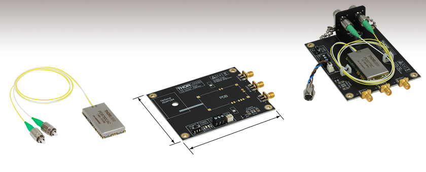
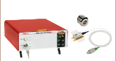
PDB780CAC
2.5 GHz Balanced Amplified Detector with FC/APC Connectors
100.0 mm
(3.93")
80.0 mm
(3.15")
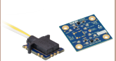
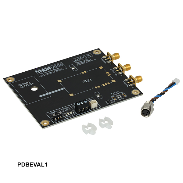
PDBEVAL1
Evaluation Board for the PDB77xC and PDB78xCAC Detectors
Application Idea
The PDB770C 400 MHz Balanced Detector soldered to the PDBEVAL1 Evaluation Board. An ADAFCB4 Fiber Bracket (not included) is used to hold the detector's FC/APC connectors.


Please Wait
| Balanced Detector Selection Guide |
|---|
| Balanced Detectors with Fast Monitor Output |
| Large-Area Balanced Amplified Detectors |
| Suitable for OCT |
| Compact Balanced Amplified Detectors |
| Compact Balanced Detectors |
| OCT Balanced Detectors with Fast Monitor Output |
| Auto-Balanced Detector with Avalanche Photodiodes |
Applications
- OEM Balanced, Amplified Detection
- LIDAR Systems
- OCT Systems
- Optical Frequency Domain Reflectometry
Features
- InGaAs Balanced Photodetectors with 400 MHz or 2.5 GHz Bandwidth
- Wavelength Range:
- PDB771C and PDB781CAC: HI1060 Fiber, 980 - 1625 nm
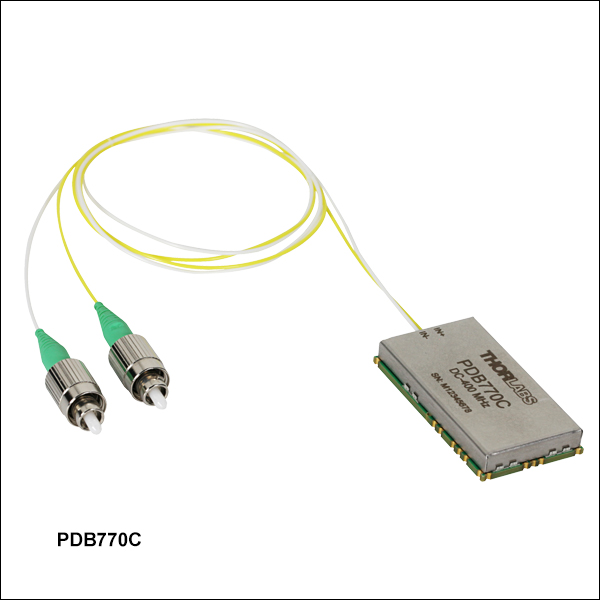
- PDB770C and PDB780CAC: SMF-28 Ultra, 1260 - 1625 nm
- Surface Mount Component (Solders Directly to PCB)
- Small Footprint: 45.0 mm x 25.0 mm x 7.0 mm
- Evaluation Board with SMA Outputs Available
- FC/APC-Terminated Versions Available from Stock
- Bandwidth, Gain, and Connector Type Customization Options Available; Contact Tech Support for Details
Thorlabs' Compact Balanced Amplified Photodetectors are high-speed InGaAs detectors with a small footprint specifically designed for OEM applications. With a common mode rejection ratio (CMRR) of >20 dB, these detectors are ideal for techniques requiring high sensitivity, such as LIDAR, OCT, and optical frequency domain reflectometry. Detectors operate over the 980 nm to 1625 nm or 1260 nm to 1625 nm wavelength ranges and are available with bandwidths of 400 MHz or 2.5 GHz. Detailed performance specifications can be found by clicking on the blue info icons (![]() ) in Tables G1.1 and G2.1.
) in Tables G1.1 and G2.1.
Each detector consists of two well-matched photodiodes and an ultra-low-noise, ultra-low-distortion, high-speed transimpedance amplifier. To act as a balanced receiver, the compact detector subtracts the two optical input signals from each other, which results in the cancellation of common mode noise. This allows small changes in the signal path to be extracted from the interfering noise floor. Each unit also includes two monitor outputs for measuring the individual optical input power levels, as well as low-frequency modulated signals up to 150 kHz. Please see the Operation tab for more details.
Featuring an HI1060 fiber, the PDB771C and PDB781CAC detectors operate over the 980 nm to 1625 nm wavelength range and are optimized for use at 1060 nm. The PDB770C and PDB780CAC compact balanced detectors include an SMF-28 Ultra fiber and are suitable for use in the 1260 nm to 1625 nm wavelength range, with optimized performance at 1310 nm. Each detector module has two fiber leads with Ø900 µm buffer jackets, where one photodiode has a yellow buffer and the second has white for easy identification. The two fibers are 50 cm long and matched in length to <1 mm (with connectors), which ensures the equal optical path lengths needed for common mode noise suppression. Detectors with narrow key FC/APC connectors are available from stock; units with other connector types are available by contacting Tech Support.
Mounting and External Connection
We also offer an evaluation board for mounting and accessing the output signals from these balanced amplified detectors. This board features a pre-defined footprint for soldering the detector in place, SMA connectors for signal output, and connections for a power supply. Included with each PDBEVAL1 board is an RKMF3 connector cable for connecting the Thorlabs LDS12B ±12 VDC Power Supply (not included). Alternatively, each detector's surface mount package can be soldered to a custom PCB; please see the Pin Diagrams tab for more information about the external pin connections. Please refer to the detector's spec sheet for complete instructions on connecting and operating each device.
Please note that the components inside these modules are ESD sensitive. Take all appropriate precautions to discharge personnel and equipment before making any electrical connections to the unit. All soldering must be done by hand; a reflow oven will damage the device.
Packaged Balanced Amplified Photodetectors
Thorlabs also offers balanced amplified photodetectors with fast monitor outputs in shielded aluminum enclosures for out-of-the-box detection solutions. These detectors are available with bandwidths up to 2.5 GHz and have a >20 dB CMRR.
Click to Enlarge
External pin Connections for the PDB780CAC Balanced Detector. The pin connections are the same for all PDB781CAC detectors.
Click to Enlarge
External pin Connections for the PDB770C Balanced Detector. The pin connections are the same for the PDB771C detectors.
| Pin | Description | Pin | Description |
|---|---|---|---|
| 1 | Ground | 10 | Ground |
| 2 | Ground | 11 | Ground |
| 3 | Ground | 12 | Ground |
| 4 | Ground | 13 | Power Supply (-12 V) |
| 5 | Output (Monitor +) | 14 | Power Supply (+12 V) |
| 6 | Ground | 15 | Ground |
| 7 | Ground | 16 | Output (Monitor -) |
| 8 | Ground | 17 | Ground |
| 9 | RF Output | 18 | Ground |
| Pin | Description | Pin | Description |
|---|---|---|---|
| 1 | Ground | 10 | Ground |
| 2 | Ground | 11 | Ground |
| 3 | Ground | 12 | Ground |
| 4 | Ground | 13 | Power Supply (-9 V to -12 V) |
| 5 | Output (Monitor +) | 14 | Power Supply (+9 V to +12 V) |
| 6 | Ground | 15 | Ground |
| 7 | Ground | 16 | Output (Monitor -) |
| 8 | Ground | 17 | Ground |
| 9 | RF Output | 18 | Ground |
Operation
Thorlabs' Balanced Amplified Photodetectors consists of two well-matched photodiodes and an ultra-low-noise, high-speed transimpedance amplifier (TIA) that generates an output voltage (RF OUTPUT) proportional to the difference between the photocurrents in the two photodiodes (i.e., the two optical input signals). Additionally, each unit has two 150 kHz monitor outputs (MONITOR+ and MONITOR-) to observe the optical input power levels at each photodiode separately. These outputs are low-frequency outputs and cannot be used to measure an RF modulation on the signal.
Click to Enlarge
Figure 4.2 Dimensions for the bottom view of the PDB770C Balanced Amplified Detector. The dimensions are the same for all PDB77xC and PDB78xCAC detectors.
Click to Enlarge
Figure 4.1 Dimensions for the top view of the PDB770C Balanced Amplified Detector. The dimensions are the same for all PDB77xC and PDB78xCAC detectors.
| Posted Comments: | |
Mahesh Lunavath
(posted 2024-01-31 22:02:56.963) Hi,
We have procured (10 no's) PDB780CAC BPDs (1MHz-2.5GHz) along with its evaluation board. Recently while testing these detectors (without any input optical signal) we have observed, it is generating signals around 20.5kHz and its harmonics. We have verified this phenomenon in ESA and Digital Oscilloscope too. This signal appears after we switch on the power supply. We have tested with LDSB12 and other DC power supplies but this 20kHz signals is always present.
I am wondering what could be the source of this spurious signal ? Kindly let us know. I can share the RF output screenshots and any more information required.
Thankyou. dpossin
(posted 2024-02-06 04:51:17.0) Dear Mahesh,
Thank you for your inquiry. I will reach out to you directly in order to discuss that with you. AARON TRAXINGER
(posted 2022-02-15 11:20:58.61) I am wondering if you have a mechanical drawing of the recommended PCB pad layout? hkarpenko
(posted 2022-02-22 11:12:58.0) Hi Aaron,
thank you for contacting Thorlabs.
The drawing of the PCB pad layout can be found in the manual of the PDB770C on page 4 with a top view and a bottom view, which can be donwloaded from our website.
I reach out to you directly and attach the document. user
(posted 2021-01-18 09:11:18.787) Is the PDB780CAC (2.5 [GHz]) available in packaged form, similar to the PDB480CAC (1.6 [GHz])? It is for an application at 1550 [nm]. MKiess
(posted 2021-01-19 08:16:02.0) Thank you for contacting Thorlabs. Unfortunately, this detector, built into such a housing is not available as a standard article.
We might be able to manufacture a custom product according to your wishes or we can find a suitable alternative together. If you wish to do so, please contact our technical support at the e-mail address, europe@thorlabs.com. user
(posted 2020-08-29 00:05:36.357) Hi, I want to know the damage threshold of PDB770C photo-detector under a pulsed 300fs laser? What is the rough max power or single pulse energy I can apply to this detector? Thanks a lot! dpossin
(posted 2020-09-01 07:04:02.0) Dear Customer,
Thank you for your feedback! If the PDB770C is suitable for the laser depends on the repetition rate and pulse length. The saturation limit is 440 µW @ 1300nm. I am reaching out to you in order to check with you your laser properties. |

 Zoom
Zoom| Table G1.1 Key Specsa,b | |||||||||
|---|---|---|---|---|---|---|---|---|---|
| Item # | Full Specs |
Wavelength Range | Typ. Max Responsivity | Bandwidth (3 dB) |
CMRRc | Transimpedance Gain |
Monitor Output Bandwidth (3 dB) | Fiber Connector |
Fiber Type |
| PDB771C | 980 - 1625 nm | 0.70 A/W at 1050 nm |
DC - 400 MHz | >25 dB | 10 x 103 V/A | DC - 150 kHz | FC/APCd | HI1060 | |
| PDB770C | 1260 - 1625 nm | 0.85 A/W at 1310 nm |
SMF-28 Ultra |
||||||
- For complete specifications, please click the blue info icons (
 ) above.
 - All specifications are valid at 23 ± 5 °C and 45 ± 15% rel. humidity (non-condensing).
- Common Mode Rejection Ratio
- 2.0 mm Narrow Key FC/APC Connector

 Zoom
Zoom| Table G2.1 Key Specsa,b | |||||||||
|---|---|---|---|---|---|---|---|---|---|
| Item # | Full Specs |
Wavelength Range | Typ. Max Responsivity | Bandwidth (3 dB) |
CMRRc | Transimpedance Gain |
Monitor Output Bandwidth (3 dB) | Fiber Connector |
Fiber Type |
| PDB781CAC | 980 - 1625 nm | 0.70 A/W at 1050 nm |
1 MHz - 2.5 GHz | >20 dB (Typ. >25 dB) |
5 x 10³ V/A | DC - 150 kHz | FC/APCd | HI1060 | |
| PDB780CAC | 1260 - 1625 nm | 0.85 A/W at 1310 nm |
SMF-28 Ultra |
||||||
- For complete specifications, please click the blue info icons () above.
- All specifications are valid at 23 ± 5 °C and 45 ± 15% rel. humidity (non-condensing).
- Common Mode Rejection Ratio
- 2.0 mm Narrow Key FC/APC Connector

 Zoom
Zoom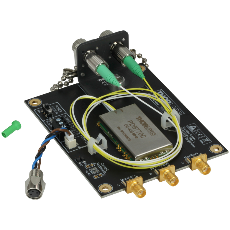
Click to Enlarge
Figure G3.2 A PDB770C balanced amplified detector soldered to a PDBEVAL1 evaluation board. An ADAFCB4 fiber bracket and two plastic clamps are used to mount the fibers.
Click to Enlarge
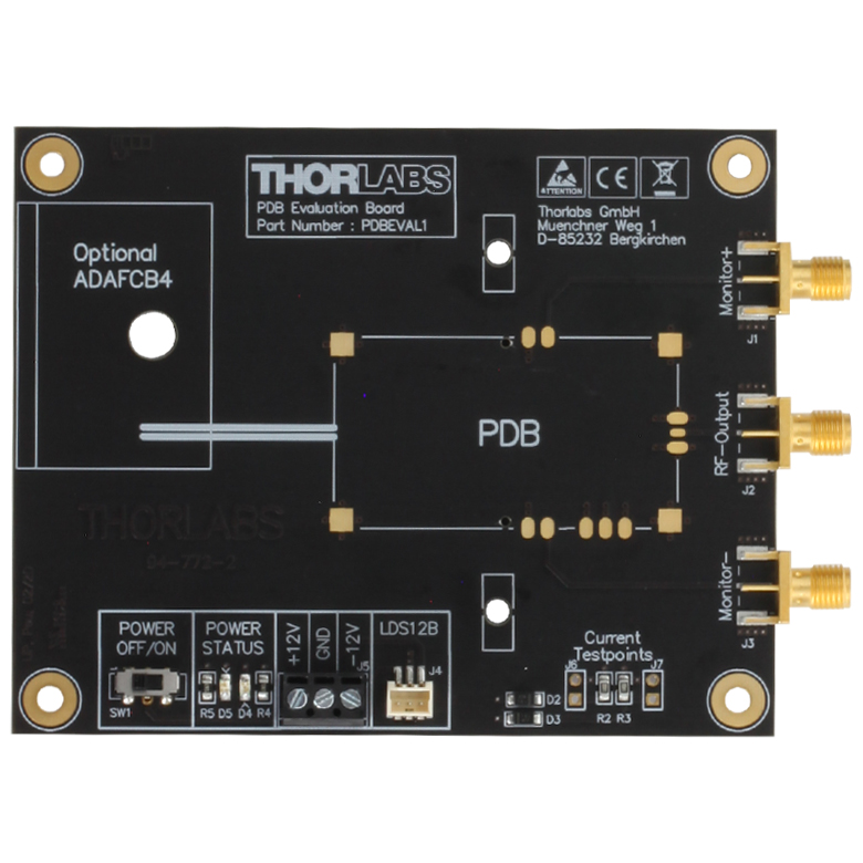
Figure G3.1 Top View of the PDBEVAL1 Evaluation Board
| Table G3.3 Key Specs | |||
|---|---|---|---|
| Full Specsa | Power Supply Voltage | Power Supply Currentb | RF Connectors |
| ±(12 V ± 10%) | ±50 mA (Typ.) ±200 mA (Max) |
SMA up to 5 GHz | |
- Click the blue info icon () for complete specifications.
- Dependent on PDB Module
- Printed Circuit Board (PCB) for Mounting the PDB77xC and PDB78xCAC Detectors
- SMA Connectors with Output and Monitor Signals
- Includes RKMF3 Cable for Connection to Power Supply
- Footprint: 112.6 mm x 80.0 mm x 13.6 mm
The PDBEVAL1 Evaluation Board allows the user to solder the PDB77xC and PDB78xCAC balanced detectors in place so that power and output connections can be made with common cables and connectors. The half-via contacts around the perimeter of the detector can be soldered to the pre-defined contact points on the evaluation board. The board also features three SMA connectors for the monitor and output signals, as well as a screw terminal block and power cable connector for the power supply. The evaluation board also has a slot for an optional ADAFCB4 fiber mounting bracket.
Included with each evaluation board is an RKMF3 connector cable for connecting the Thorlabs LDS12B Power Supply (not included) and two plastic clamps for fiber mounting. Please refer to the PDBEVAL1 spec sheet for complete instructions on connecting and operating a PDBEVAL1 Evaluation Board.
The components inside the detector modules are ESD sensitive. Take all appropriate precautions to discharge personnel and equipment before making any electrical connections to the unit. All soldering must be done by hand; a reflow oven will damage the device.