 Products Home
Continuous Rotation Stage
- Fine Pitch Worm Gear Provides 360° Continuous Rotation
- Compatible with Prism Mounting Hardware
- Vernier Scale Offers 5 arcmin Resolution
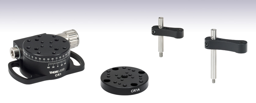
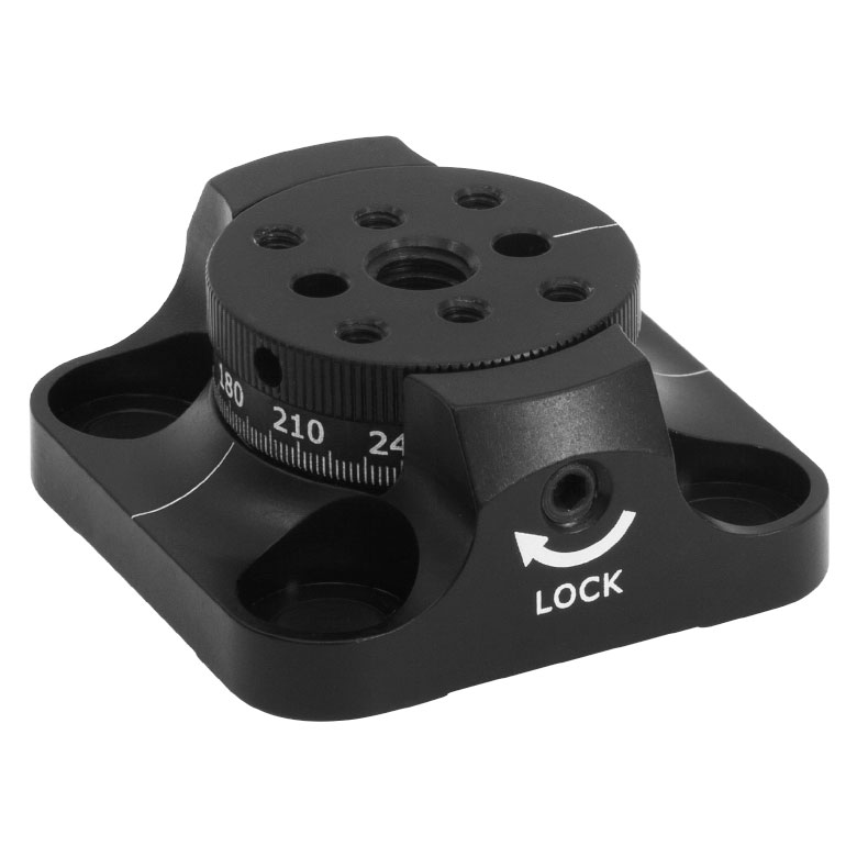
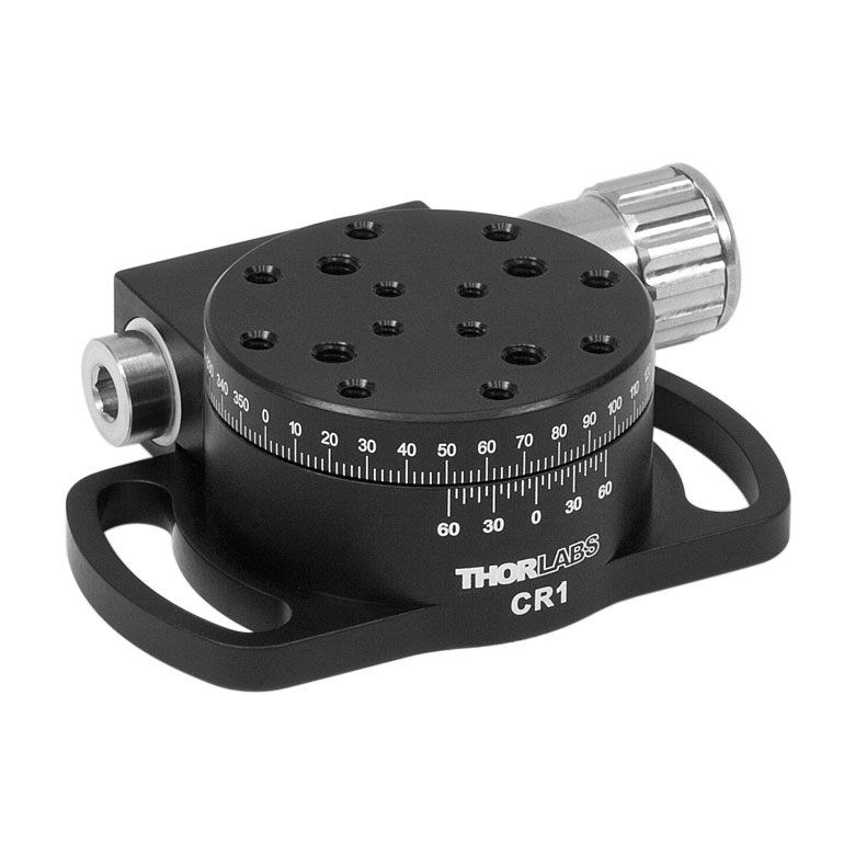
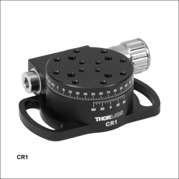
CR1
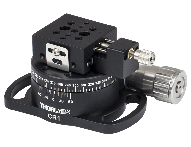
Continuous Rotation Stage
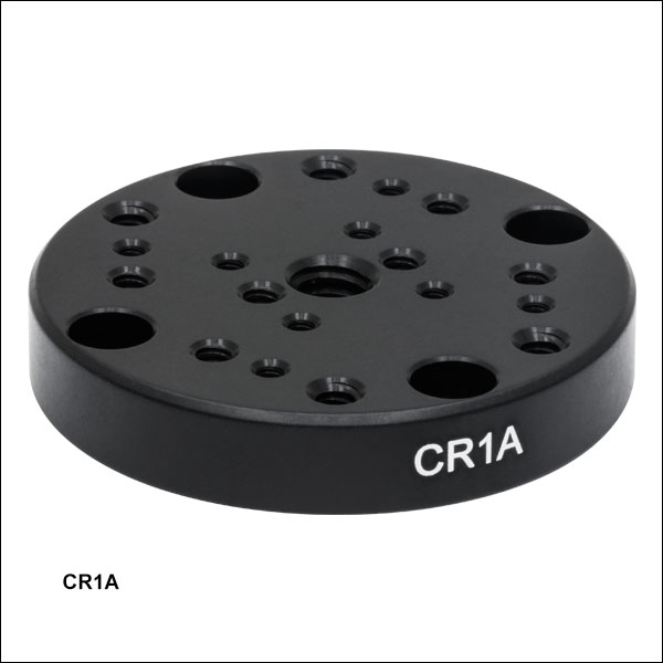
CR1A
General-Purpose Adapter Plate
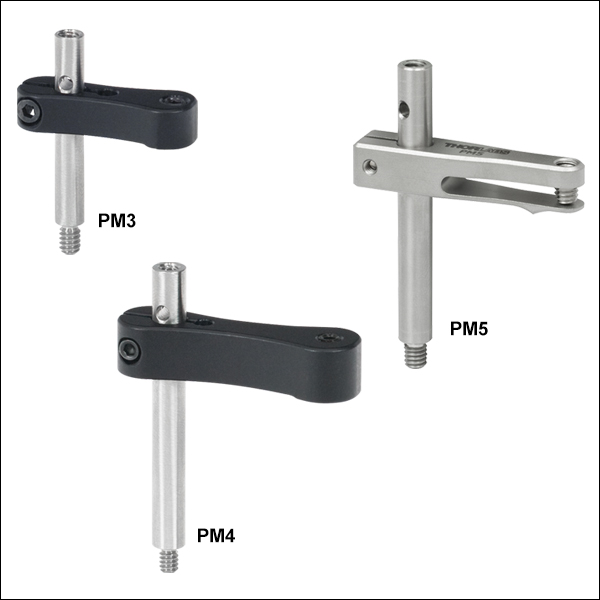
PM3
PM4


Please Wait

| Specifications | ||
|---|---|---|
| Item # | CR1 | CR1/M |
| Rotation Range | 360°, Continuous | |
| Load Capacity | 25 lbs (11.3 kg) | |
| Platform Size | Ø1.70" (Ø43.2 mm) | |
| Platform Mounting Holes |
8-32 (4 Places) 6-32 (8 Places) 4-40 (4 Places) |
M4 x 0.7 (12 Places) 4-40 (4 Places) |
| Base Mounting Holes | Two 1.00" (25.4 mm) Radial Slots for 1/4"-20 (M6 x 1.0) Cap Screws |
|
| Overall Dimensions |
3.14" x 2.10" x 1.00" (79.7 mm x 53.4 mm x 25.4 mm) |
|
Click to Enlarge
Figure 1.1 An MS1 Translation Stage is Mounted onto a CR1 Rotation Stage using two clearance holes for 4-40 cap screws.
Features
- 360° Continuous, Backlash-Free Motion Provided by Fine Pitch Worm Gear
- Vernier Scale Offers a Resolution of 5 arcmin
- 24:1 Gear Ratio Provides 15° Stage Rotation per Revolution of Adjustment Knob
- Application Tested to 25 lbs (11.3 kg) Vertical Load
- Designed for Mounting MS1 and T12 Series Translation Stages (Using the CR1A(/M) Adapter Plate)
- Compatible with Prism Mounting Hardware (See Below)
Thorlabs' CR1(/M) Rotation Stage includes a fine pitch worm gear that provides high-precision and backlash-free rotation. The stage is actuated using a stainless adjuster knob located on the side of the unit that provides 15° of stage rotation per revolution of the adjuster knob. The rotating platform contains an array of 8-32 (M4), 6-32, and 4-40 tapped holes for general mounting requirements. Two radially shaped 1/4" (M6) slots machined in the base provide flexible mounting options and are spaced for compatiblity with imperial and metric optical tables and breadboards.
The easy-to-read radial scale is marked in 2° increments and labeled every 10°. A side-located vernier scale improves resolution to 5 arcmin. The added ability to stack some of our translation stages on the rotation platform, and its 25 lbs (11.3 kg) capacity, make this stage useful in any laboratory.
Click to Enlarge
Figure 2.1 CR1 Packaging

| Table 2.2 Smart-Pack Packaging | ||
|---|---|---|
| Item # | % Weight Reduction |
CO2-Equivalent Reductiona |
| CR1 | 40.48% | 9.07 kg |
| CR1/M | 40.48% | 12.25 kg |
Smart Pack
- Reduce Weight of Packaging Materials
- Increase Usage of Recyclable Packing Materials
- Improve Packing Integrity
- Decrease Shipping Costs
Thorlabs' Smart Pack Initiative is aimed at waste minimization while still maintaining adequate protection for our products. By eliminating any unnecessary packaging, implementing packaging design changes, and utilizing eco-friendly packaging materials for our customers when possible, this initiative seeks to improve the environmental impact of our product packaging. The products listed in Table 2.2 are now shipped in re-engineered packaging that minimizes the weight and the use of non-recyclable materials.b As we move through our product line, we will indicate re-engineered packages with our Smart Pack logo.
Reading a Vernier Scale on a Linear Main Scale
Vernier scales are typically used to add precision to standard, evenly divided scales (such as the scales on Thorlabs' rotation, goniometric, or translation mounts). A vernier scale has found common use in many precision measurement instruments, the most common being calipers and micrometers. The vernier scale uses two scales side-by-side: the main scale and the vernier scale. The direct vernier scale has a slightly smaller spacing between its tick marks owing to the vernier scale having N ticks for every N - 1 ticks on the main scale. Hence, the lines on the main scale will not line up with all the lines on the vernier scale. Only one line from the vernier scale will match well with one line of the main scale, and that is the trick to reading a vernier scale.
Figures 130A through 130C show a linear vernier scale system for three different situations. In each case, the scale on the left is the main scale, while the small scale on the right is the vernier scale. When reading a vernier scale, the main scale is used for the gross number, and the vernier scale gives the precision value. In this manner, a standard ruler or micrometer can become a precision instrument.
The 0 on the vernier scale is the "pointer" (marked by a red arrow in Figures 130A through 130E) and will indicate the main scale reading. In Figure 130A we see the pointer is lined up directly with the 75.6 line. Notice that the only other vernier scale tick mark that lines up well with the main scale is 10. Since the pointer lines up with the main scale’s 75.6, the reading from Figure 130A is 75.60 (in whatever units the instrument measures).
That is essentially all there is to reading a vernier scale. It's a very straightforward way of increasing the precision of a measurement instrument. To expound, let’s look at Figure 130B. Here we see that the pointer is no longer aligned with a line on the main scale, but instead it is slightly above 75.6 and below 75.7; thus, the gross measurement is 75.6. The first vernier line that coincides with a main scale line is the 5, shown with a blue arrow. The vernier scale gives the final digit of precision; since the 5 is aligned to the main scale, the precision measurement for Figure 130B is 75.65.
Since this vernier scale is 10% smaller than the main scale, moving the vernier scale by 1/10 of the main scale will align the next vernier marking. This asks the obvious question: what if the measurement is within the 1/10 precision of the vernier scale? Figure 130C shows just this. Again, the pointer line is in between 75.6 and 75.7, yielding the gross measurement of 75.6. If we look closely, we see that the vernier scale 7 (marked with a blue arrow) is very closely aligned to the main scale, giving a precision measurement of 75.67. However, the vernier scale 7 is very slightly above the main scale mark, and we can see that the vernier scale 8 (directly above 7) is slightly below its corresponding main scale mark. Hence, the scale on Figure 130C could be read as 75.673 ± 0.002. A reading error of about 0.002 would be appropriate for
this instrument.
Click to Enlarge
Figure 130A An example of how to read a vernier scale. The red arrow indicates what is known as the pointer. Since the tick mark labeled 10 on the vernier scale aligns with one of the tick marks on the main scale, this vernier scale is reading 75.60 (in whatever units the instrument measures).

Click to Enlarge
Figure 130B The red arrow indicates the pointer and the blue arrow indicates the vernier line that matches the main scale. This scale reads 75.65.
Click to Enlarge
Figure 130C The red arrow indicates the pointer, and the blue arrow indicates the vernier line that matches the main scale. This scale reads 75.67 but can be accurately read as
75.673 ± 0.002.
Reading a Vernier Scale on a Rotating Main Scale
The vernier scale may also be used on rotating scales where the main scale and vernier scale do not share units. Figures 130D and 130F show a vernier scale system for two different situations where the main scale is given in degrees and the vernier scale has ticks every 5 arcmin (60 arcmin = 1°). In each case, the scale on the top is the main scale, while the small scale on the bottom is the vernier scale.
In Figure 130D we see the pointer is lined up directly with the 341° line. Notice that the only other vernier scale tick marks that line up well with the main scale are ±60 arcmin. Since the pointer lines up with the main scale at 341°, the reading from Figure 130D is 341.00°.
There are two ways to determine the reading if the zero on the vernier scale line is between two lines of the main scale. For the first method, take the line on the left side of the pointer on the vernier scale and subtract that value (in arcmin) from the value on the main scale that is to the right on the main scale. As an example, in Figure 130E the vernier pointer is between 342° and 343°; using the left blue arrow of the vernier scale results in
As we've seen here, vernier scales add precision to a standard scale measurement. While it takes a bit of getting used to, with a little practice, reading these scales is fairly straightforward. Vernier scales, whether they are direct or retrograde*, are read in the same fashion.
*A retrograde vernier scale has a larger spacing between its tick marks with N ticks for every N + 1 ticks on the main scale.
Click to Enlarge
Figure 130D An example of a vernier scale where the main scale and the vernier scale are in different units (degrees and arcmins, respectively). The red arrow indicates the pointer. This scale reads 341.00°.
Click to Enlarge
Figure 130E The red arrow indicates the pointer and the blue arrows give the precision value from the vernier scale.
This scale reads 342.75°.
| Posted Comments: | |
Andrey Kuznetsov
(posted 2024-05-06 17:29:28.183) I have multiple CR1 stages and they suffer from multiple problems. An optical post mounted on the stage wobbles pretty badly, there is also severe backlash, and the worm drive does not operate smoothly, it would get more difficult to turn within certain ranges. Grease has also leaked out of the stages. cdolbashian
(posted 2024-05-10 04:26:04.0) Thank you for reaching out to us with this inquiry Andrey. I have contacted you directly to have you expound on these issues and share your experience with us. |
Rotation Mount and Stage Selection Guide
Thorlabs offers a wide variety of manual and motorized rotation mounts and stages. Rotation mounts are designed with an inner bore to mount a Ø1/2", Ø1", or Ø2" optic, while rotation stages are designed with mounting taps to attach a variety of components or systems. Motorized options are powered by a DC Servo motor, 2 phase stepper motor, piezo inertia motor, or an Elliptec™ resonant piezo motor. Each offers 360° of continuous rotation.
Manual Rotation Mounts
| Rotation Mounts for Ø1/2" Optics | |||||||
|---|---|---|---|---|---|---|---|
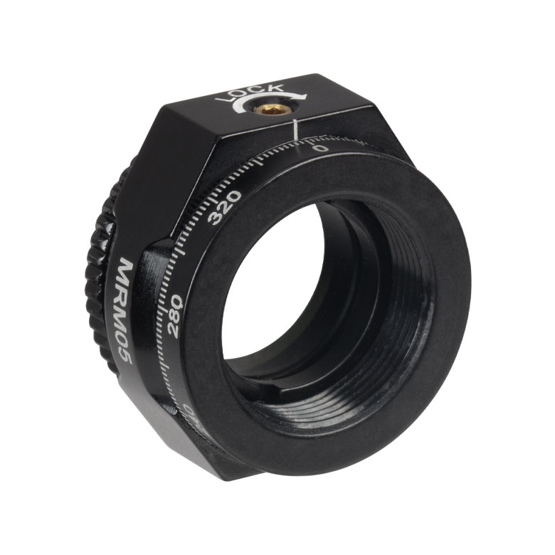
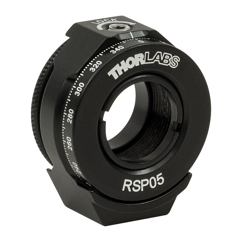
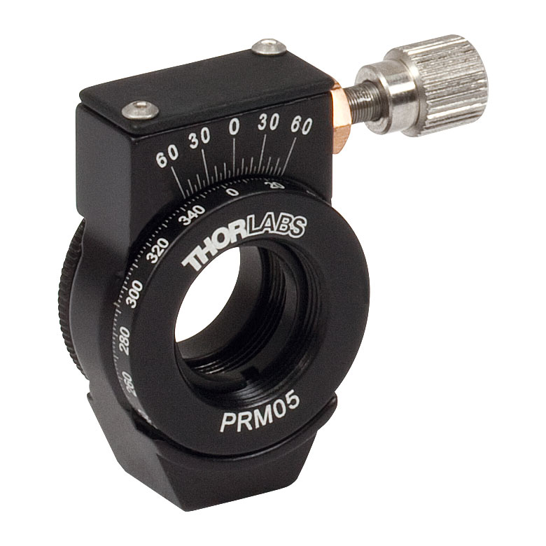
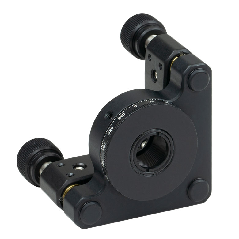
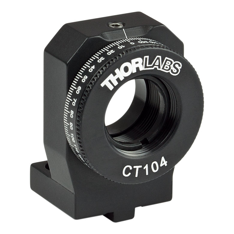
| Item # | MRM05(/M) | RSP05(/M) | CRM05 | PRM05(/M)a | SRM05 | KS05RS | CT104 |
| Click Photo to Enlarge |
 |
 |
 |
 |
 |
 |
 |
| Features | Mini Series | Standard | External SM1 (1.035"-40) Threads |
Micrometer | 16 mm Cage-Compatible | ±4° Kinematic Tip/Tilt Adjustment Plus Rotation | Compatible with 30 mm Cage Translation Stages and 1/4" Translation Stagesb |
| Additional Details | |||||||
| Rotation Mounts for Ø1" Optics | ||||||||
|---|---|---|---|---|---|---|---|---|
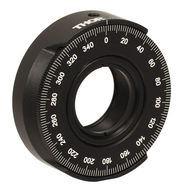
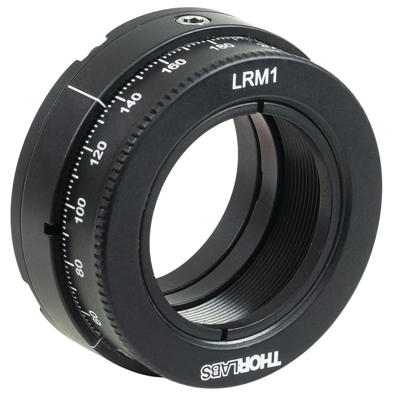
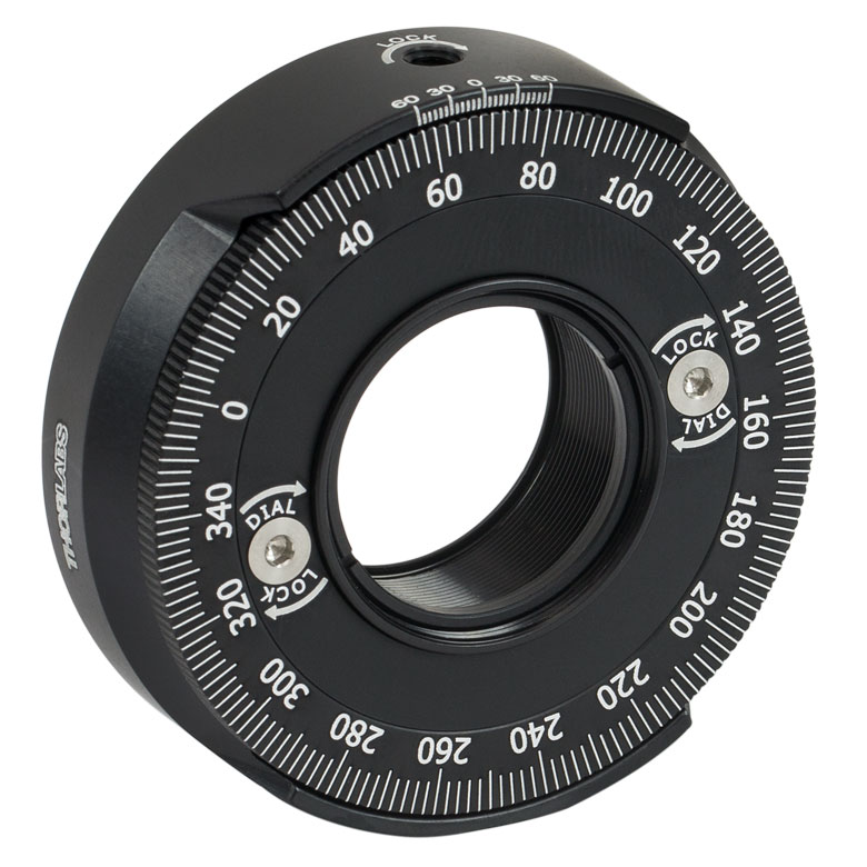
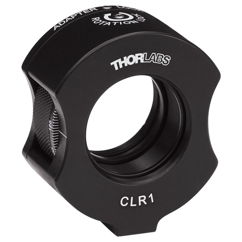
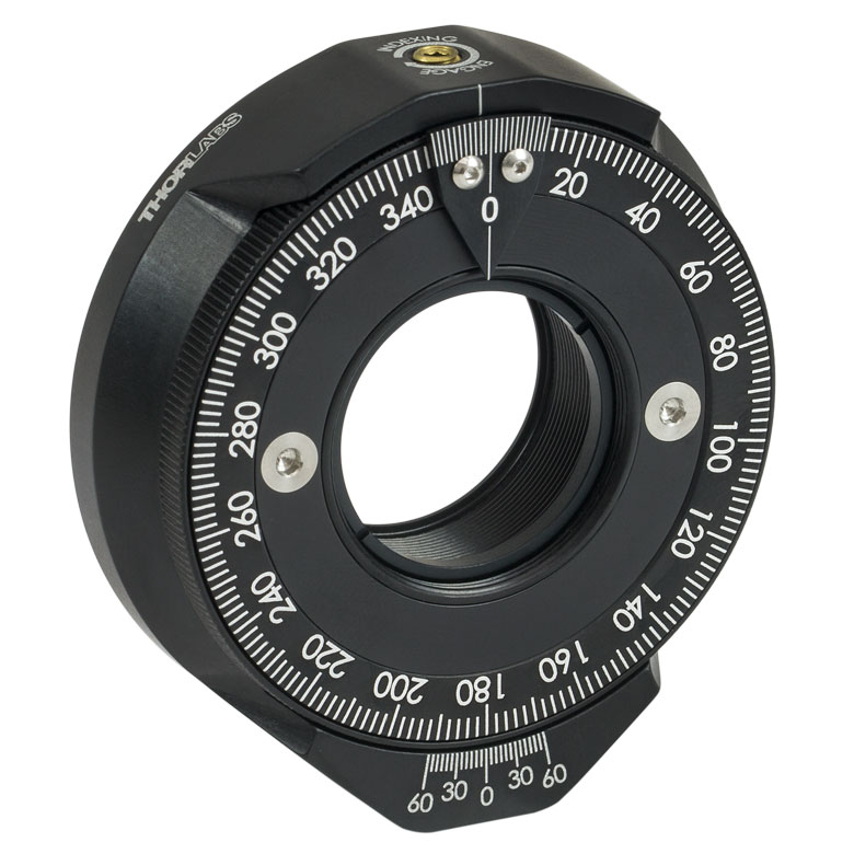
| Item # | RSP1(/M) | LRM1 | RSP1D(/M) | DLM1(/M) | CLR1(/M) | RSP1X15(/M) | RSP1X225(/M) | PRM1(/M)a |
| Click Photo to Enlarge |
 |
 |
 |
 |
 |
 |
|
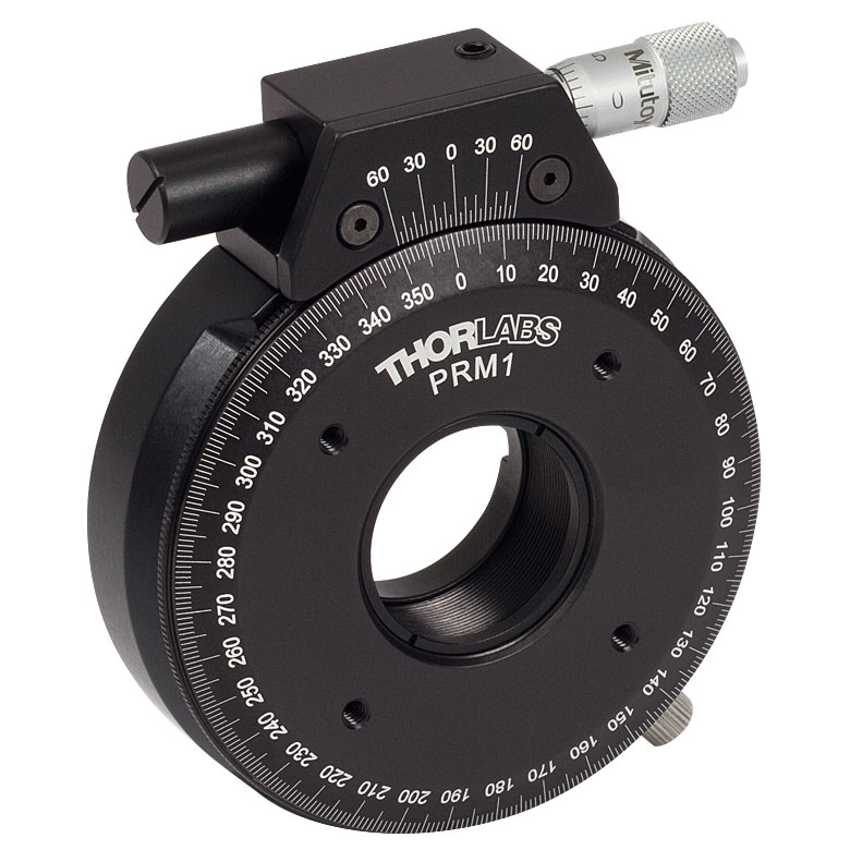 |
| Features | Standard | External SM1 (1.035"-40) Threads |
Adjustable Zero | Two Independently Rotating Carriages | Rotates Optic Within Fixed Lens Tube System |
Continuous 360° Rotation or 15° Increments |
Continuous 360° Rotation or 22.5° Increments |
Micrometer |
| Additional Details | ||||||||
| Rotation Mounts for Ø1" Optics | ||||||
|---|---|---|---|---|---|---|
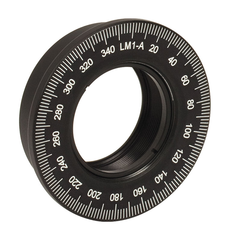
| Item # | LM1-A & LM1-B(/M) |
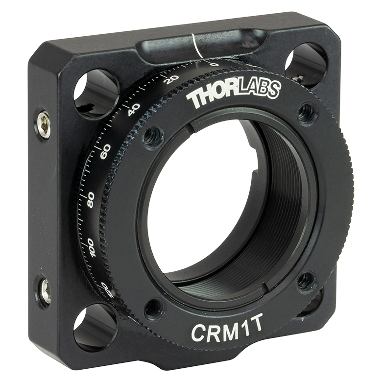
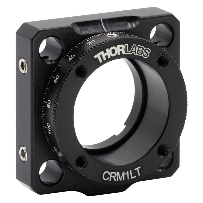
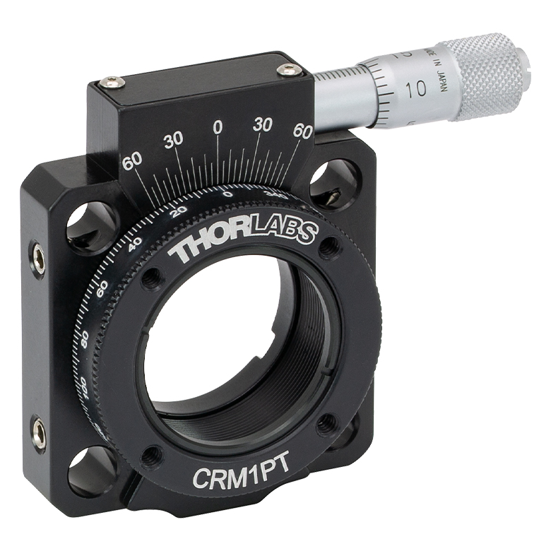
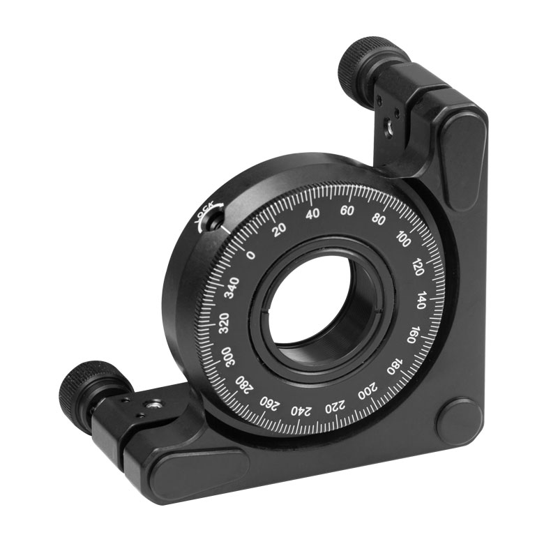
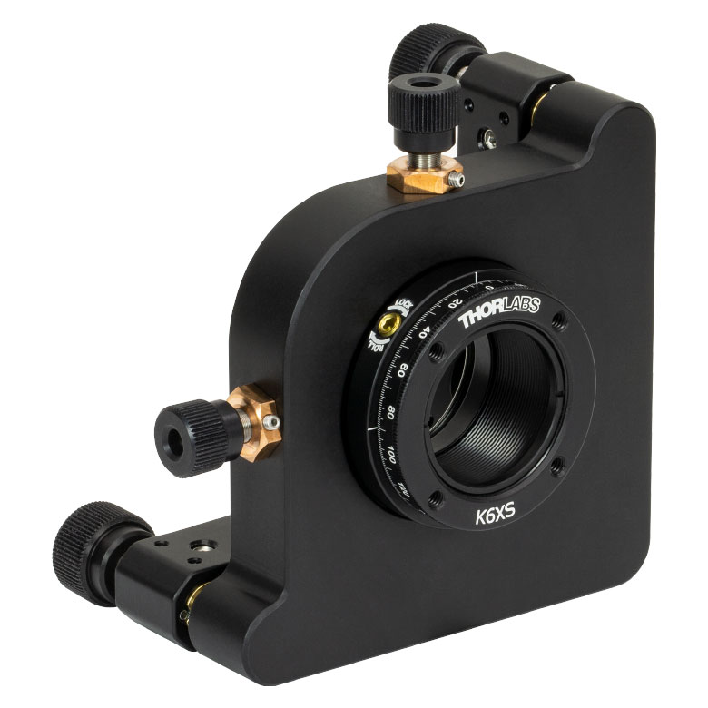
CRM1T(/M) | CRM1LT(/M) | CRM1PT(/M) | KS1RS | K6XS |
| Click Photo to Enlarge |
  |
 |
 |
 |
 |
 |
| Features | Optic Carriage Rotates Within Mounting Ring | 30 mm Cage-Compatiblea | 30 mm Cage-Compatible for Thick Opticsa |
30 mm Cage-Compatible with Micrometera |
±4° Kinematic Tip/Tilt Adjustment Plus Rotation | Six-Axis Kinematic Mounta |
| Additional Details | ||||||
| Rotation Mounts for Ø2" Optics | |||||||
|---|---|---|---|---|---|---|---|
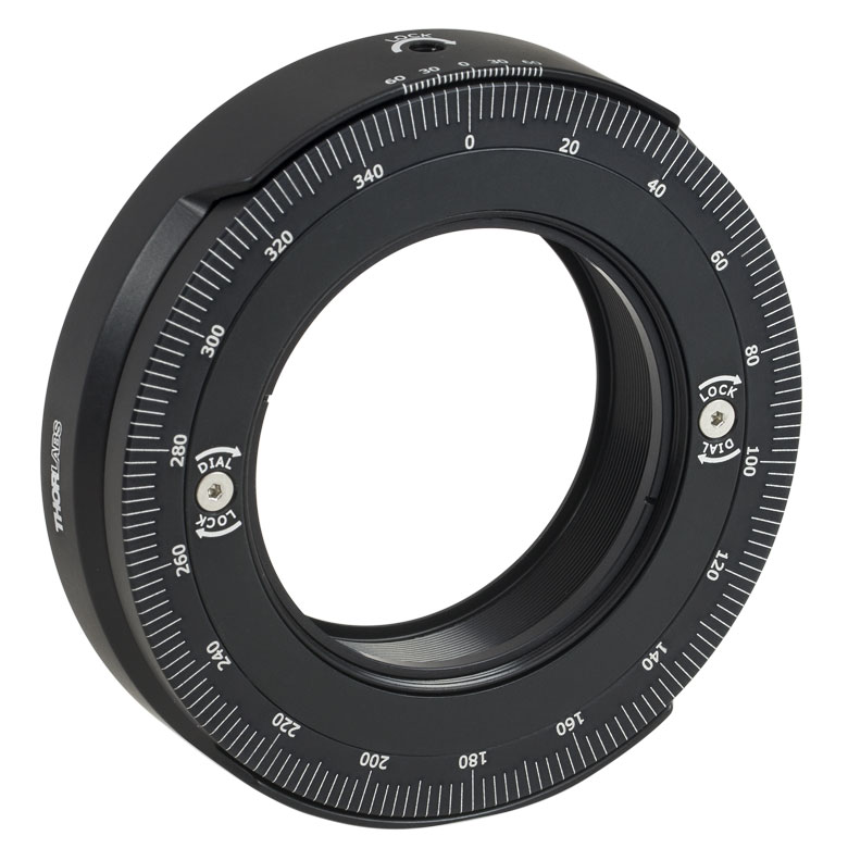
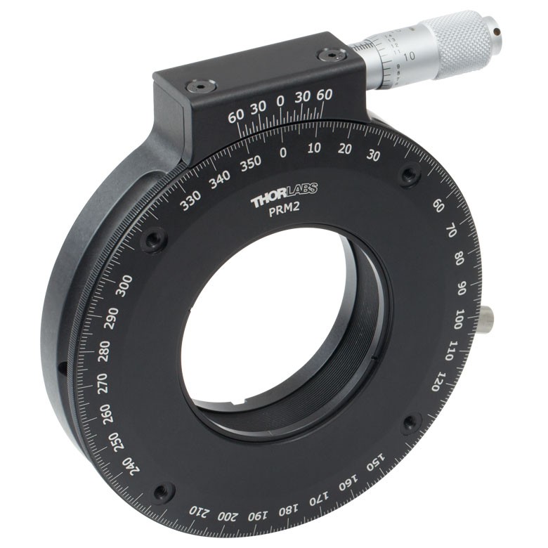
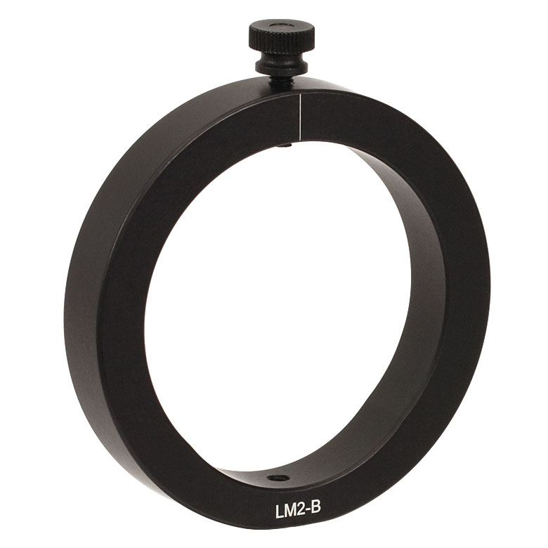
| Item # | RSP2(/M) | RSP2D(/M) | PRM2(/M) | LM2-A & LM2-B(/M) |
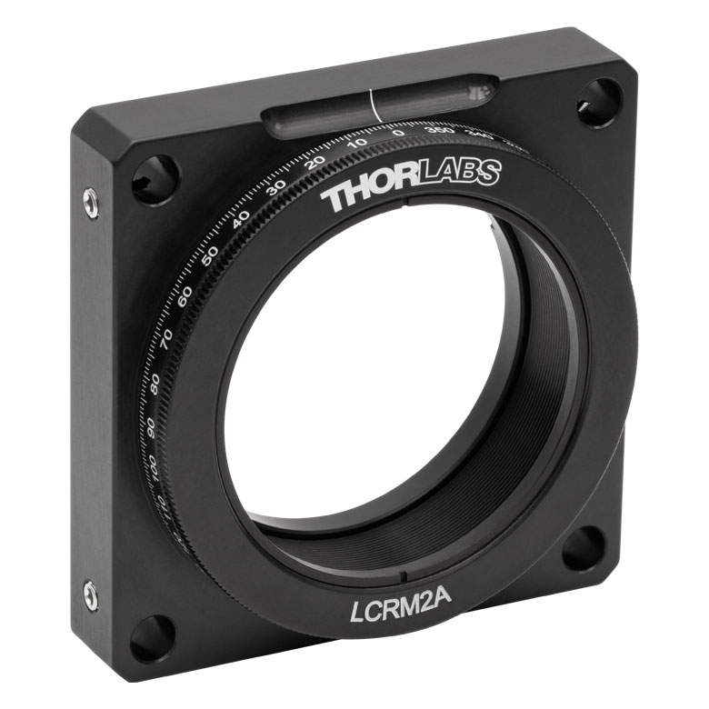
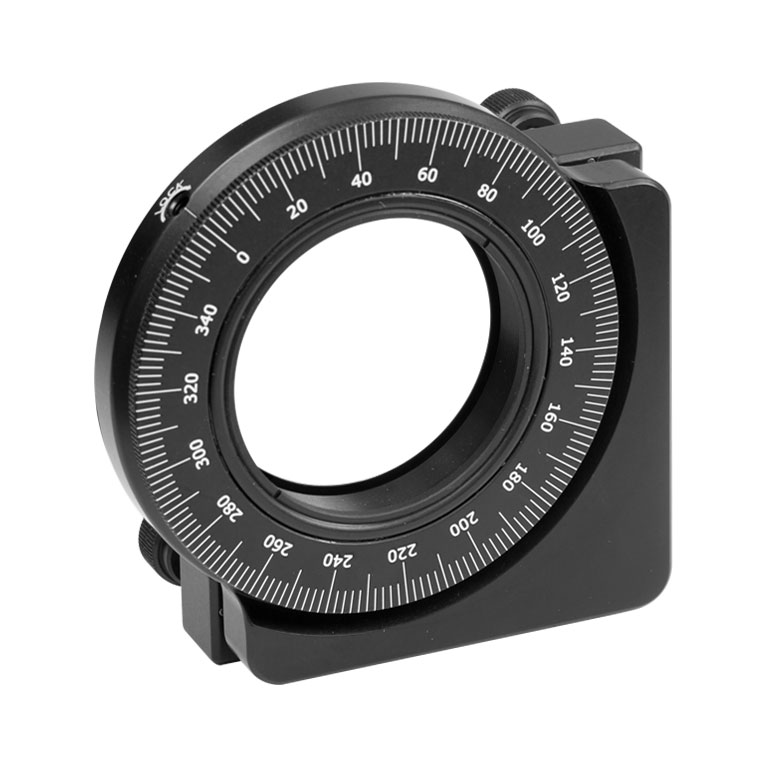
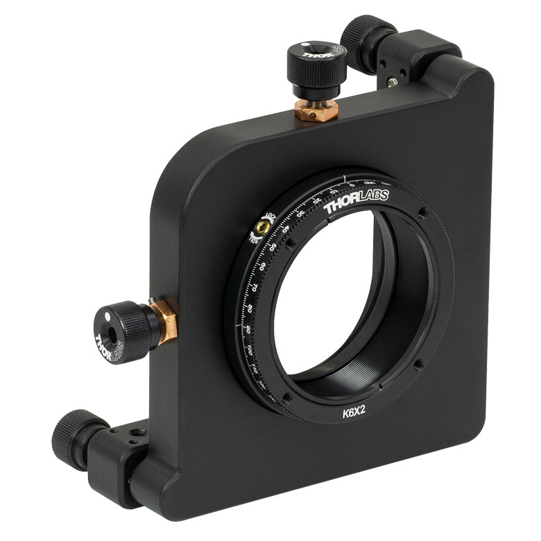
LCRM2A(/M) | KS2RS | K6X2 |
| Click Photo to Enlarge | 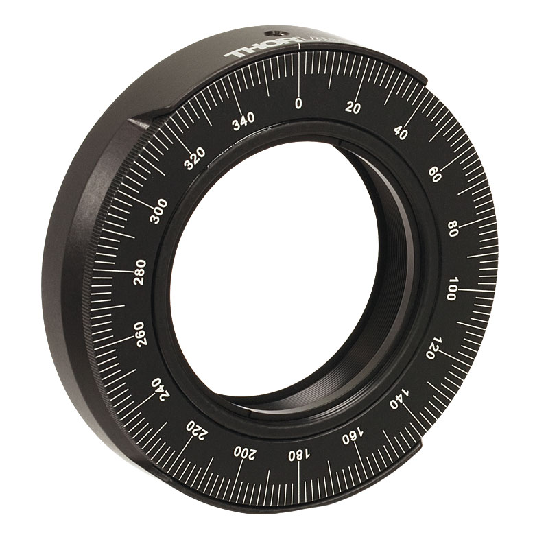 |
 |
 |
  |
 |
 |
 |
| Features | Standard | Adjustable Zero |
Micrometer | Optic Carriage Rotates Within Mounting Ring | 60 mm Cage-Compatible | ±4° Kinematic Tip/Tilt Adjustment Plus Rotation | Six-Axis Kinematic Mount |
| Additional Details | |||||||
Manual Rotation Stages
| Manual Rotation Stages | ||||||
|---|---|---|---|---|---|---|
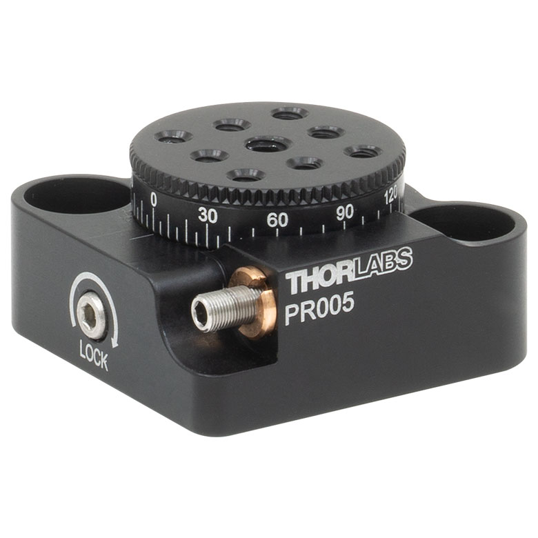
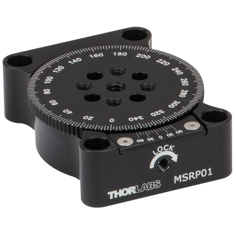
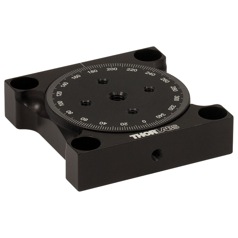
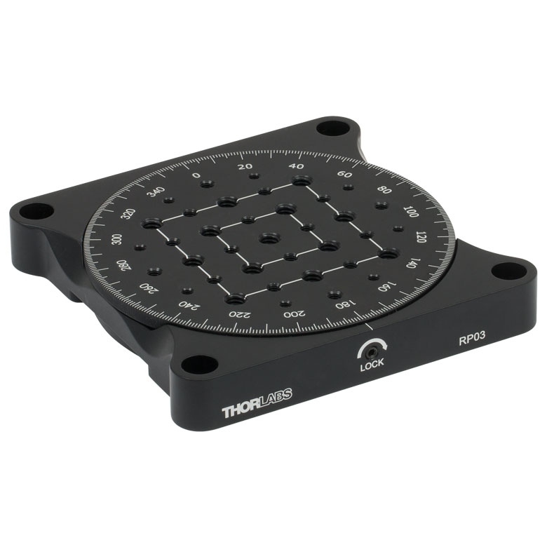
| Item # | RP005(/M) | PR005(/M) | MSRP01(/M) | RP01(/M) | RP03(/M) | QRP02(/M) |
| Click Photo to Enlarge |
 |
 |
 |
 |
 |
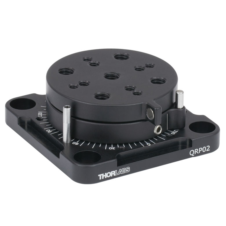 |
| Features | Standard | Two Hard Stops | ||||
| Additional Details | ||||||
| Manual Rotation Stages | ||||||
|---|---|---|---|---|---|---|
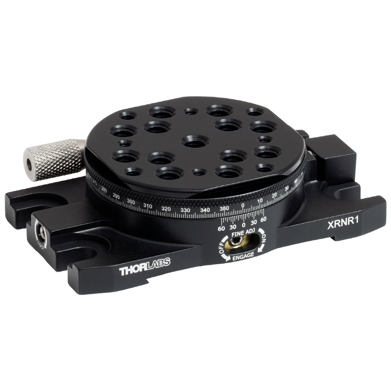
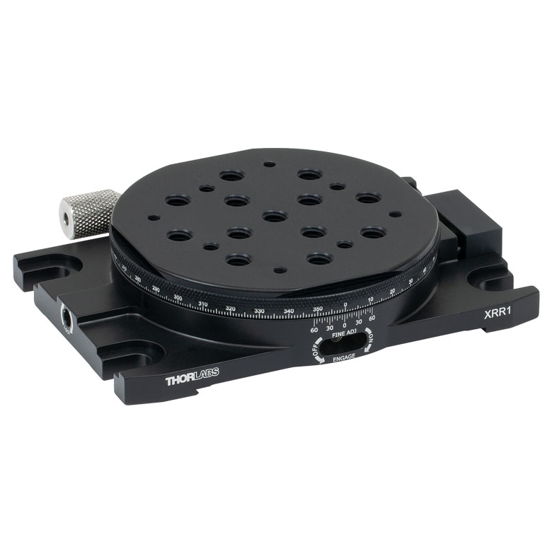
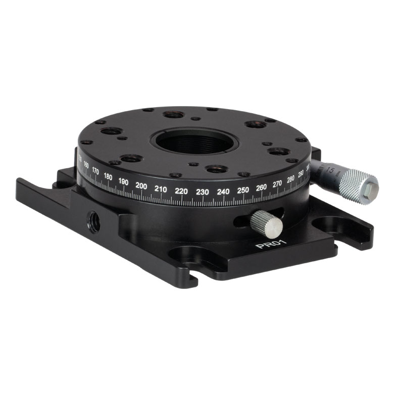
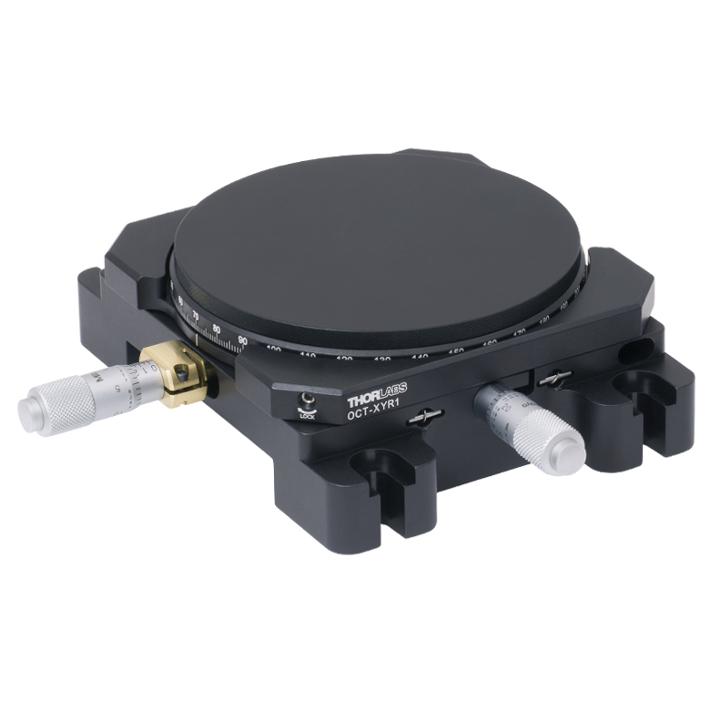
| Item # | XRNR1(/M) | XRR1(/M) | PR01(/M) | CR1(/M) | XYR1(/M) | OCT-XYR1(/M) |
| Click Photo to Enlarge |
 |
 |
 |
 |
 |
 |
| Features | Fine Rotation Adjuster and 2" Wide Dovetail Quick Connect |
Fine Rotation Adjuster and 3" Wide Dovetail Quick Connect |
Fine Rotation Adjuster and SM1-Threaded Central Aperture |
Fine Pitch Worm Gear | Rotation and 1/2" Linear XY Translation | |
| Additional Details | ||||||
Motorized Rotation Mounts and Stages
| Motorized Rotation Mounts and Stages with Central Clear Apertures | |||||
|---|---|---|---|---|---|
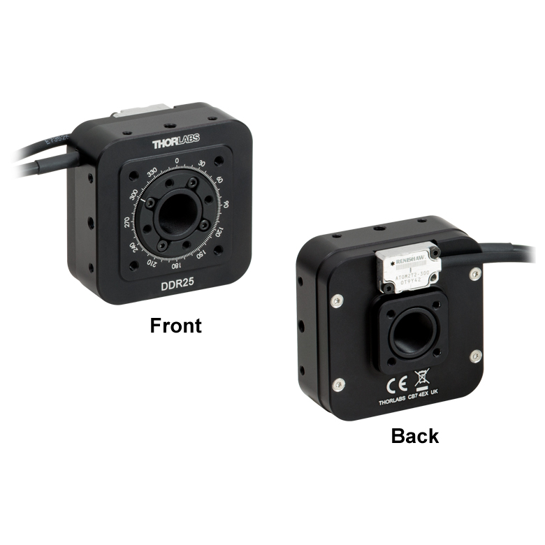
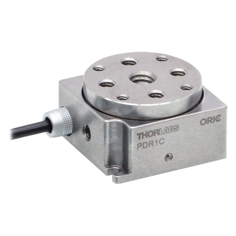
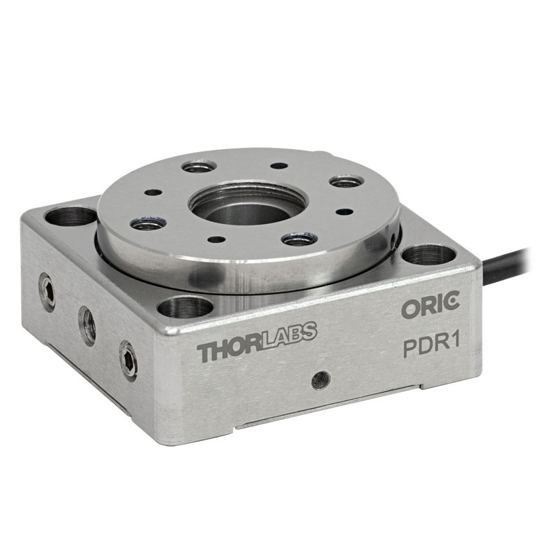
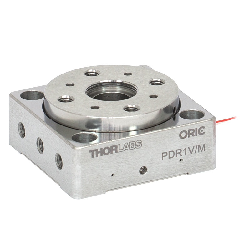
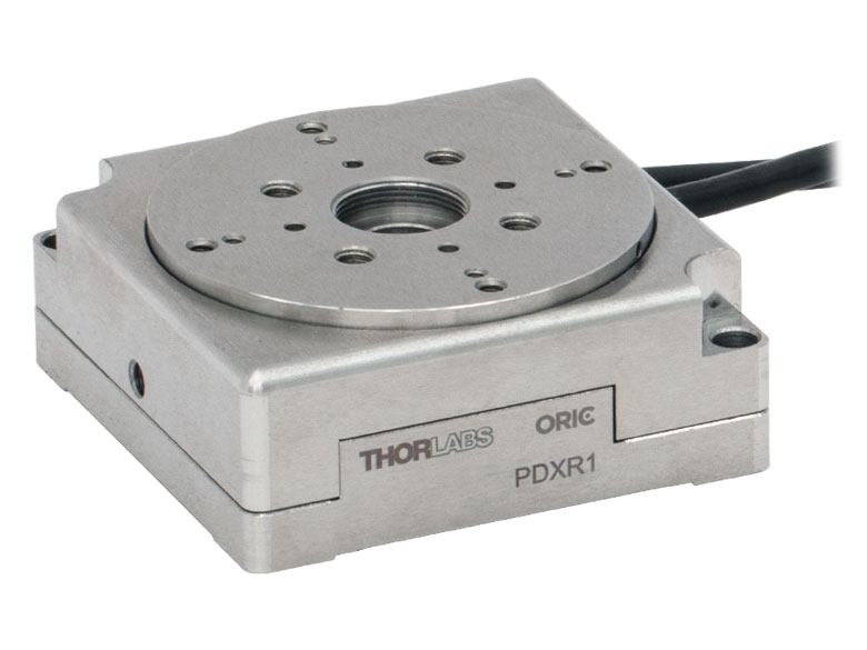
| Item # | DDR25(/M) | PDR1C(/M) | PDR1(/M) | PDR1V(/M) | PDXR1(/M) |
| Click Photo to Enlarge |
 |
 |
 |
 |
 |
| Features | Compatible with SM05 Lens Tubes, 16 mm Cage System, & 30 mm Cage System |
Compatible with 16 mm Cage System |
Compatible with SM05 Lens Tubes & 30 mm Cage System |
Vacuum-Compatible; Also Compatible with SM05 Lens Tubes & 30 mm Cage System |
Compatible with SM05 Lens Tubes & 30 mm Cage System |
| Additional Details | |||||
| Motorized Rotation Mounts and Stages with Central Clear Apertures | |||||||
|---|---|---|---|---|---|---|---|
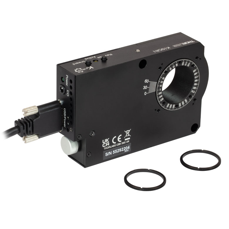
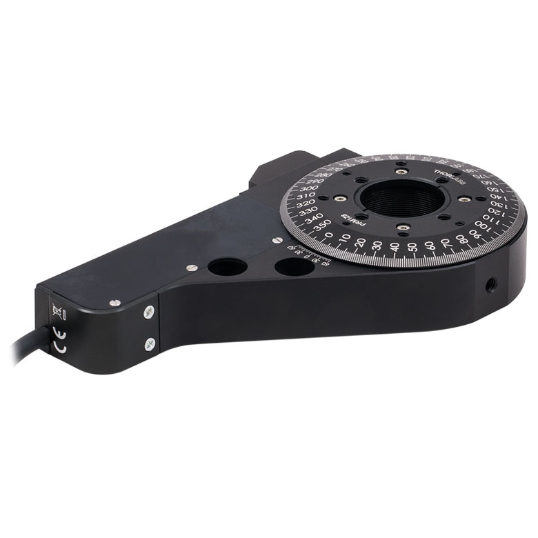
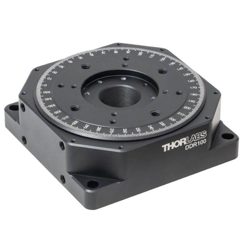
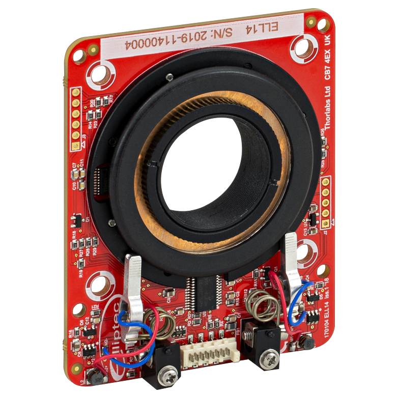
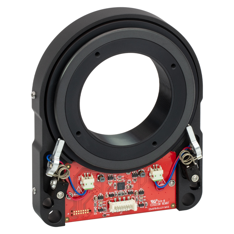
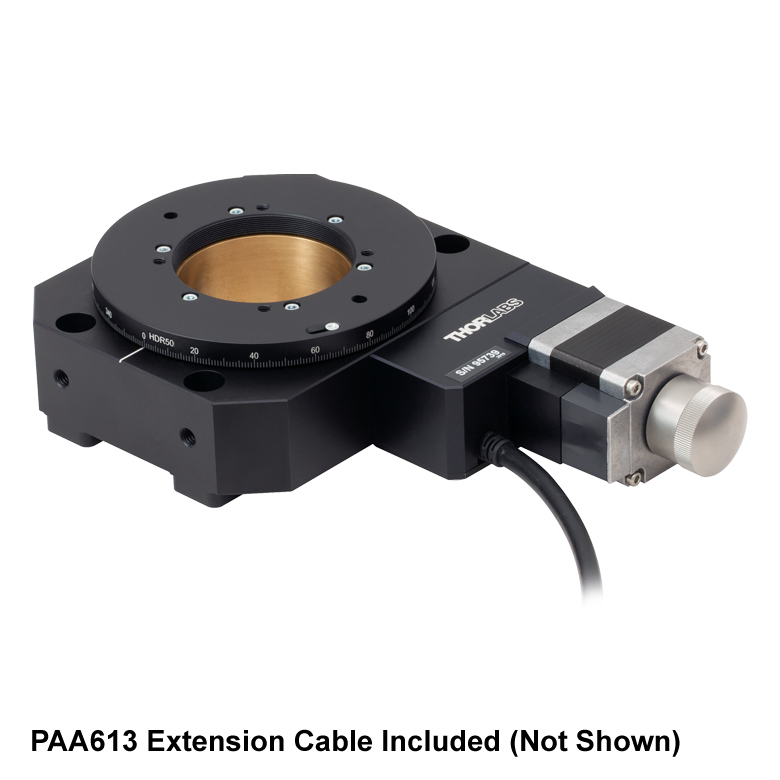
| Item # | K10CR1(/M) | PRM1Z8(/M)a | DDR100(/M) | ELL16 | ELL14 | ELL21(/M) | HDR50(/M) |
| Click Photo to Enlarge |
 |
 |
 |
 |
 |
 |
 |
| Features | Compatible with SM1 Lens Tubes & 30 mm Cage System | Compatible with SM1 Lens Tubes, 16 mm Cage System, 30 mm Cage System |
Compatible with SM05 Lens Tubes, Open Frame Design for OEM Applications |
Compatible with SM1 Lens Tubes, Open Frame Design for OEM Applications |
Compatible with SM2 Lens Tubes, Open Frame Design for OEM Applications |
Compatible with SM2 Lens Tubes |
|
| Additional Details | |||||||
| Motorized Rotation Mounts and Stages with Tapped Platforms | ||
|---|---|---|
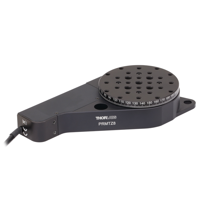
| Item # | PRMTZ8(/M)a | ELL18(/M)b |
| Click Photo to Enlarge |
 |
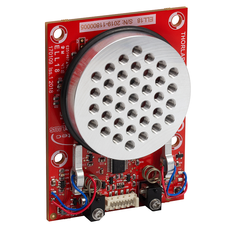 |
| Features | Tapped Mounting Platform for Mounting Prisms or Other Optics | Tapped Mounting Platform, Open Frame Design for OEM Applications |
| Additional Details | ||

 Zoom
Zoom
Click for Details
Figure G1.1 CR1 Mechanical Drawing
- 360° Continuous, Backlash-Free Motion Provided by Fine Pitch Worm Gear
- Vernier Scale Offers a Resolution of 5 arcmin
- 24:1 Gear Ratio Provides 15° Stage Rotation per Revolution of Adjustment Knob
- Application Tested to 25 lbs (11.3 kg) Vertical Load
- Designed for Mounting MS1 and T12 Series Translation Stages (Using the CR1A(/M) Adapter Plate)
- Compatible with Prism Mounting Hardware
The CR1(/M) rotation stage includes a fine pitch worm gear that provides high-precision and backlash-free rotation. The stage is rotated via a polished stainless steel adjuster knob located on the side of the unit. The easy-to-read radial scale is marked in 2° increments and labeled every 10°. A side-located vernier scale provides resolution to 5 arcmin.
The rotating platform contains an array of 8-32 (M4) and 4-40 tapped holes. In addition, eight 6-32 (M4) taps are located 17.5 mm from the center of the platform; using a PM3(/M) clamping arm in one of these taps will locate the clamping arm's nylon-tipped setscrew directly above the center.
The CR1(/M) has two radially shaped 1/4" (M6) slots machined in the base so that it can be mounted to an optical table or breadboard.
The rotation stage is capable of operating with a mounted load of up to 25 lbs (11.3 kg). MS1 series and T12 series translation stages can be mounted on top of the rotating platform with the use of a CR1A(/M) adapter plate.

 Zoom
Zoom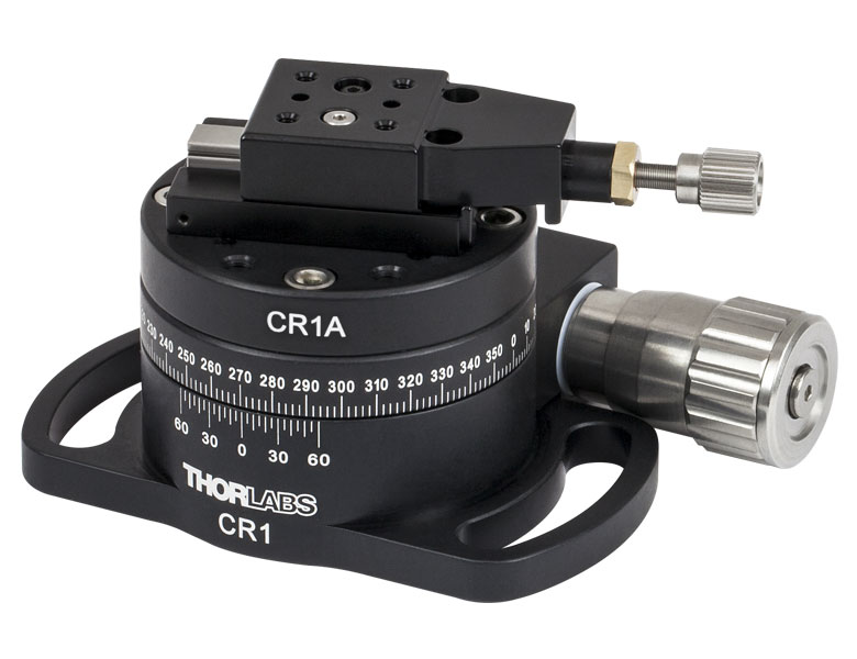
Click to Enlarge
Figure G2.1 A CR1A Adapter is used to secure a T12X Mini Translator onto a CR1 Rotation Stage using two 2-56 cap screws.
The CR1A(/M) adapter can be used to secure select Thorlabs mounts to the CR1(/M) Rotation stage. The adapter is equipped with four
The CR1A(/M) adapter is attached to the CR1(/M) stage via the #6 (M4) clearance holes with four 6-32 (M4) cap screws (included). Figure G2.1 shows a T12X translation stage mounted on the CR1A adapter through two #2 (M2) clearance holes in the bottom of the T12X stage.
| Table G2.2 Mounts Compatible with CR1A(/M) Adapter | |
|---|---|
| Mount | Description |
| PM3(/M), PM4(/M), and PM5(/M) | Clamping Arms |
| PH Series | Post Holders |
| T12 Series | 1/2" Mini Translators |
| GN Seriesa | Small Platform Goniometers* |

 Zoom
Zoom
Click for Details
Figure 756A Mechanical Drawings
- Provide Clamping Force for Our Platform Mounts
- Threaded Hole on Top and Threaded Stud on Bottom of Post
- 6-32 Threads on PM3 and PM4
- 8-32 Threads on PM5
- M4 x 0.7 Threads on All Metric Versions
- Maximum Optic Heights from 0.97" to 1.65" (24.6 mm to 41.8 mm)
- Extension Posts Available to Increase Max Optic Height
- PM3SP(/M) with PM3(/M): Hold Optics up to 2.21" (56.1 mm) Tall
- PM4SP(/M) with PM4(/M): Hold Optics up to 3.61" (91.7 mm) Tall
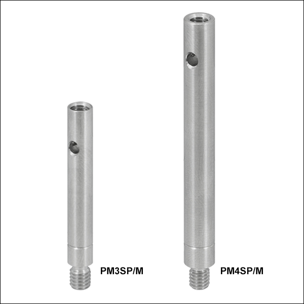
Click to Enlarge
Figure 756B Clamping Arm Extension Posts with Metric Indicator Groove
Thorlabs' Clamping Arms provide clamping force to secure optics to our kinematic platform mounts, stages, and V-clamps. The PM3(/M) accommodates optics up to 0.97" tall and features a 0.69" center-to-center distance between the post and the nylon-tipped setscrew that holds the optic. The PM4(/M) accommodates optics up to 1.61" and features a 1.16" center-to-center distance between the post and the nylon-tipped setscrew. The maximum optic height of the PM3(/M) or PM4(/M) Clamping Arms can be extended using our PM3SP(/M) or PM4SP(/M) Extension Posts, respectively. These extension posts are identical to the posts included in each complete clamping arm. Each clamping arm features 6-32 (M4 x 0.7) threads. The PM3 and PM4 can be mounted in 8-32 tapped holes by using the AS6E8E thread adapter, which features internal 6-32 threads and external 8-32 threads. This thread adapter has an outer diameter of 0.24", which is the same as the PM4SP extension post and the post included with the PM4 clamping arm. This allows the clamping arm to be adjusted across the seam between either post and the adapter. The smaller diameters of the included post for the PM3 clamping arm and the PM3SP extension post cause the thread adapter to act as a stop for the clamping arm.
The PM5(/M) clamping arm is made entirely from heat-treated stainless steel, which helps maintain stability in fluctuating temperatures and provides vacuum compatibility. This clamping arm is recommended for use with the POLARIS-K1M4(/M), but it can be used with any platform mount or stage that has one or more 8-32 (M4 x 0.7) tapped holes. The PM5(/M) can hold optics up to 1.65" tall, and the distance from the post center to the contact point that holds the optic is 0.90".
Each clamping arm is attached to its post using a flexure mechanism that locks with a 5/64" (2.0 mm) balldriver or hex key. The setscrew on top of the clamping arm also accepts a 5/64" (2.0 mm) balldriver or hex key in order to clamp down on the optic. The post includes a through hole which can be leveraged for added torque when tightening down the post. Please see Figure 756A for additional information.