

Motorized High-Load Vertical Translation Stage
- Motorized Stage with 50 mm (1.97") Vertical Travel
- High Load Capacity of 20 kg (44 lbs)
- Integrated Controller Facilitates Local or Remote Control
MLJ250
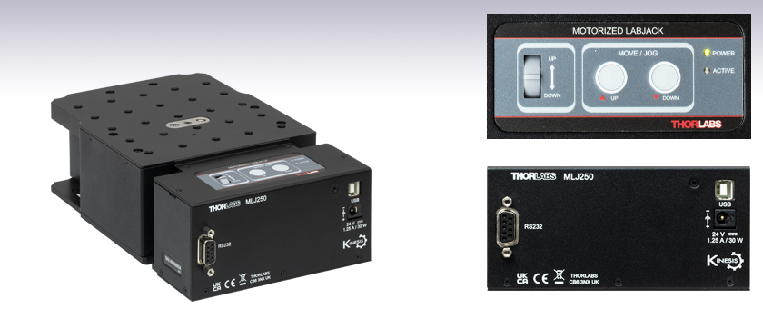
50 mm Vertical Travel Stage with Integrated Controller
Power Supply, USB, and RS232 Ports
Manual Control Keypad
OVERVIEW
| Key Specificationsa | |
|---|---|
| Travel | 50 mm (1.97") |
| Load (Max) | 20 kg (44 lbs) |
| Velocity (Max) | 3.0 mm/s (All Loads) |
| Pitch/Roll Errorb | <500 µRad |
| Unidirectional Repeatabilityc | <10 µm |
| Deck Parallelism | <150 µm Over Full Range of Travel |
Click to Enlarge
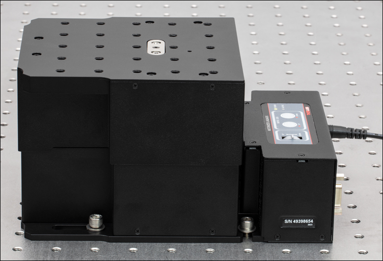
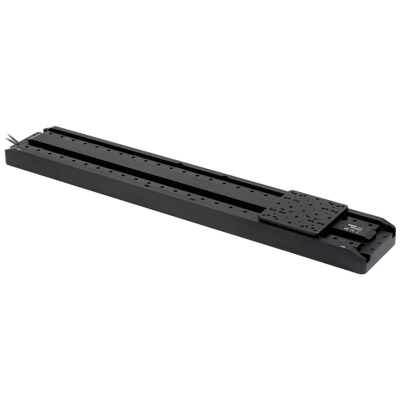
Figure 1.1 The Fully Extended MLJ250(/M) Mounted onto a Nexus Optical Table by 1/4"-20 (M6 x 1.0)
Cap Screws (Not Included)
Features
- Motorized High-Load Vertical Translation Stage with Local or Remote Control
- USB and RS232 Computer Connections
- Smooth, Stepper Motor Driven Linear Motion
- Full Kinesis® Software Control Suite (See Kinesis Software Tab for Details)
- Large Mounting Platform with 1/4"-20 (M6 x 1.0) Taps
- Location-Specific Power Supply Included
The MLJ250(/M) Motorized Vertical Translation Stage offers up to 50 mm of smooth, stepper motor driven linear height adjustment. Its integrated electronic controller allows for local control or CPU control via our software. This stage provides a rugged, height-adjustable platform ideal for mounting optomechanical sub-assemblies that need vertical positioning. It incorporates a large 5.16" x 5.83" (131.0 mm x 148.0 mm) mounting platform that is capable of moving loads up to 44 lbs (20 kg) at up to 3 mm/s. Guards are fitted to completely eliminate finger traps and other obstructions. These features make it ideal to use as a heavy-duty lab jack.
The integrated electronic contoller facilitates local control via the keypad buttons and velocity potentiometer, as seen in Figure 1.1. Alternatively, the MLJ250(/M) stage can be controlled remotely via USB or RS232 connections (see the Pin Diagram tab for connector information) by utilizing our Kinesis® software suite. Parameter settings can be adjusted on the PC and stored in non-volatile memory within the unit itself. When the unit is next powered up, these settings are applied automatically. This feature is particularly useful when operating the unit manually in the absence of a PC link. Furthermore, the magnetic limit switches can be configured using flexible logic settings.
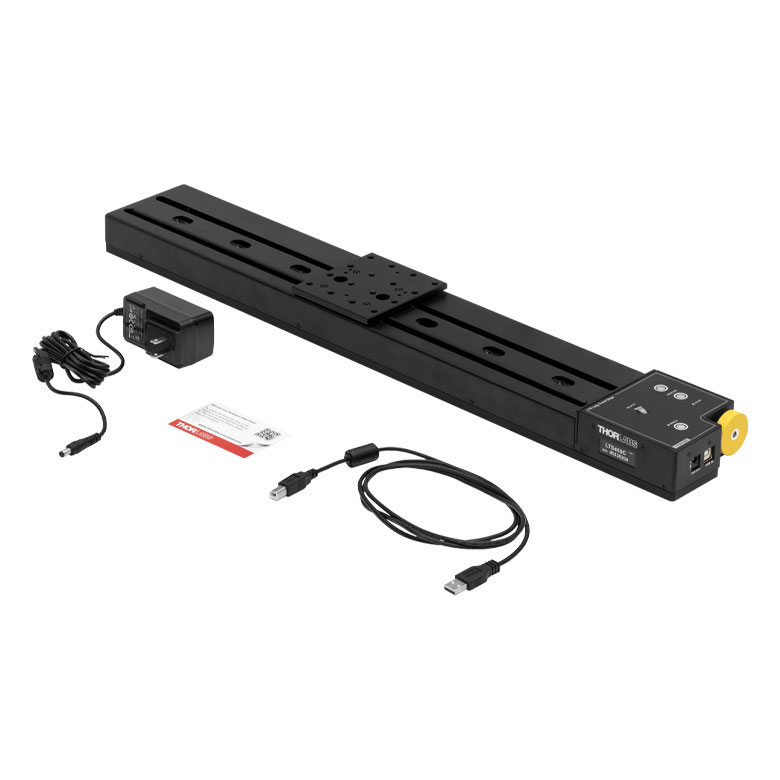
The stage offers excellent rigidity and platform parallelism. The top plate has twenty-five 1/4"-20 (M6 x 1.0) tapped holes with 0.31" (8.0 mm) depth, while the bottom plate has clearance slots that can be used to mount the stage to an optical breadboard using 1/4"-20 (M6 x 1.0) socket cap screws (not included), as shown in Figure 1.1. The unit is supplied with a location-specific power supply with an input of 100 to 240 VAC. Please connect the power supply unit (PSU) to the stage before connecting the PSU to a power outlet. A USB cable for connection to a PC is also included.
Calibration Files
Each MLJ250(/M) stage is calibrated at the factory. Calibration enables the controller to correct for any mechanical errors present in the system. Mechanical components, such as the lead screw and linkages, can be machined only within a certain tolerance. These mechanical errors result in deviations of the actual position from the commanded position. However, the deviations are repeatable and can be compensated for using the Kinesis software and included calibration files. These files are used by the Kinesis software to convert the position entered by the user into the required mechanical motion. The calibration files can be downloaded by clicking on the red Docs icon  )
)
Software Control
USB and RS232 connectivity provides simple PC-controlled operation with our Kinesis software package. The Kinesis Software features .NET controls which can be used by 3rd party developers working in the latest C#, Visual Basic, LabView or any .NET compatible languages to create custom applications. For more details the Kinesis software package, please see the Kinesis Software and Kinesis Tutorials tabs for more details.
SPECS
 Click for Details
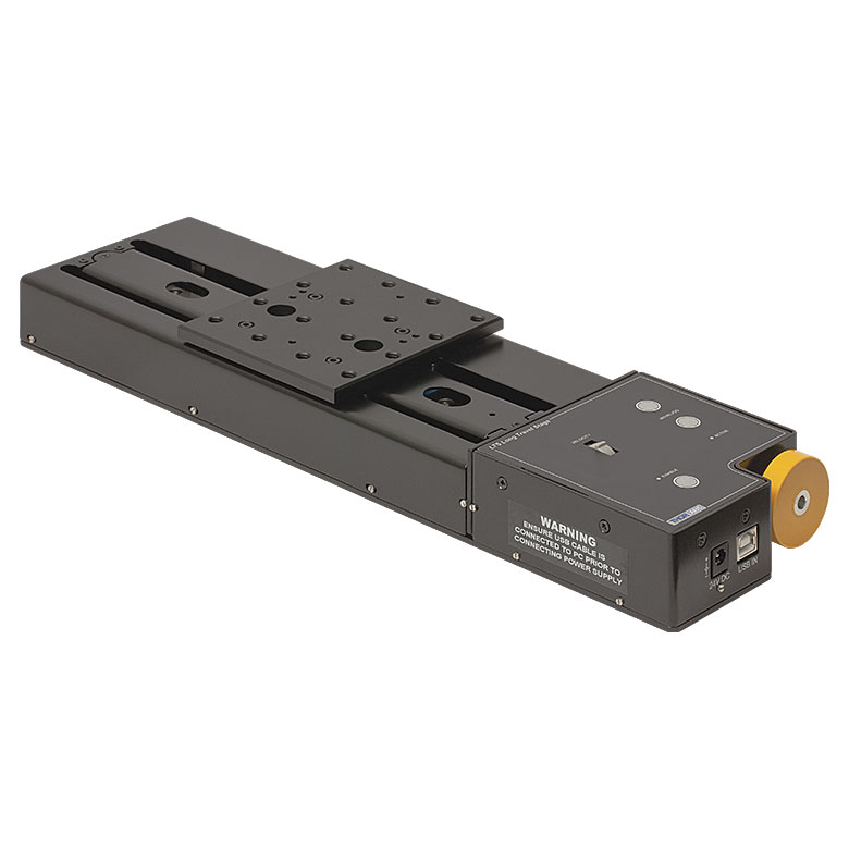
Figure 2.1 The 5.16" x 5.83" (131.0 mm x 148.0 mm) top platform of the MLJ250 has twenty-five 1/4"-20 mounting taps. The control keypad for manual control can be seen here.
 Click for Details
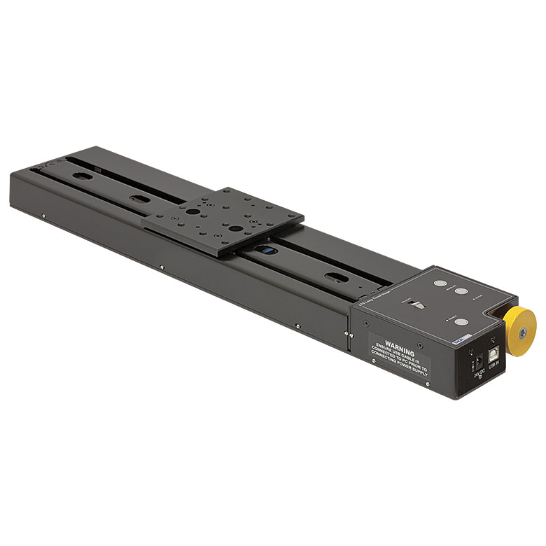
Figure 2.2 The 131.0 mm x 148.0 mm (5.16" x 5.83") top platform of the MLJ250/M has twenty-five M6 x 1.0 mounting taps. The control keypad for manual control can be seen here.
| Item # | MLJ250 | MLJ250/M | |
|---|---|---|---|
| Stage Specifications | |||
| Travel | 50 mm (1.97") | ||
| Mounting Taps | 1/4"-20, 0.31" Deep | M6 x 1.0, 8.0 mm Deep | |
| Gear Ratio | 3 to 1 (1 228 800 microsteps = 1 mm Travel) | ||
| Load (Max) | 44 lbs | 20 kg | |
| Moment Load (Max) | 5 N•m (44 in-lb) | ||
| Velocity (Max) | 3.0 mm/s at All Loads | ||
| Resolution (Theoretical) | 0.8 nm | ||
| Deck Parallelism | <150 µm Over Full Range of Travel | ||
| Unidirectional Repeatability (Software Corrected) | <10 µm | ||
| Bidirectional Repeatability (System Backlash) | <50 µm | ||
| Pitch/Roll Error Over 50 mm Travel | <500 µrad | ||
| Accuracy | <30 µm | ||
| Lead Screw Pitch | 1.0 mm | ||
| Controller Specifications | |||
| Microsteps per Full Step | 2048 | ||
| Microsteps per Revolution of Motor | 409 600 | ||
| Motor Drive Voltage | 24 V | ||
| Motor Drive Power | Up to 25 W (Peak) / 12.5 W (Avg.) | ||
| Motor Speeds | Up to 720 RPM | ||
| Motor Specifications | |||
| Step Angle | 1.8° | ||
| Step Accuracy | 5% | ||
| Rated Phase Current | 0.85 A | ||
| Phase Resistance | 5.4 Ω | ||
| Phase Inductance | 5.6 mH | ||
| Holding Torque | 20 N•cm | ||
| Detent Torque | 2.0 N•cm | ||
| Operating Temperature | -20 to 40 °C (Motor Specification Only) | ||
| Input Power Requirements | |||
| Current | 1.25 A | ||
| Voltage | 24 VDC | ||
| Power | 30 W (Peak) | ||
| General | |||
| Dimensions (W x D x H) | Extended | 5.16" x 8.53" x 4.53" | 131.0 mm x 216.7 mm x 115 mm |
| Retracted | 5.16" x 8.53" x 2.56" | 131.0 mm x 216.7 mm x 65.0 mm | |
| Mounting Platform | 5.16" x 5.83" | 131.0 mm x 148.0 mm | |
| Weight | 5.73 lbs | 2.6 kg | |
PIN DIAGRAM
| Pin | Description |
|---|---|
| 1 | Not Connected |
| 2 | Transmitted Data (Controller Input) |
| 3 | Received Data (Controller Output) |
| 4 | Not Connected |
| 5 | Ground |
| 6 | Not Connected |
| 7 | Clear to Send (CTS) Input |
| 8 | Request to Send (RTS) Output |
| 9 | Not Connected |
Computer Connections
USB Type B

USB Type B to Type A Cable Included
RS232

KINESIS SOFTWARE
Software
Kinesis Version 1.14.56
The Kinesis Software Package, which includes a GUI for control of Thorlabs' Kinesis system controllers.
Also Available:
- Firmware Update Utilities
- Communications Protocol
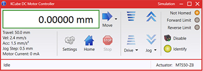
Figure 58A Kinesis GUI Screen
Thorlabs offers the Kinesis software package to drive our wide range of motion controllers. The software can be used to control devices in the Kinesis family, which covers a wide variety of motion controllers ranging from small, low-powered, single-channel drivers (such as the K-Cubes®) to high-power, multi-channel benchtop units and modular 19" rack nanopositioning systems (the MMR60x Rack System).
The Kinesis Software features .NET controls which can be used by 3rd party developers working in the latest C#, Visual Basic, LabVIEW™, or any .NET compatible languages to create custom applications. Low-level DLL libraries are included for applications not expected to use the .NET framework and APIs are included with each install. A Central Sequence Manager supports integration and synchronization of all Thorlabs motion control hardware.
By providing this common software platform, Thorlabs has ensured that users can mix and match any of our motion control devices in a single application, while only having to learn a single set of software tools. In this way, it is perfectly feasible to combine any of the controllers from single-axis to multi-axis systems and control all from a single, PC-based unified software interface.
The software package allows two methods of usage: graphical user interface (GUI) utilities for direct interaction with and control of the controllers 'out of the box', and a set of programming interfaces that allow custom-integrated positioning and alignment solutions to be easily programmed in the development language of choice.
KINESIS TUTORIALS
Thorlabs' Kinesis software features new .NET controls which can be used by third-party developers working in the latest C#, Visual Basic, LabVIEW™, or any .NET compatible languages to create custom applications.
C#
This programming language is designed to allow multiple programming paradigms, or languages, to be used, thus allowing for complex problems to be solved in an easy or efficient manner. It encompasses typing, imperative, declarative, functional, generic, object-oriented, and component-oriented programming. By providing functionality with this common software platform, Thorlabs has ensured that users can easily mix and match any of the Kinesis controllers in a single application, while only having to learn a single set of software tools. In this way, it is perfectly feasible to combine any of the controllers from the low-powered, single-axis to the high-powered, multi-axis systems and control all from a single, PC-based unified software interface.
The Kinesis System Software allows two methods of usage: graphical user interface (GUI) utilities for direct interaction and control of the controllers 'out of the box', and a set of programming interfaces that allow custom-integrated positioning and alignment solutions to be easily programmed in the development language of choice.
For a collection of example projects that can be compiled and run to demonstrate the different ways in which developers can build on the Kinesis motion control libraries, click on the links below. Please note that a separate integrated development environment (IDE) (e.g., Microsoft Visual Studio) will be required to execute the Quick Start examples. The C# example projects can be executed using the included .NET controls in the Kinesis software package (see the Kinesis Software tab for details).
 |
Click Here for the Kinesis with C# Quick Start Guide Click Here for C# Example Projects Click Here for Quick Start Device Control Examples |
|
LabVIEW
LabVIEW can be used to communicate with any Kinesis-based controller via .NET controls. In LabVIEW, you build a user interface, known as a front panel, with a set of tools and objects and then add code using graphical representations of functions to control the front panel objects. The LabVIEW tutorial, provided below, provides some information on using the .NET controls to create control GUIs for Kinesis-driven devices within LabVIEW. It includes an overview with basic information about using controllers in LabVIEW and explains the setup procedure that needs to be completed before using a LabVIEW GUI to operate a device.
 |
Click Here to View the LabVIEW Guide Click Here to View the Kinesis with LabVIEW Overview Page |
|
MOTORIZED LINEAR STAGES
Motorized Linear Translation Stages
Thorlabs' motorized linear translation stages are offered in a range of maximum travel distances, from a stage with 20 µm of piezo translation to our 600 mm direct drive stage. Many of these stages can be assembled in multi-axis configurations, providing XY or XYZ translation. For fiber coupling applications, please see our multi-axis stages, which offer finer adjustment than our standard motorized translation stages. In addition to motorized linear translation stages, we offer motorized rotation stages and goniometers. We also offer manual translation stages.
Piezo Stages
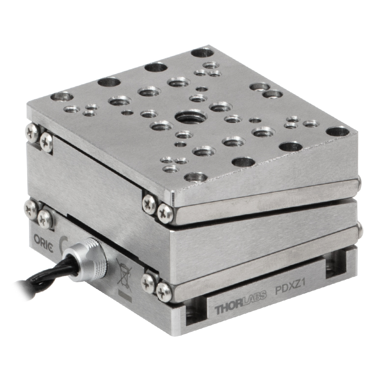
These stages incorporate piezoelectric elements in a variety of drive mechanisms. ORIC® stages incorporate piezo inertia drives that use "stick-slip" friction properties to obtain extended travel ranges. Our Nanoflex™ translation stages use standard piezo chips along with manual actuators. Elliptec® stages use resonant piezo motors to push and pull the moving platform through resonant elliptical motion. Our LPS710E z-axis stage features a mechanically amplified piezo design and includes a matched controller.
| Piezoelectric Stages | ||||||
|---|---|---|---|---|---|---|
| Product Family | ORIC® PDXZ1 Closed-Loop 4.5 mm Vertical Stage |
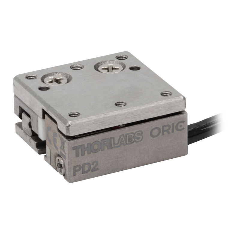
ORIC® PD2 Open-Loop 5 mm Stage |
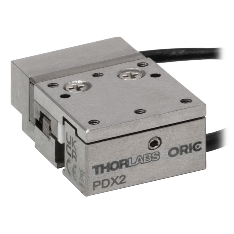
ORIC® PDX2 Closed-Loop 5 mm Stage |
ORIC® PDX4 Closed-Loop 12 mm Stage |
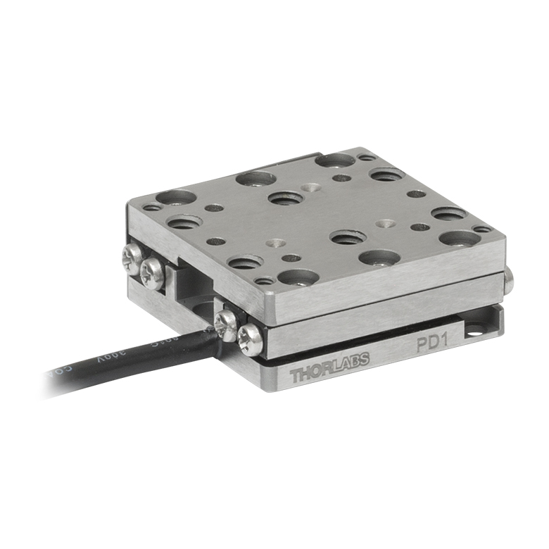
ORIC® PD1 Open-Loop 20 mm Stage |
ORIC® PD1D Open-Loop 20 mm Monolithic XY Stage |
| Click Photo to Enlarge |
 |
 |
 |
 |
 |
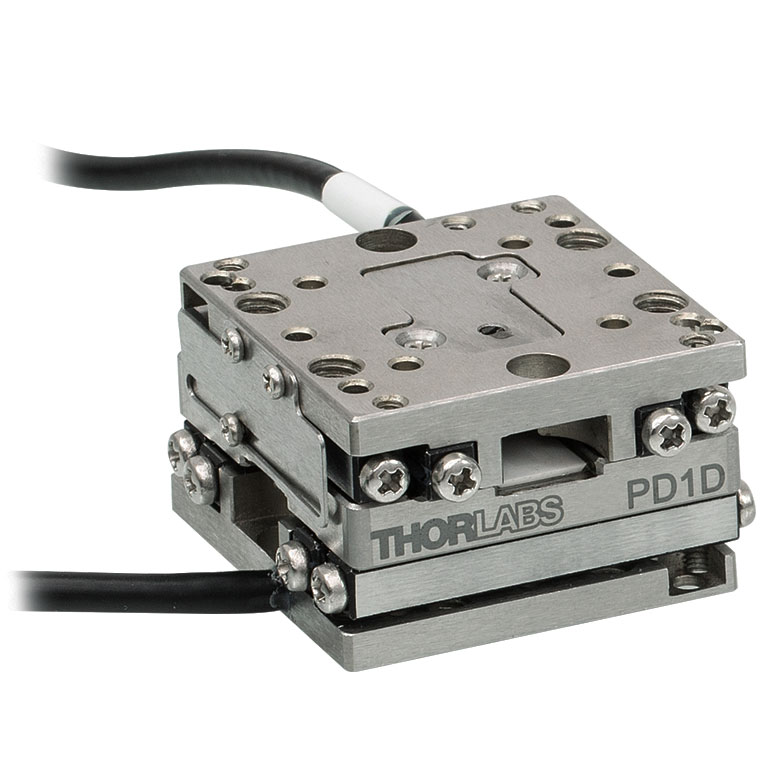 |
| Travel | 4.5 mm | 5 mm | 12 mm | 20 mm | ||
| Speed | 1 mm/s (Typ.)a | 10 mm/s (Typ. Max)b | 8 mm/s (Typ.)c | 15 mm/s (Typ.)a,c | 3 mm/s (Typ. Max)d | |
| Drive Type | Piezoelectric Inertia Drive | |||||
| Possible Axis Configurations | Z | X, XY, XYZ | XY, XYZ | |||
| Mounting Surface Size |
45.0 mm x 42.0 mm | 13.0 mm x 13.0 mm | 13.0 mm x 23.0 mm | 30.0 mm x 30.0 mm | ||
| Additional Details | ||||||
| Piezoelectric Stages | ||||||
|---|---|---|---|---|---|---|
| Product Family | ORIC® PDX1 Closed-Loop 20 mm Stage |
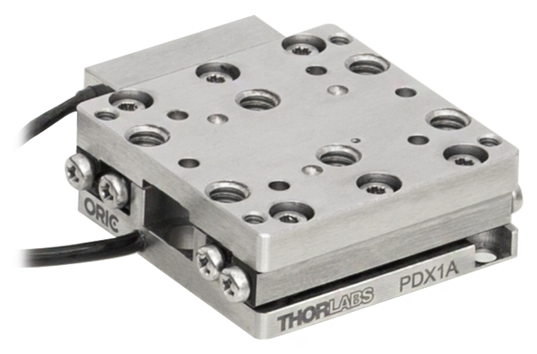
ORIC® PDX1A Closed-Loop 20 mm Stage Low-Profile |
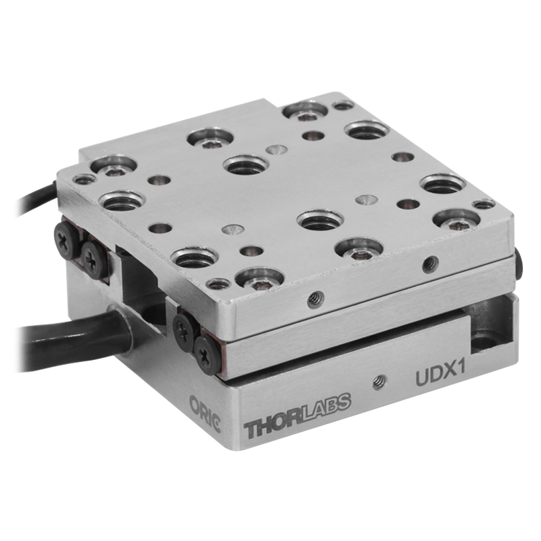
ORIC® UDX1 Ultrasonic Closed-Loop 20 mm Stage |
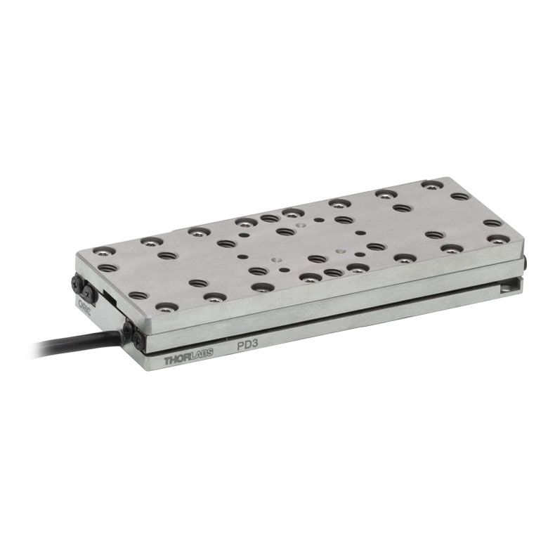
ORIC® PD3 Open-Loop 50 mm Stage |
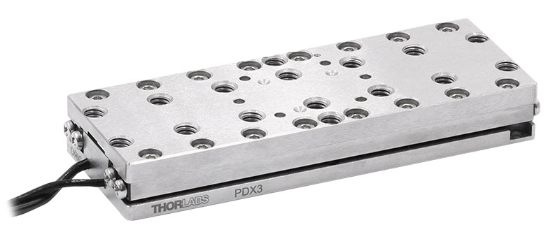
ORIC® PDX3 Closed-Loop 50 mm Stage |
|
| Click Photo to Enlarge |
 |
 |
 |
 |
 |
|
| Travel | 20 mm | 50 mm | ||||
| Speed | 20 mm/s (Typ. Max)a | 10 mm/s (Typ.)b | 100 mm/s (Typ. Max)c | 10 mm/sd | 10 mm/s (Typ. Max)b | |
| Drive Type | Piezoelectric Inertia Drive | Ultrasonic Piezoelectric Drive | Piezoelectric Inertia Drive | |||
| Possible Axis Configurations | X, XY, XYZ | |||||
| Mounting Surface Size |
30.0 mm x 30.0 mm | 80.0 mm x 30.0 mm | ||||
| Additional Details | ||||||
| Piezoelectric Stages | |||||||
|---|---|---|---|---|---|---|---|
| Product Family | Nanoflex™ 20 µm Stage with 5 mm Actuator |
Nanoflex™ 25 µm Stage with 1.5 mm Actuator |
Compact Modular XRN25X 25 mm Stage |
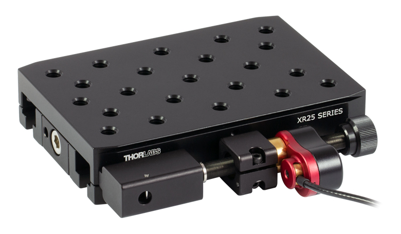
Modular XR25X 25 mm Stage |
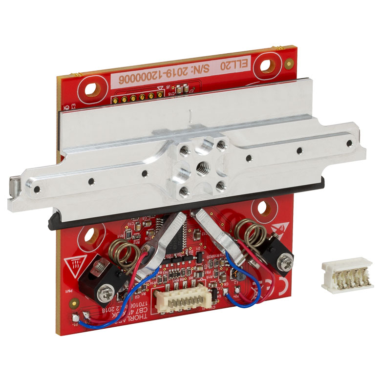
Elliptec® 28 mm Stage | Elliptec® 60 mm Stage | LPS710E 1.1 mm Vertical Stage |
| Click Photo to Enlarge |
 |
 |
 |
 |
 |
 |
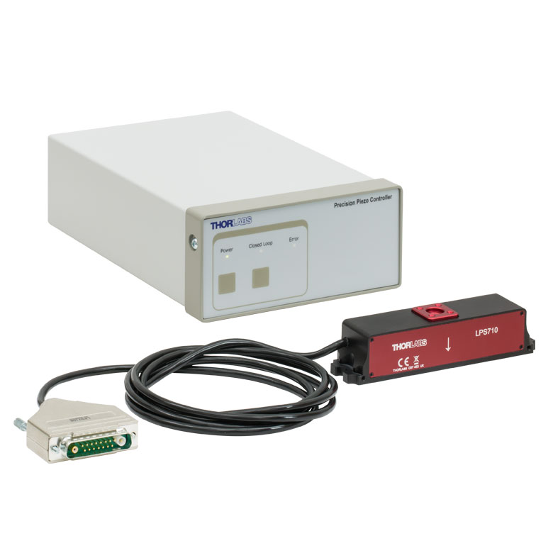 |
| Travel | 20 µm + 5 mm Manual | 25 µm + 1.5 mm Manual | 25 mm | 28 mm | 60.0 mm | 1.1 mm | |
| Maximum Velocity | - | ≤3.6 mm/mina | 180 mm/s | 90 mm/s | - | ||
| Drive Type | Piezo with Manual Actuator | Piezoelectric Inertia Drive | Resonant Piezoelectric Motor | Amplified Piezo | |||
| Possible Axis Configurations | X, XY, XYZ | X, XY, YZ, XZ, XYZ | X | Z | |||
| Mounting Surface Size | 75 mm x 75 mm | 30 mm x 30 mm | 85.0 mm x 50.7 mm | 110.0 mm x 75.7 mm | 15 mm x 15 mm | 21 mm x 21 mm | |
| Additional Details | |||||||
Stepper Motor Stages
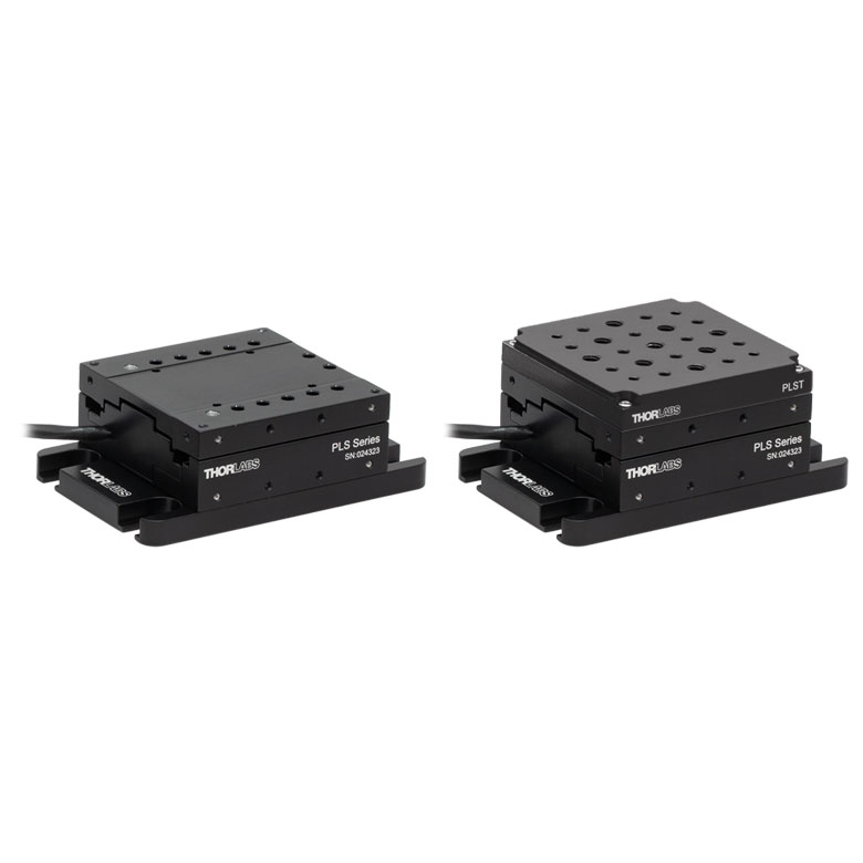
These translation stages feature removable or integrated stepper motors and long travel ranges up to 300 mm. Many of these stages either have integrated multi-axis capability (PLSXY) or can be assembled into multi-axis configurations (PLSX, LNR Series, NRT Series, and LTS Series stages). The MLJ150 stage also offers high load capacity vertical translation.
| Stepper Motor Stages | |||||
|---|---|---|---|---|---|
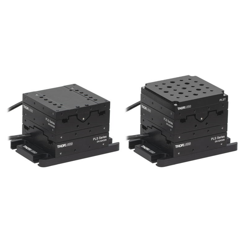
| Product Family | PLSX with and without PLST(/M) Top Plate 1" Stage |
PLSXY with and without PLST(/M) Top Plate 1" Stage |
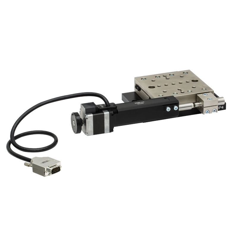
LNR Series 25 mm Stage |
LNR Series 50 mm Stage |
|
| Click Photo to Enlarge |
 |
 |
 |
 |
|
| Travel | 1" | 25 mm | 50 mm | ||
| Maximum Velocity | 7.0 mm/s | 2.0 mm/s | 50 mm/s | ||
| Possible Axis Configurations |
X, XY | X, XY, XYZ | X, XY, XYZ | ||
| Mounting Surface Size |
3" x 3" | 60 mm x 60 mm | 100 mm x 100 mm | ||
| Additional Details | |||||
| Stepper Motor Stages | |||||||
|---|---|---|---|---|---|---|---|
| Product Family | NRT Series 100 mm Stage |
NRT Series 150 mm Stage |
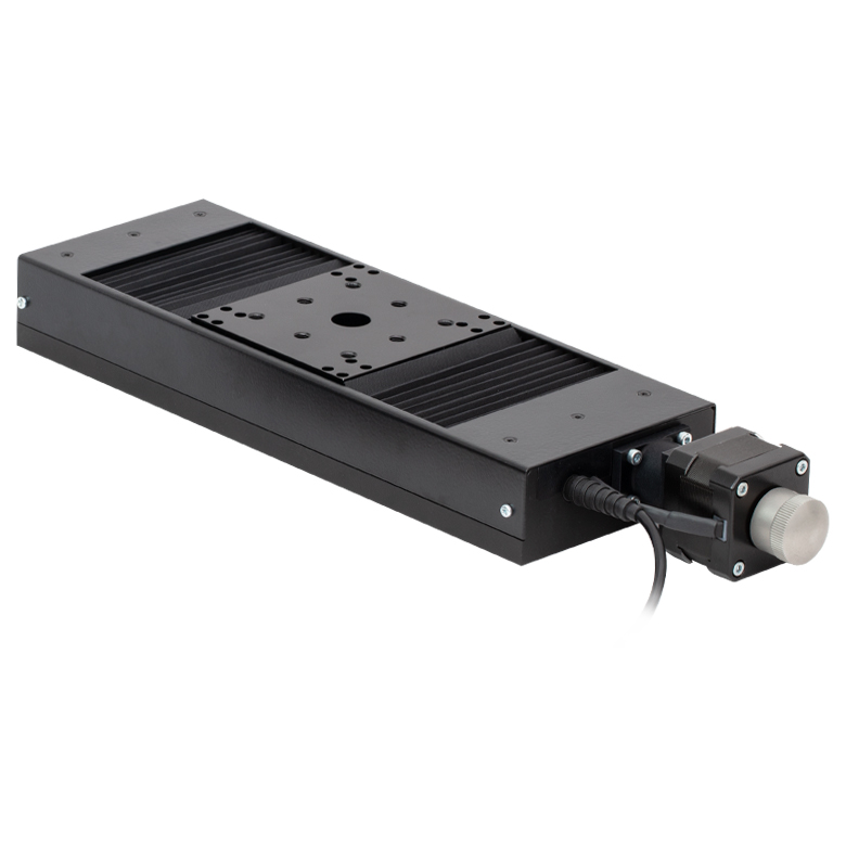
LTS Series 150 mm Stage |
LTS Series 300 mm Stage |
LTS Series 450 mm Stage |
MLJ250 50 mm Vertical Stage |
|
| Click Photo to Enlarge |
 |
 |
 |
 |
 |
 |
|
| Travel | 100 mm | 150 mm | 150 mm | 300 mm | 400 mm | 50 mm | |
| Maximum Velocity | 30 mm/s | 50 mm/s | 3.0 mm/s | ||||
| Possible Axis Configurations |
X, XY, XYZ | X, XY, XYZ | X, XY | Z | |||
| Mounting Surface Size |
84 mm x 84 mm | 100 mm x 90 mm | 148 mm x 131 mm | ||||
| Additional Details | |||||||
DC Servo Motor Stages
Thorlabs offers linear translation stages with removable or integrated DC servo motors. These stages feature low profiles and many can be assembled in multi-axis configurations.
| DC Servo Motor Stages | ||||
|---|---|---|---|---|
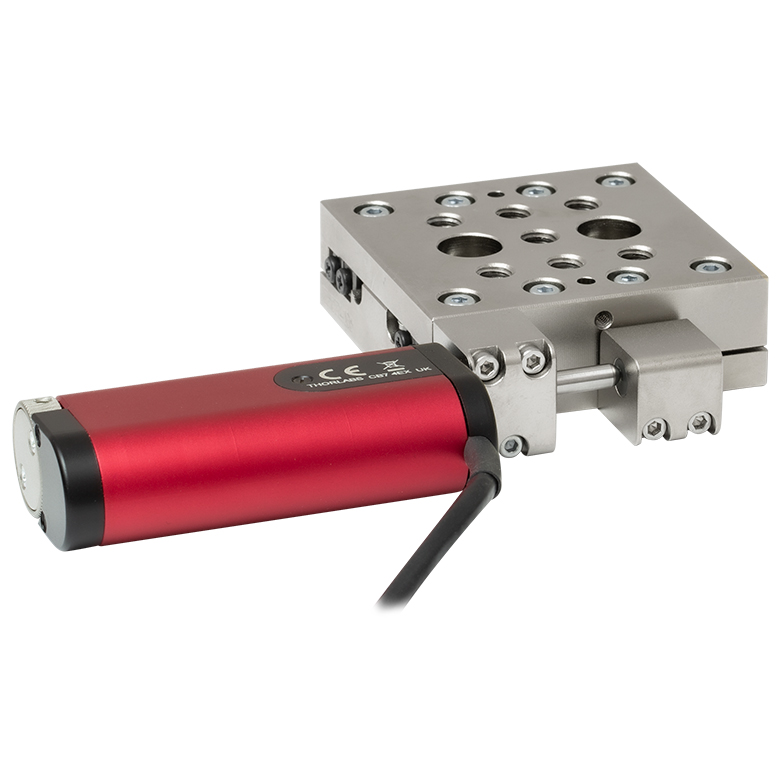
| Product Family | MT Series 12 mm Stages |
PT Series 25 mm Stages |
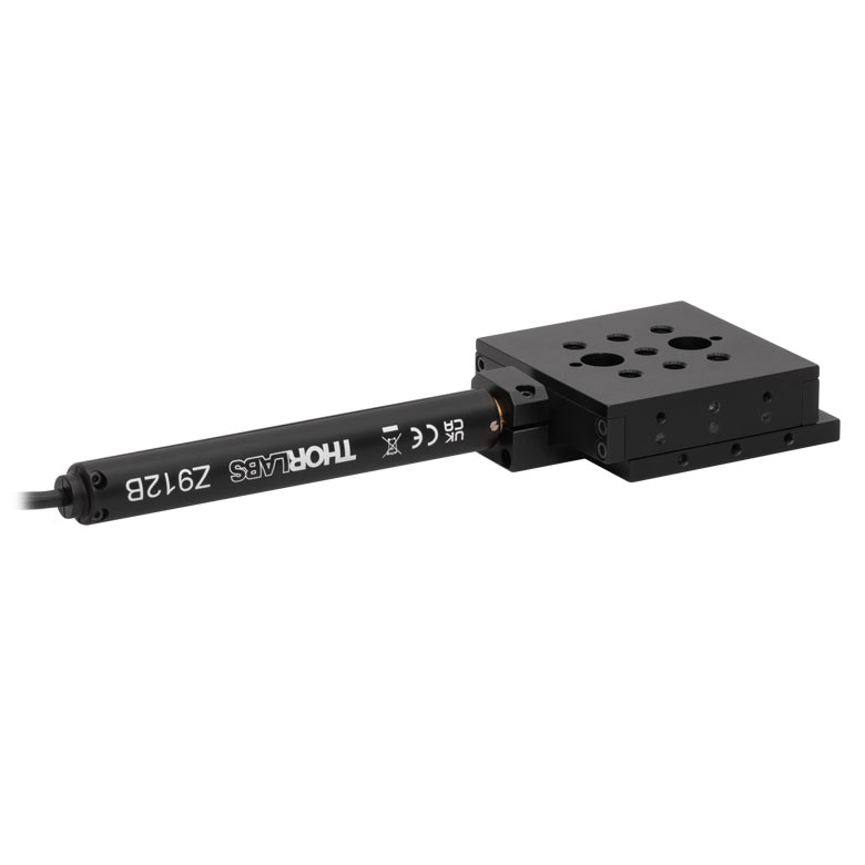
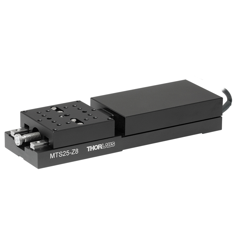
MTS Series 25 mm Stage |
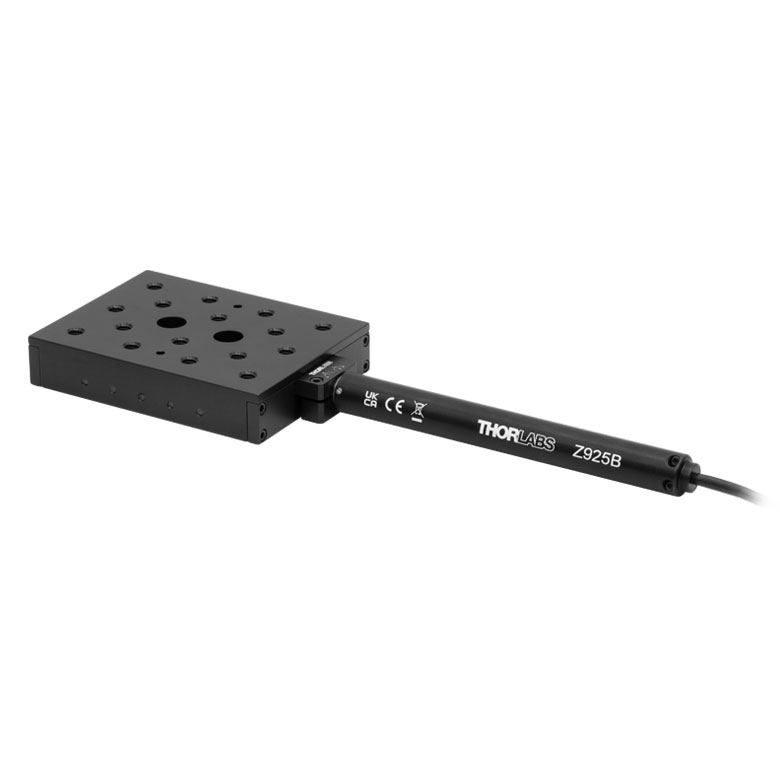
MTS Series 50 mm Stage |
| Click Photo to Enlarge |
 |
 |
 |
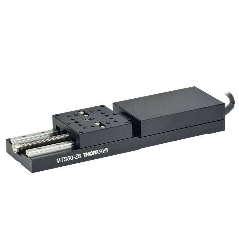 |
| Travel | 12 mm | 25 mm | 25 mm | 50 mm |
| Maximum Velocity | 2.6 mm/s | 2.4 mm/s | ||
| Possible Axis Configurations | X, XY, XYZ | X, XY, XYZ | ||
| Mounting Surface Size |
61 mm x 61 mm | 101.6 mm x 76.2 mm | 43 mm x 43 mm | |
| Additional Details | ||||
| DC Servo Motor Stages | ||||
|---|---|---|---|---|
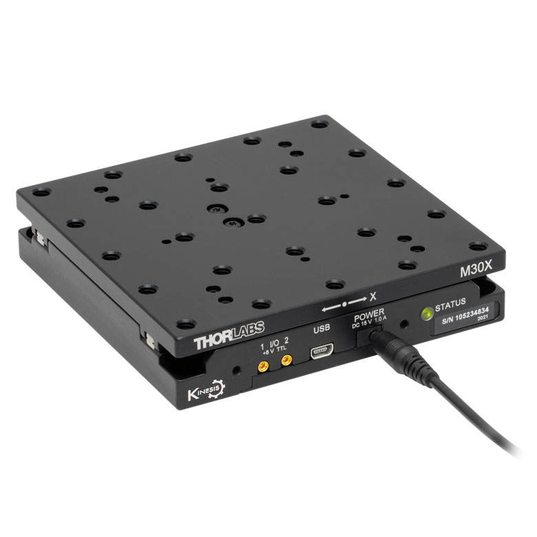
| Product Family | M30 Series 30 mm Stage |
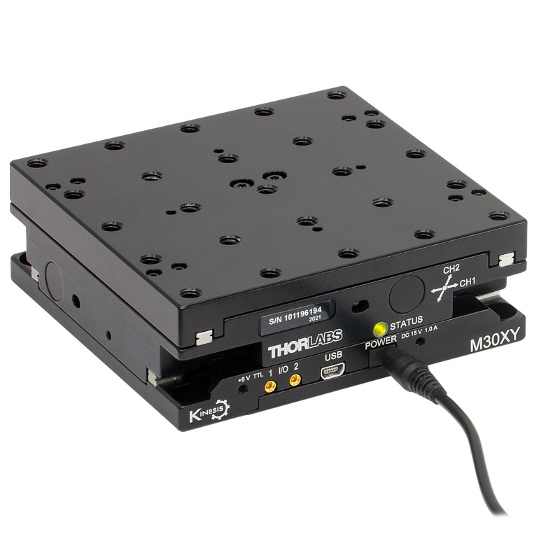
M30 Series 30 mm Monolithic XY Stage |
M150 Series 150 mm XY Stage |
KVS30 30 mm Vertical Stage |
| Click Photo to Enlarge |
 |
 |
 |
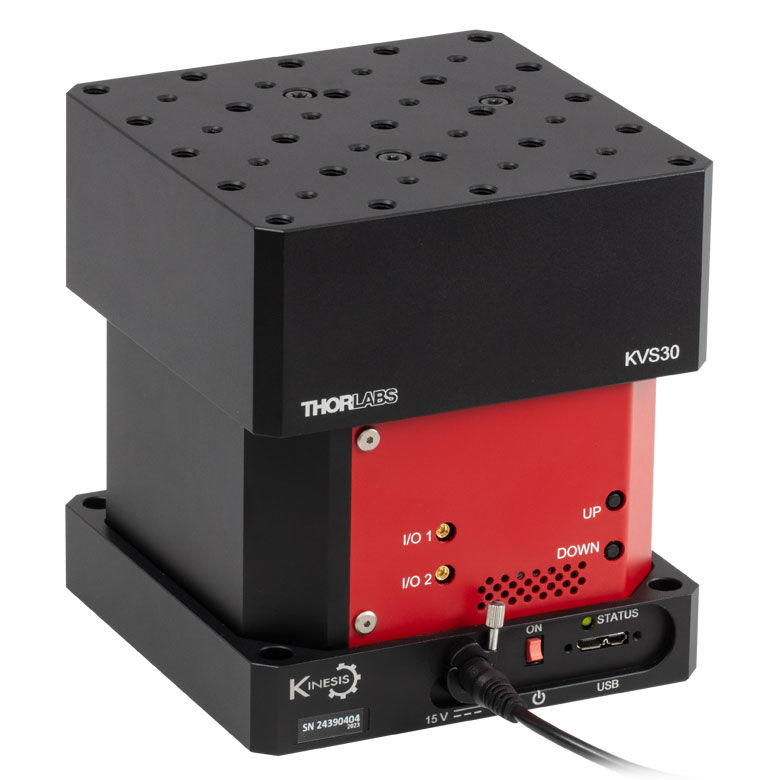 |
| Travel | 30 mm | 150 mm | 30 mm | |
| Maximum Velocity | 2.4 mm/s | X-Axis: 170 mm/s Y-Axis: 230 mm/s |
8.0 mm/s | |
| Possible Axis Configurations | X, Z | XY, XZ | XY | Z |
| Mounting Surface Size |
115 mm x 115 mm | 272.4 mm x 272.4 mm | 116.2 mm x 116.2 mm | |
| Additional Details | ||||
Direct Drive Stages
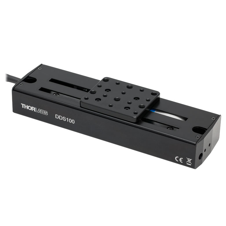
These low-profile stages feature integrated brushless DC servo motors for high speed translation with zero backlash. When no power is applied, the platforms of these stages have very little inertia and are virtually free running. Hence these stages may not be suitable for applications where the stage's platform needs to remain in a set position when the power is off. We do not recommend mounting these stages vertically.
| Direct Drive Stages | |||||
|---|---|---|---|---|---|
| Product Family | DDS Series 50 mm Stage |
DDS Series 100 mm Stage |
DDS Series 220 mm Stage |
DDS Series 300 mm Stage |
DDS Series 600 mm Stage |
| Click Photo to Enlarge |
 |
 |
 |
 |
 |
| Travel | 50 mm | 100 mm | 220 mm | 300 mm | 600 mm |
| Maximum Velocity | 500 mm/s | 300 mm/s | 400 mm/s | 400 mm/s | |
| Possible Axis Configurations | X, XY | X, XY | X | X | |
| Mounting Surface Size | 60 mm x 52 mm | 88 mm x 88 mm | 120 mm x 120 mm | ||
| Additional Details | |||||
Motorized High-Load Vertical Translation Stage
Part Number | Description | Price | Availability |
|---|---|---|---|
MLJ250/M | Customer Inspired! Motorized High-Load Vertical Translation Stage, 50 mm Travel, M6 Taps | $4,212.80 | In Stock Overseas |
MLJ250 | Customer Inspired! Motorized High-Load Vertical Translation Stage, 50 mm Travel, 1/4"-20 Taps | $4,212.80 | In Stock Overseas |