 Products Home / Motorized Stages / Motorized Linear Stages / Long Travel Linear Motorized Stages (>100 mm) / 300 mm Linear Translation Stage with Integrated Controller, Stepper Motor
300 mm Linear Translation Stage with Integrated Controller, Stepper Motor
- Integrated Controller with Keypad and Remote USB Control
- Stackable in XY, XZ, and XYZ Configurations
- Calibrated On-Axis Accuracy of <±5 µm
- Horizontal Load Capacity of 15 kg (33.1 lbs)
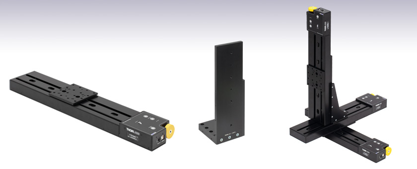
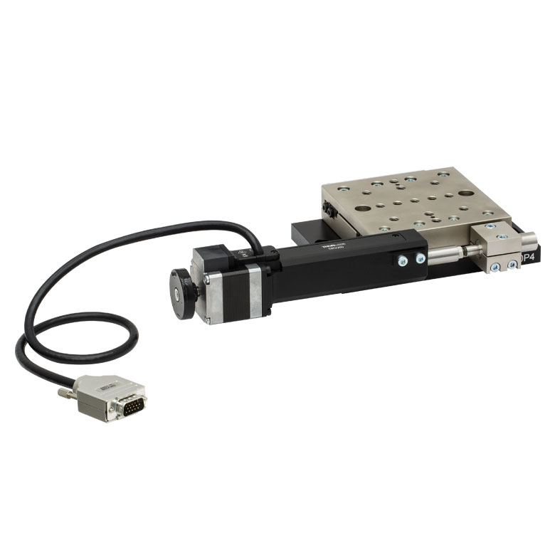
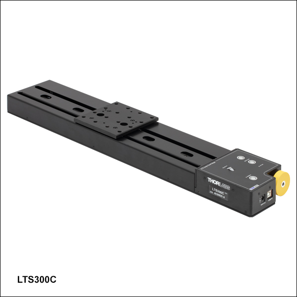
LTS300C
300 mm Translation Stage
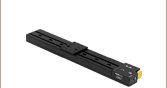
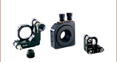
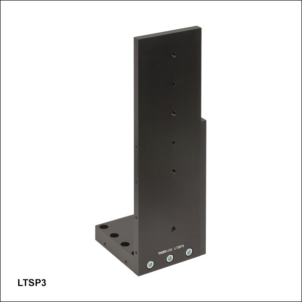
LTSP3
Right-Angle Bracket
Application Idea
Three LTS300C Stages in
XYZ Configuration, Using an
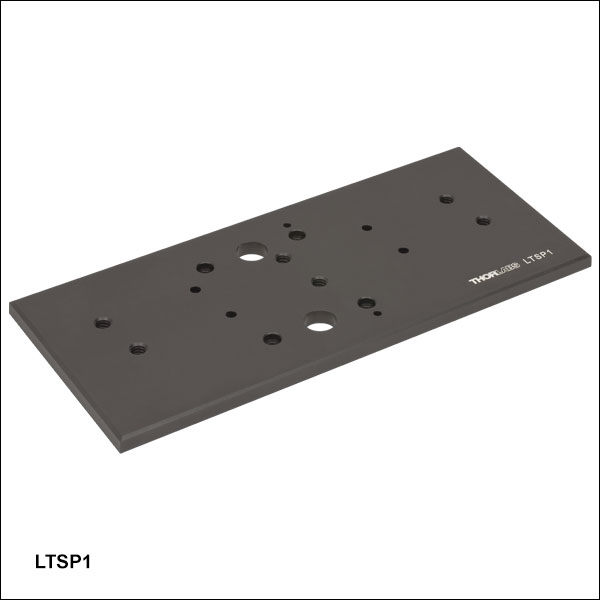
LTSP1 XY Adapter Plate and
LTSP3 Right-Angle Bracket


Please Wait
| Key Specificationsa | |
|---|---|
| Travel Range | 300 mm (11.8") |
| Horizontal Velocity (Max) | 50 mm/s |
| Vertical Velocity (Max) | 3 mm/s |
| Minimum Achievable Incremental Movementb |
0.1 µm |
| Calibrated On-Axis Accuracyc | <±5 µm |
| Bidirectional Repeatabilityd | <±2 µm |
| Backlashe | 2 µm |
| Load Capacity (Max) - Stage Mounted Horizontally |
15 kg (33.1 lbs) |
| Load Capacity (Max) - Stage Mounted Vertically |
4 kg (8.8 lbs) |
| Actuator Type | Stepper Motor |
| Included USB Cable Length | 1.5 m (4.9 ft) |
Features
- 300 mm Travel Range
- Integrated Stepper Motor Controller
- Control via Manual Keypad or Remote PC
- Load Capacity
- Horizontally Mounted: 15 kg (33.1 lbs)
- Vertically Mounted: 4 kg (8.8 lbs)
- Maximum Velocity of 50 mm/s
- Bidirectional Repeatability of <±2 µm
- XY, XZ, and XYZ Configurable
- 1/4"-20 or M6 Tapped Holes for Mounting Standard Optomechanics
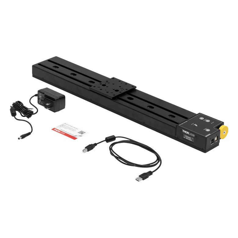
- Power Supply Included
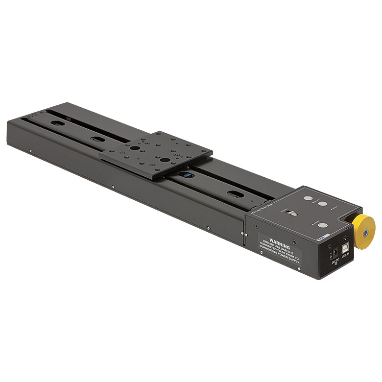
Thorlabs' LTS300C(/M) Linear Translation Stage with Integrated Controller is optimized for applications requiring high load capacity and high resolution, such as measurement and inspection. It provides 300 mm of linear travel for loads as great as 15 kg (33.1 lbs) when mounted horizontally and 4 kg (8.8 lbs) when mounted vertically. Each stage features a calibrated on-axis accuracy of <±5 µm when the unit-specific calibration files are used with the Thorlabs Kinesis software. Due to the stepper motor design, the platform position remains fixed when no power is supplied to the stage, unlike with DC servo motor translation stages.
Click to Enlarge
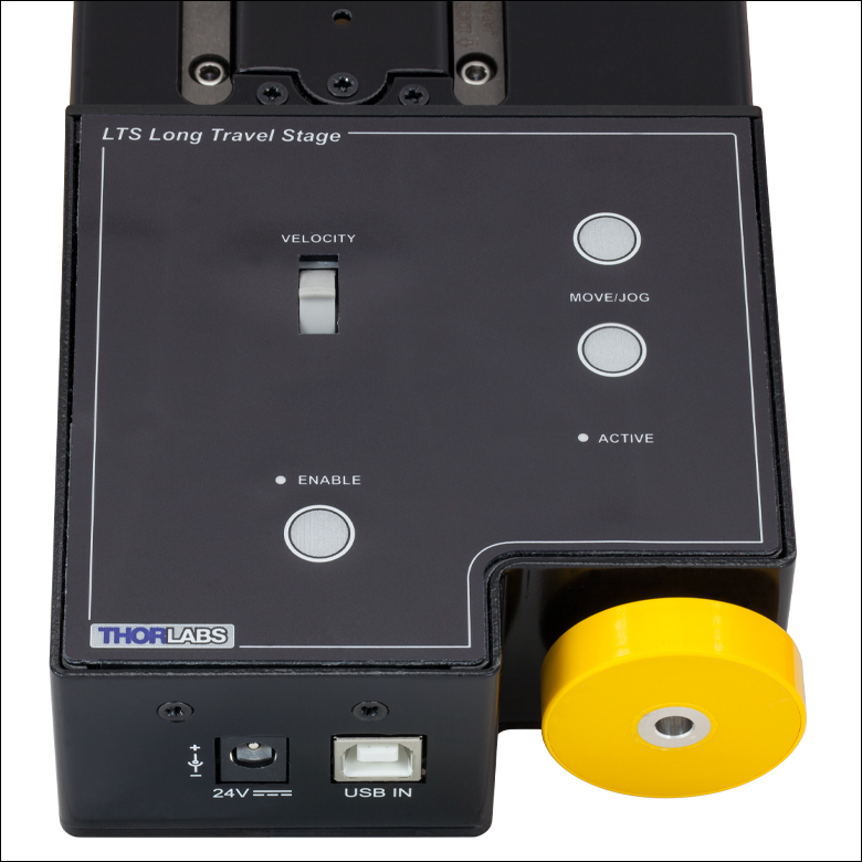
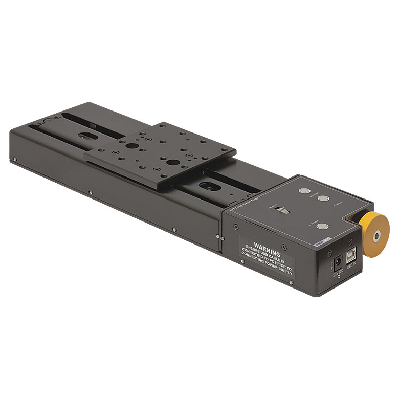
Figure 1.1 Integrated Controller with Manual and Remote PC Control
| Motorized Linear Long-Travel Stages | |
|---|---|
| 100 mm | Stepper |
| DC Servo | |
| 150 mm | Stepper |
| Stepper with Integrated Controller | |
| 220 mm | DC Servo |
| 300 mm | Stepper with Integrated Controller |
| DC Servo | |
| 450 mm | Stepper with Integrated Controller |
| 600 mm | DC Servo |
| Optical Delay Line Kits | |
| Other Translation Stages | |
The LTS300C(/M) stage features an integrated electronic controller that can be controlled remotely using a PC or manually via the buttons and velocity potentiometer on the control keypad (see Figure 1.1). Parameter settings can be adjusted on the PC and stored in non-volatile memory within the unit itself. When the unit is powered up, these settings are applied automatically. This is particularly useful when the stage is being used manually in the absence of a PC and USB link.
The stage is lightweight, compact, and robust with high performance over the full travel range. The heavy-duty aluminum construction and 40.5 mm moving platform height makes this stage ideal for applications where space is limited. Integrated magnetic limit switches allow homing and overdrive protection in both directions. A precision-ground lead screw delivers smooth, virtually noise-free movement. The power supply provided with the stage operates with 90 - 264 VAC input voltages (47 - 63 Hz) and is shipped with a location-specific power cord.
Thorlabs also offers the LTS150C(/M) Linear Translation Stage with Integrated Controller, which features 150 mm of travel.
Calibration Files
Each LTS300C(/M) Linear Translation Stage is calibrated during manufacturing. Calibration enables the controller to correct for any mechanical errors present in the system. Mechanical components, such as the lead screw and linkages, can be machined only within a certain tolerance. These mechanical errors result in deviations of the actual position from the commanded position. However, the deviations are repeatable and can be compensated for using the Kinesis software and included calibration files. These files are used by the software to convert the position entered by the user into the required mechanical motion. The calibration files can be downloaded by clicking on the red Docs icon  )
)
The use of calibration files is optional. Without them, the repeatability and resolution of the stage are unaffected, but no compensations are made to enhance the accuracy. Each stage is calibrated at the factory, giving a typical on-axis accuracy of 47 µm without the use of the calibration files.
Stage Combinations
If an XY configuration is desired, any combination of LTS300C(/M) and LTS150C(/M) Linear Positioning Stages (the latter features a 150 mm travel range) can be mounted atop one another using the LTSP1(/M) XY Adapter Plate (sold below). XZ and XYZ configurations are possible using our LTSP3(/M) Z-Axis Bracket, which orients an LTS300C(/M) stage in the vertical plane. Please note that stages and adapters with imperial or metric taps are only compatible with other stages and adapters featuring the same thread standards.
Software
Thorlabs offers the Kinesis® software package to drive our wide range of motion controllers, including our multi-channel controllers, rack-based controller, and smaller, optical-table-mountable K-Cube® controllers. This single unified software offering allows seamless mixing of the LTS150C(/M) stages with any benchtop, tabletop, or rack-based controllers.
| Stage Specifications | ||
|---|---|---|
| Translation | ||
| Travel Range | 300 mm (11.8") | |
| Bidirectional Repeatability | <±2 µm | |
| Backlash | 2 µm | |
| Maximum Velocitya | 50 mm/s Horizontal, 3 mm/s Vertical | |
| Velocity Stability | ±1 mm/s | |
| Maximum Accelerationa | 50 mm/s2 Horizontal, 5 mm/s2 Vertical | |
| Accuracy | ||
| Min Achievable Incremental Movementb | 100 nm | |
| Min Repeatable Incremental Movementc | 4 µm | |
| Calibrated On-Axis Accuracy | <±5 µm | |
| Max Percentage Accuracyd | 0.12% | |
| Home Location Accuracy | ±0.6 µm | |
| Pitche | <0.022° (384 µrad) | |
| Yawe | <0.06° (1047 µrad) | |
| Load Capacity | ||
| Horizontal Load Capacity | Max: 15 kg (33.1 lbs) Recommended: <12 kg (26.5 lbs) |
|
| Vertical Load Capacity | Max: 4 kg (8.8 lbs) | |
| General | ||
| Included USB Cable Length | 1.5 m (4.9 ft) | |
| Weight | 3.0 kg (6.61 lbs) | |
| Dimensions (W x D x H) | 100.0 mm x 500.0 mm x 40.5 mm (3.94" x 19.69" x 1.59") |
|
| Electrical Specifications | |
|---|---|
| Motor Specifications | |
| Step Angle | 1.8° (50 Poles and ±2 Phases for 360° Divided by 200) |
| Step Accuracy | 5% |
| Rated Phase Current | 0.85 A |
| Phase Resistance | 5.4 Ω |
| Phase Inductance | 5.6 mH |
| Holding Torque | 20 N•cm |
| Detent Torque | 2.0 N•cm |
| Operating Temperature | -20 to 40 °C (Motor Specification Only) |
| Controller Specifications | |
| Microsteps per Full Step | 2048 |
| Microsteps per Revolution of Motor | 409,600 (for 200 Step Motor) |
| Motor Drive Voltage | 24 V |
| Motor Drive Power | 12.5 W (Avg.) Up to 25 W (Peak) |
| Motor Speeds | Up to 3000 RPM (200 Full Step Motor) |
| Input Power Requirements | |
| Voltage | 24 VDC |
| Power | 25 W (Peak) |
| Power Supply Requirements | 90 - 264 VAC (47 - 63 Hz) |
Notes
Computer Connection
USB Type B

2 m (6.5 ft) USB Type B to Type A Cable Included
Software
Kinesis Version 1.14.58
The Kinesis Software Package, which includes a GUI for control of Thorlabs' Kinesis system controllers.
Also Available:
- Firmware Update Utilities
- Communications Protocol
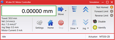
Figure 58A Kinesis GUI Screen
Thorlabs offers the Kinesis software package to drive our wide range of motion controllers. The software can be used to control devices in the Kinesis family, which covers a wide variety of motion controllers ranging from small, low-powered, single-channel drivers (such as the K-Cubes®) to high-power, multi-channel benchtop units and modular 19" rack nanopositioning systems (the MMR60x Rack System).
The Kinesis Software features .NET controls which can be used by 3rd party developers working in the latest C#, Visual Basic, LabVIEW™, or any .NET compatible languages to create custom applications. Low-level DLL libraries are included for applications not expected to use the .NET framework and APIs are included with each install. A Central Sequence Manager supports integration and synchronization of all Thorlabs motion control hardware.
By providing this common software platform, Thorlabs has ensured that users can mix and match any of our motion control devices in a single application, while only having to learn a single set of software tools. In this way, it is perfectly feasible to combine any of the controllers from single-axis to multi-axis systems and control all from a single, PC-based unified software interface.
The software package allows two methods of usage: graphical user interface (GUI) utilities for direct interaction with and control of the controllers 'out of the box', and a set of programming interfaces that allow custom-integrated positioning and alignment solutions to be easily programmed in the development language of choice.
| Posted Comments: | |
Su Peilei
(posted 2025-07-21 12:19:47.807) Hi, When I was using the LTS300C/M, I encountered a problem of the table getting stuck. When the velocity and acceleration set by the displacement table are high, when the LTS300C/M reaches a certain speed, it will get stuck and the motor will still make sound. For example, when setting the velocity to 14 and the acceleration to 20, if the LTS300C/M reaches 14 or does not reach 14, the LTS300C/M will get stuck. When the speed is set to 10 and the acceleration is 20, the LTS300C/M can travel the entire 300mm, but there is still a certain possibility of getting stuck. When the speed is set to 5 and the acceleration is 20, the LTS300C/M will not get stuck. In addition, I modified the velocity strategy from trapezoid to SCurve and set the Bow index to 1. At this time, the velocity is set to 50 and the acceleration is set to 50. The displacement platform will not get stuck and can complete the entire journey. However, when the Bow index is changed to 2, the LTS300C/M will still get stuck. In summary, what is the reason for this problem and is it necessary to send it for repair? I am eager to receive your reply. Thank you! dnewnham
(posted 2025-07-24 07:19:06.0) Thank you for your inquiry, I will reach out to you directly to discuss your application and next steps to be taken. Richard Harris
(posted 2023-06-28 11:49:14.65) I am looking at the LTS300C and would like to know if this has an optical encoder to measure distance moved? do'neill
(posted 2023-07-04 10:06:14.0) Response from Daniel at Thorlabs. The LTS300C does not have an optical encoder, the stage counts steps from the home position. Ahmad Rafsanjani
(posted 2023-01-30 08:11:47.347) Hi there,
We have a LTS300 linear stage and we would like to control it from MATLAB.
We found some examples on the web for other models but we could not adjust it to LTS300. Can you please provide a MATLAB code for this purpose?
Thanks,
Ahmad Rafsanjani
Associate Prof, SDU Biorobotics, Denmark do'neill
(posted 2023-01-30 12:16:29.0) Response from Daniel at Thorlabs. Thank you for your feedback, we have reached out to you directly to provide this script. user
(posted 2022-09-19 17:10:36.03) We are using LTS300/M and found a problem with parameter "steps per rev" in the software APT User. When the "steps per rev" was set to 800 (the default value is 200), the real motion distance of the stage is 4 times that of setting value. For example, a moving of 5 mm results in a real moving of 20 mm. DJayasuriya
(posted 2022-09-27 04:15:32.0) Thank you for your feedback, we have reached out to you directly to resolve the issue. Zahra Navabi
(posted 2022-07-29 08:01:46.077) Hi,
I purchased the LTS300/M stage about 2 months ago. The actuator makes a very loud noise when it gets to about 100 mm distance. Reducing the movement speed was helping at first, but now it's always very loud when it gets there. I have tried lubricating the lead screw, but it didn't help. I would be thankful if you could help me with that. I really need the actuator to be in my system, and it will almost shut down the project if I need to send it back. DJayasuriya
(posted 2022-08-01 08:17:59.0) Thank you for your inquiry. we will get in touch with you directly to resolve this. user
(posted 2022-06-23 12:59:30.963) Hello,
Two questions:
it is possible to operate the stage inverted ? Means, can the items to be moved hang down from the stage ? If so, what would be the maximum weight ?
Can you offer a LAN - interface for computer control ?
Thanks
Stephen cwright
(posted 2022-06-24 04:41:17.0) Response from Charles at Thorlabs: Thank you for your query. Unfortunately we can not provide this device with an ethernet connection. While we have not characterised a maximum load for this stage when used inverted we will reach out to discuss your application and assess whether it will meet your needs. user
(posted 2022-06-09 08:48:57.93) Is it possible tp program these devices in Kinesis to move in a circle motion repeatedly (with increasing or decreasing radius)? If so, do you happen to have such sequence programmed already that you could send me?
Thanks cwright
(posted 2022-06-09 11:02:39.0) Response from Charles at Thorlabs: Thank you for contacting us. These devices are not suited to this application. You could create an array of positions for both an X and Y axis, which would move the top plate to positions on a circumference but unfortunately you cannot command the LTS to move between two positions with a sinusoidal varying velocity, which would be required on both axes to traverse a constant circle. Anton Bäck
(posted 2022-04-26 11:50:46.207) Hello Thorlabs,
I am working with your LTS300 device to work together with our API in .NET but I have a small issue I was hoping you could assist me with. On a few occasions, the motor has initiated an "Offset" sequence during an exception leading to the home position being transferred to the other side of the ledge and not close to the motor. While this has only happened twice and I've tried to re-trigger this issue so that I can develop an align function to prevent this, somehow it doesn't want to reset it. Do you have any idea on how to trigger this issue so that it is troubleshootable or if their is any fix to this issue which you could provide me with? Thanks in advance, Anton Bäck do'neill
(posted 2025-02-21 07:33:53.0) Thank you for reaching out. We have reached out directly to help support your troubleshooting. yamit geron
(posted 2022-03-16 22:17:36.127) Greetings ,
I got the product and power supply but I do not understand how to assemble it, came in two parts.
I would love guidance.
Thanks Yamit Geron DJayasuriya
(posted 2022-03-17 07:46:08.0) Thank you for your inquiry. On the LTS next to the USB port you should be able to plug the power supply in. Alexander Dumont
(posted 2021-06-16 10:58:38.477) What power unit do we need for this device. I have a LTS300, with no power supply, and I would like to know what power supply is needed.
Thanks
Alex YLohia
(posted 2021-08-27 02:38:40.0) The power requirements are listed on the "Specs" tab on the product page. We do not recommend using a third-party PSU as we cannot guarantee performance. We can, however, supply you a replacement component PSU if interested. Mikael Malmstrom
(posted 2021-06-10 09:43:12.833) I'm trying to communicate with my LTS300/M with Matlab but I'm geting this error when running the sample code "APT_GUI.m". Anny suggestions as of what to try?
Warning: ACTXCONTROL will be removed in a future release. For more information see UI Alternatives for MATLAB Apps on mathworks.com.
> In actxcontrol (line 61)
In APT_GUI (line 13)
Error using actxcontrol_internal
Control creation failed. Invalid ProgID 'MGMOTOR.MGMotorCtrl.1'.
Error in actxcontrol (line 62)
[varargout{1:nargout}] = actxcontrol_internal(varargin{:});
Error in APT_GUI (line 13)
h = actxcontrol('MGMOTOR.MGMotorCtrl.1',[20 20 600 400 ], f); jcater
(posted 2021-06-11 06:19:11.0) Response from Jack at Thorlabs: Thank you for your inquiry. The first warning is displayed as Matlab are removing support for ActiveX controls in future releases.
The error 'Control creation failed. Invalid ProgID 'MGMOTOR.MGMotorCtrl.1' most typically occurs because the ActiveX control is not present and registered on the target machine. However I will reach out to you to help troubleshoot further. Luc Stevens
(posted 2020-11-16 10:29:07.393) I would like to understand the mechanical safety risk for this item (LTS300). What would happen if a finger is trapped in between the moving stage. How severely would the injury be? DJayasuriya
(posted 2020-11-17 04:20:06.0) Thank you for your inquiry. The LTS leadscrew is directly connected to the motor making it relatively easier to stall. However different velocities would have different forces to stall. A peak force meter would give prices measurement of force to stall. Depending on how fast the moving world is traveling we would say it could injure a finger. We will get in touch with you directly with these measurements rubsanmi
(posted 2017-05-15 16:42:02.71) I am experiencing some troubles when using these motors alongside LabVIEW. The driver version I use is the latest (3.21.0). Nevertheless, some times I got from LabVIEW the following error:
Error; [Code = 10055]; [MG17Comms.DLL] Internal
Description: USB Comms Error
Notes: A USB communications error has occurred.
Extra info: FT_IO_ERROR. A USB communication problem has occurred with this controller. Communication to this controller is suspended. The software should be closed and the controller powered off and on to try re-establishing USB communication.
I attach a link to a photo of the error: http://imgur.com/a/JJ750
I have disabled all options that turned off the screen or sleep the computer. I am using Windows 10 with LabVIEW 2016 but same problem appears with Windows XP and LabVIEW 2010 (and LabVIEW driver version 1.0.2). bwood
(posted 2017-05-17 09:12:28.0) Response from Ben at Thorlabs: I am sorry to hear about your difficulties here. This error is usually indicative of a hardware fault with the USB connection. I will be in contact with you directly to troubleshoot this issue. gwenael.gaborit
(posted 2016-12-21 05:13:34.6) I didn t find any application software for Linux OS... tfrisch
(posted 2016-12-22 06:06:59.0) Hello, thank you for contacting Thorlabs. Unfortunately, we have not been able to develop software explicitly for Linux, but you can use the communications protocol found below. I will reach out to you directly as well.
https://www.thorlabs.com/Software/Motion%20Control/APT_Communications_Protocol_Rev_19.pdf jasonmance2
(posted 2016-11-10 19:14:55.897) May I have the low level communications protocol so that I can achieve direct serial communication with the LTS300? I would like to use an Arduino to control the stage. bhallewell
(posted 2016-11-11 04:27:20.0) Response from Ben at Thorlabs: You can find our protocol manual within the 'Communications Protol' tab in the following link.
https://www.thorlabs.de/software_pages/ViewSoftwarePage.cfm?Code=Motion_Control julien.lancelot
(posted 2016-02-08 13:00:31.477) Hi there!
Do you have some API I could use to drive the motion controller with Linux?
Thanks!
Lancelot msoulby
(posted 2016-02-08 10:18:17.0) Response from Mike at Thorlabs: It is possible to use low level direct serial communications with the LTS if you are using a Linux OS. I have contacted you directly with the latest version of the low level communications protocol for our motion control controllers for your information. perttu.sipila
(posted 2015-11-11 05:53:43.36) Hi,
First C API function which is recognized from DLL is.
ISC_API short __cdecl ISC_MoveRelativeDistance(const char * serialNo);
I used it like below.
short ok = ISC_SetMoveRelativeDistance(serialNo_LTS150, -50000);
ok = ISC_SetMoveRelativeDistance(serialNo_LTS300, -50000);
ok = ISC_MoveRelativeDistance(serialNo_LTS150);
ok = ISC_MoveRelativeDistance(serialNo_LTS300);
and the compiler say:
Error 5 error LNK2019: unresolved external symbol __imp__ISC_MoveRelativeDistance
??
Perttu perttu.sipila
(posted 2015-11-11 04:06:17.953) Hi,
I am still struggling with LTS devices. I still cannot use them via C API. I am just wondering if you had a full example code how to e.g. initialize and move the stage back and forth?
The example codes in your C API help seem to be a bit old and they are just parts of some bigger full code.
I can open and use the API commands but the stages do not fully work. I think the problem would be in the initialization and my question regarding that is Should I initialize stages by using Kinesis software or do I have to do it completely in my C++ software?
The API commands are not clearly documented. E.g LoadSettings, should I use it. Does this load something initialized with Kinesis software?
Perttu perttu.sipila
(posted 2015-11-10 04:19:24.863) Hi,
I managed to open LTS device (ISC_Open). I learnt that I had to say TLI_BuildDeviceList before that! But the next the program falls down (unhandled exception) when I use the TLI_GetDeviceInfo function in the following way (copied from your example)??
short n = TLI_GetDeviceListSize();
char serialNos[100]; TLI_GetDeviceListByTypeExt(serialNos, 100, 45); // output list of matching devices
char *p = strtok(serialNos, ",");
while(p != NULL)
{
short ok = ISC_Open(p);
TLI_DeviceInfo deviceInfo; // get device info from device
TLI_GetDeviceInfo(p, &deviceInfo); // get strings from device info structure
Best, Perttu msoulby
(posted 2015-11-10 11:03:13.0) Response from Mike at Thorlabs: Thank you for your feedback, we will contact you directly to help you troubleshoot this enquiry. For further Kinesis troubleshooting please email techsupport.uk@thorlabs.com perttu.sipila
(posted 2015-11-09 08:26:05.373) Hi,
I downloaded h and lib files for LTS stages from your dropbox. I built a simple program according to your sample codes and a few lines is depicted below. I can built the project without errors. In addition my stages can be controlled via Kinesis software which shows the serial numbers used below.
char* serialNo_LTS150 = "45863013";
char* serialNo_LTS300 = "45863493";
short ok = ISC_Open(serialNo_LTS150);
short ok2 = ISC_Open(serialNo_LTS300);
My questions are:
Why I cannot open the LTS stages? The error code is 1 in both cases. What does that error code mean?
Best regards, Perttu perttu.sipila
(posted 2015-11-03 11:04:38.773) Hi,
Still one question more.. As I did not manage to add controls onto visual studio c++ console application..
Bit unsatisfied that also ActiveX component did not locate in the list of ActiveX components in Visual Studio MFC application.
That is stupid that there is mensioned how easy the device is to integrate. There are good video tutorials and much text but they do not work for me. In earlier message I mensioned that I have installed APT and Kinesis software for 64-bit windows and through them I do can easily control my LTS150 and LTS300 devices..
Perhaps if I fight a couple of days I may understand why but now I am a bit unsatisfied. msoulby
(posted 2015-11-05 03:51:20.0) Response by Mike at Thorlabs: We will contact you directly with further information. perttu.sipila
(posted 2015-11-03 10:46:41.987) Hi,
#include "Thorlabs.MotionControl.IntegratedStepperMotors.h"
where is this file? I have installed APT and Kinesis software 64-bit versions. In addition, where is a corresponding.lib file ??? msoulby
(posted 2015-11-04 10:29:50.0) Response from Mike at Thorlabs: We have emailed you directly with the .h file. This was unfortunately missed from the installation and will be added to the next update for the kinesis software. perttu.sipila
(posted 2015-11-03 10:42:44.25) Hi,
I purchased LTS150 and LTS300 and bit satisfied that found difficult to integrate onto my environment. Yes, APT and Kinesis software work, but I cannot find simple h files that I could somehow append dll files onto C console application. This is mensioned to be possible and there is even an example code, but e.g. h file to be included resides not in my computer. stephanealbon
(posted 2015-07-28 12:48:54.34) Dear Sir/Madame, I am writing to you due to communication issues with the LTS300 motorized stage when using Labview ActiveX controls. Is there any one I can talk about this in more details by email ? and get some help ? msoulby
(posted 2015-07-28 06:09:56.0) Response from Mike at Thorlabs: I have contacted you directly to discuss the problems you are having communicating with the LTS300 stage in more detail. b.cichy
(posted 2014-12-08 13:56:41.113) Dear Sir/Madame,
I am writing to you due to technical issue with the LTS300 motorized stage. I have bought one of the LTS300 stages and have found some problems with programming the stage using the APT software. I am writing my software using the C# .NET and it is really uncomfortable to me to use the COM based ActiveX controls. I have found on your webpage that it is possible to use classic .dll library to communicate with the stage. However such information is on the website I couldn’t find the file after installing the APT package.
Is it possible to get the standard .DLL file for the LTS300? It is more beneficial to me to write a .NET wrapper than use the ActiveX controls.
I am looking to hear from you.
Sincerely yours
Bartłomiej Cichy msoulby
(posted 2014-12-09 05:21:18.0) Response from Mike at Thorlabs: Yes we have an APT DLL pack that we will send you which can be used if you do not wish to use ActiveX controls. I have contacted you will the files and further details. xi.wang
(posted 2014-10-16 05:22:58.89) how do I enable different channels for different stages? We have two LTS300/M, we'd like to have them move simultaneously. thanks, rcapehorn
(posted 2014-10-21 04:58:52.0) Response from Rob at Thorlabs: Thank you for your feedback. To control multiple channels at once, the use of third party software will be needed. Examples of such software include LabVIEW and MATLAB. I will contact you by email to further clarify this. |
Motorized Linear Translation Stages
Thorlabs' motorized linear translation stages are offered in a range of maximum travel distances, from a stage with 20 µm of piezo translation to our 600 mm direct drive stage. Many of these stages can be assembled in multi-axis configurations, providing XY or XYZ translation. For fiber coupling applications, please see our multi-axis stages, which offer finer adjustment than our standard motorized translation stages. In addition to motorized linear translation stages, we offer motorized rotation stages and goniometers. We also offer manual translation stages.
Piezo Stages
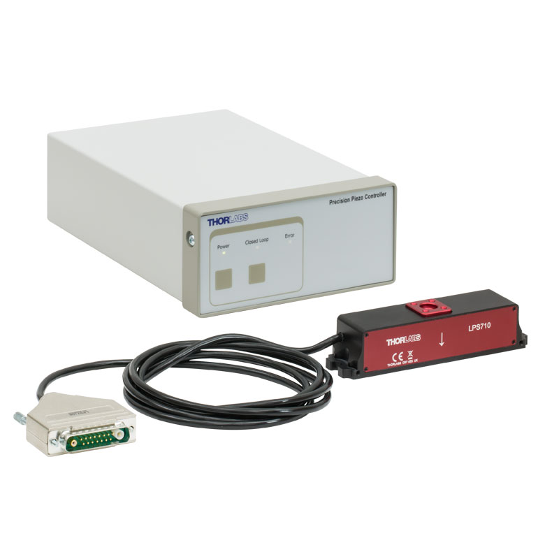
These stages incorporate piezoelectric elements in a variety of drive mechanisms. ORIC® stages incorporate piezo inertia drives that use "stick-slip" friction properties to obtain extended travel ranges. Our Nanoflex™ translation stages use standard piezo chips along with manual actuators. Elliptec® stages use resonant piezo motors to push and pull the moving platform through resonant elliptical motion. Our LPS710E z-axis stage features a mechanically amplified piezo design and includes a matched controller.
| Piezoelectric Stages | ||||||
|---|---|---|---|---|---|---|
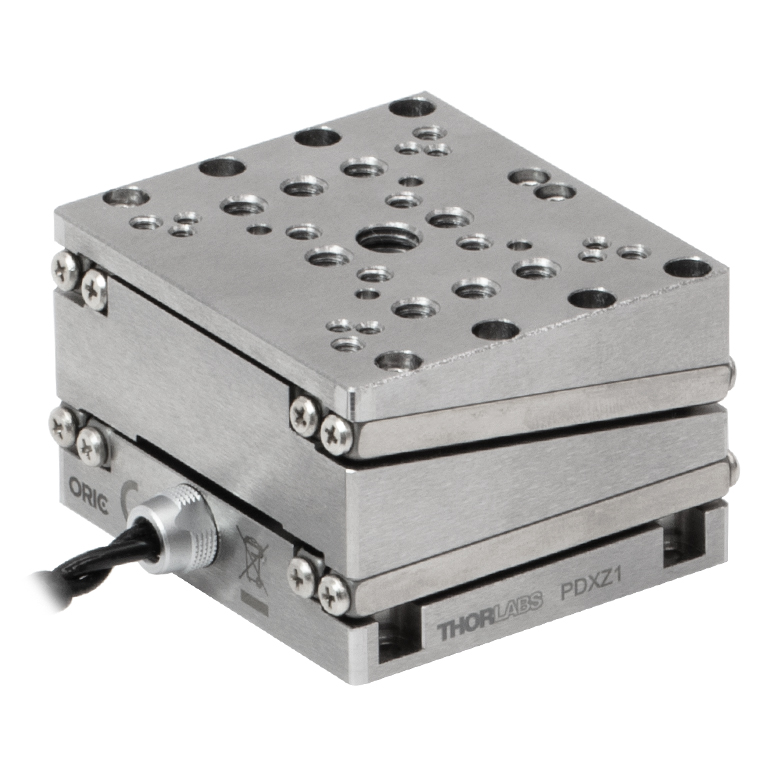
| Product Family | ORIC® PDXZ1 Closed-Loop 4.5 mm Vertical Stage |
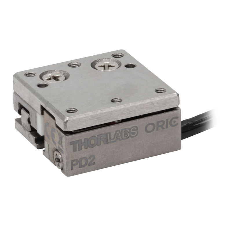
ORIC® PD2 Open-Loop 5 mm Stage |
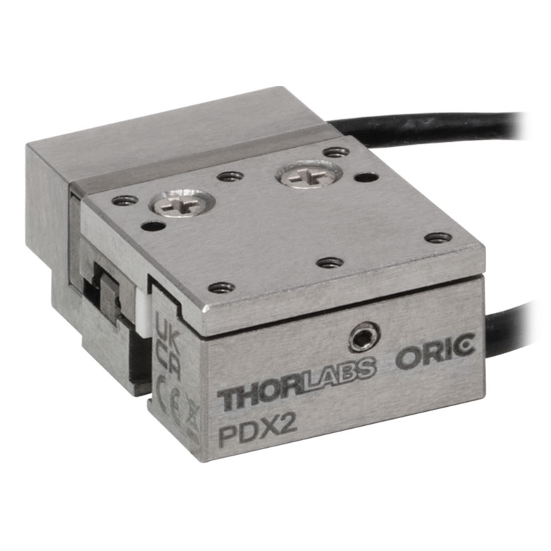
ORIC® PDX2 Closed-Loop 5 mm Stage |
ORIC® PDX4 Closed-Loop 12 mm Stage |
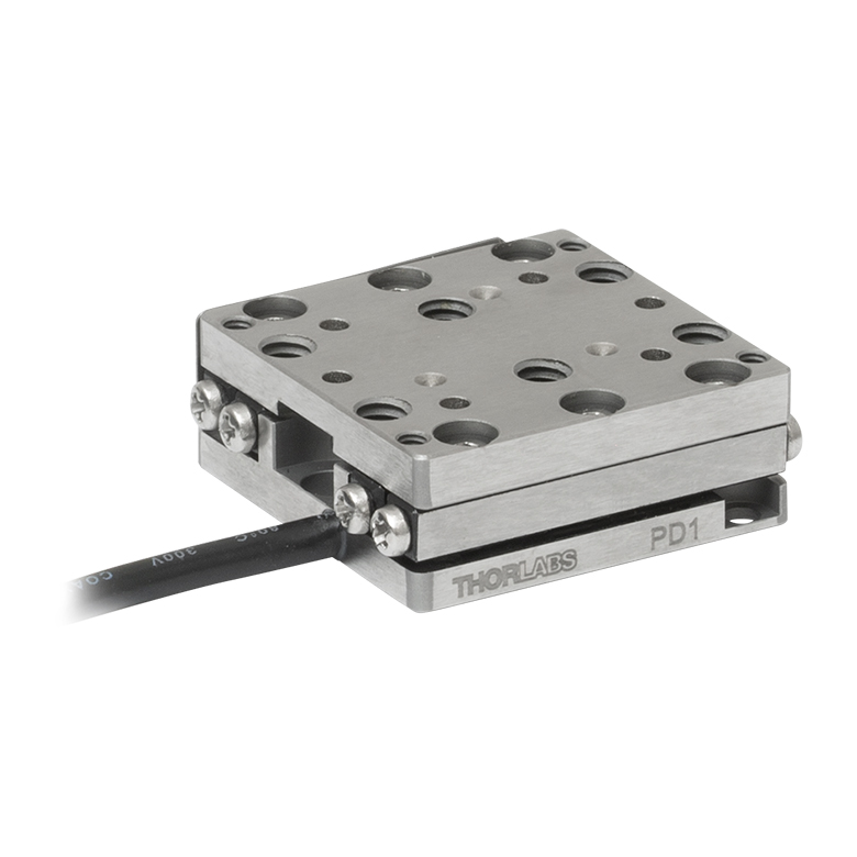
ORIC® PD1 Open-Loop 20 mm Stage |
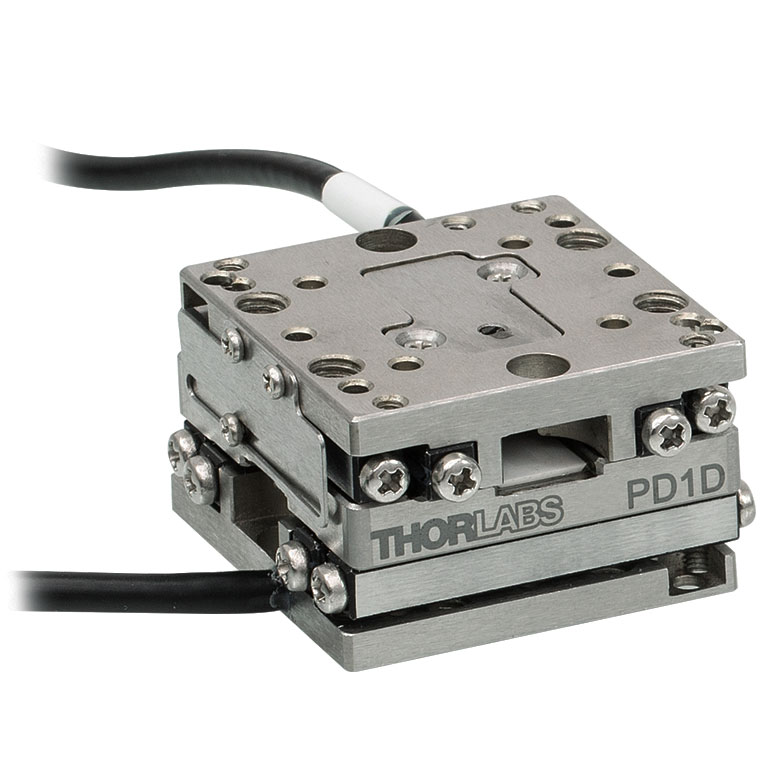
ORIC® PD1D Open-Loop 20 mm Monolithic XY Stage |
| Click Photo to Enlarge |
 |
 |
 |
 |
 |
 |
| Travel | 4.5 mm | 5 mm | 12 mm | 20 mm | ||
| Speed | 1 mm/s (Typ.)a | 10 mm/s (Typ. Max)b | 8 mm/s (Typ.)c | 15 mm/s (Typ.)a,c | 3 mm/s (Typ. Max)d | |
| Drive Type | Piezoelectric Inertia Drive | |||||
| Possible Axis Configurations | Z | X, XY, XYZ | XY, XYZ | |||
| Mounting Surface Size |
45.0 mm x 42.0 mm | 13.0 mm x 13.0 mm | 13.0 mm x 23.0 mm | 30.0 mm x 30.0 mm | ||
| Additional Details | ||||||
| Piezoelectric Stages | ||||||
|---|---|---|---|---|---|---|
| Product Family | ORIC® PDX1 Closed-Loop 20 mm Stage |
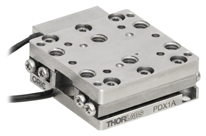
ORIC® PDX1A Closed-Loop 20 mm Stage Low-Profile |
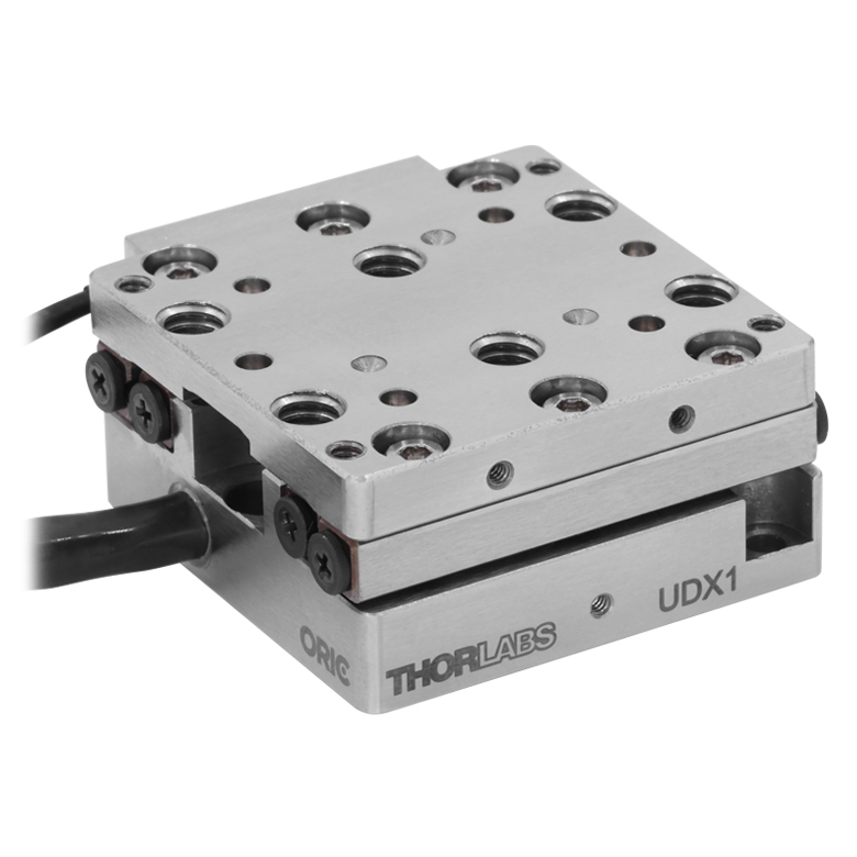
ORIC® UDX1 Ultrasonic Closed-Loop 20 mm Stage |
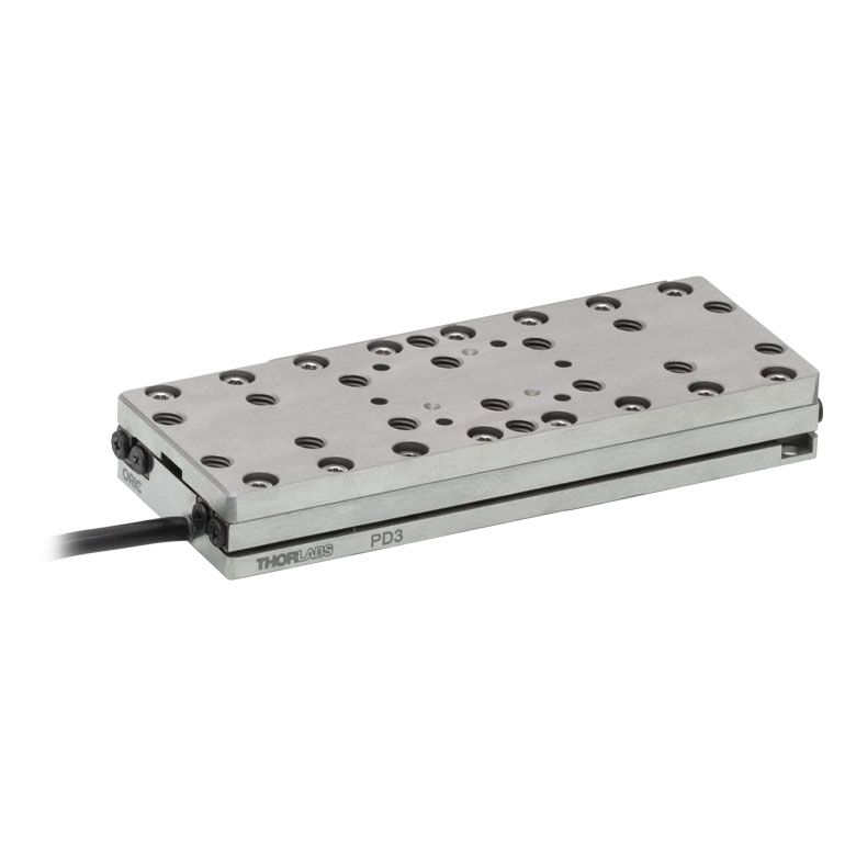
ORIC® PD3 Open-Loop 50 mm Stage |
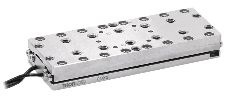
ORIC® PDX3 Closed-Loop 50 mm Stage |
|
| Click Photo to Enlarge |
 |
 |
 |
 |
 |
|
| Travel | 20 mm | 50 mm | ||||
| Speed | 20 mm/s (Typ. Max)a | 10 mm/s (Typ.)b | 100 mm/s (Typ. Max)c | 10 mm/sd | 10 mm/s (Typ. Max)b | |
| Drive Type | Piezoelectric Inertia Drive | Ultrasonic Piezoelectric Drive | Piezoelectric Inertia Drive | |||
| Possible Axis Configurations | X, XY, XYZ | |||||
| Mounting Surface Size |
30.0 mm x 30.0 mm | 80.0 mm x 30.0 mm | ||||
| Additional Details | ||||||
| Piezoelectric Stages | |||||||
|---|---|---|---|---|---|---|---|
| Product Family | Nanoflex™ 20 µm Stage with 5 mm Actuator |
Nanoflex™ 25 µm Stage with 1.5 mm Actuator |
Compact Modular XRN25X 25 mm Stage |
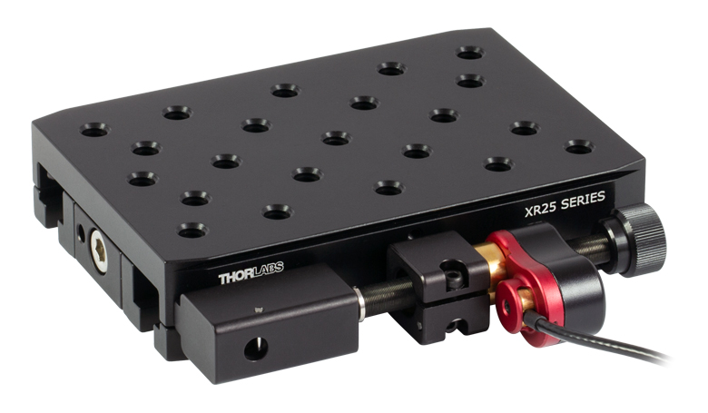
Modular XR25X 25 mm Stage |
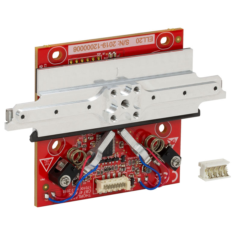
Elliptec® 28 mm Stage | Elliptec® 60 mm Stage | LPS710E 1.1 mm Vertical Stage |
| Click Photo to Enlarge |
 |
 |
 |
 |
 |
 |
 |
| Travel | 20 µm + 5 mm Manual | 25 µm + 1.5 mm Manual | 25 mm | 28 mm | 60.0 mm | 1.1 mm | |
| Maximum Velocity | - | ≤3.6 mm/mina | 180 mm/s | 90 mm/s | - | ||
| Drive Type | Piezo with Manual Actuator | Piezoelectric Inertia Drive | Resonant Piezoelectric Motor | Amplified Piezo | |||
| Possible Axis Configurations | X, XY, XYZ | X, XY, YZ, XZ, XYZ | X | Z | |||
| Mounting Surface Size | 75 mm x 75 mm | 30 mm x 30 mm | 85.0 mm x 50.7 mm | 110.0 mm x 75.7 mm | 15 mm x 15 mm | 21 mm x 21 mm | |
| Additional Details | |||||||
Stepper Motor Stages
These translation stages feature removable or integrated stepper motors and long travel ranges up to 300 mm. Many of these stages either have integrated multi-axis capability (PLSXY) or can be assembled into multi-axis configurations (PLSX, LNR Series, NRT Series, and LTS Series stages). The MLJ150 stage also offers high load capacity vertical translation.
| Stepper Motor Stages | |||||
|---|---|---|---|---|---|
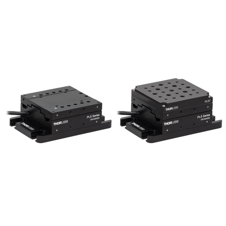
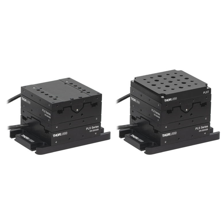
| Product Family | PLSX with and without PLST(/M) Top Plate 1" Stage |
PLSXY with and without PLST(/M) Top Plate 1" Stage |
LNR Series 25 mm Stage |
LNR Series 50 mm Stage |
|
| Click Photo to Enlarge |
 |
 |
 |
 |
|
| Travel | 1" | 25 mm | 50 mm | ||
| Maximum Velocity | 7.0 mm/s | 2.0 mm/s | 50 mm/s | ||
| Possible Axis Configurations |
X, XY | X, XY, XYZ | X, XY, XYZ | ||
| Mounting Surface Size |
3" x 3" | 60 mm x 60 mm | 100 mm x 100 mm | ||
| Additional Details | |||||
| Stepper Motor Stages | |||||||
|---|---|---|---|---|---|---|---|
| Product Family | NRT Series 100 mm Stage |
NRT Series 150 mm Stage |
LTS Series 150 mm Stage |
LTS Series 300 mm Stage |
LTS Series 450 mm Stage |
MLJ250 50 mm Vertical Stage |
|
| Click Photo to Enlarge |
 |
 |
 |
 |
 |
 |
|
| Travel | 100 mm | 150 mm | 150 mm | 300 mm | 400 mm | 50 mm | |
| Maximum Velocity | 30 mm/s | 50 mm/s | 3.0 mm/s | ||||
| Possible Axis Configurations |
X, XY, XYZ | X, XY, XYZ | X, XY | Z | |||
| Mounting Surface Size |
84 mm x 84 mm | 100 mm x 90 mm | 148 mm x 131 mm | ||||
| Additional Details | |||||||
DC Servo Motor Stages
Thorlabs offers linear translation stages with removable or integrated DC servo motors. These stages feature low profiles and many can be assembled in multi-axis configurations.
| DC Servo Motor Stages | ||||
|---|---|---|---|---|
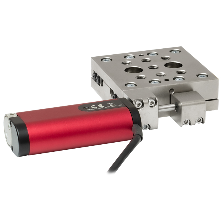
| Product Family | MT Series 12 mm Stages |
PT Series 25 mm Stages |
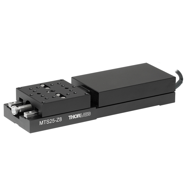
MTS Series 25 mm Stage |
MTS Series 50 mm Stage |
| Click Photo to Enlarge |
 |
 |
 |
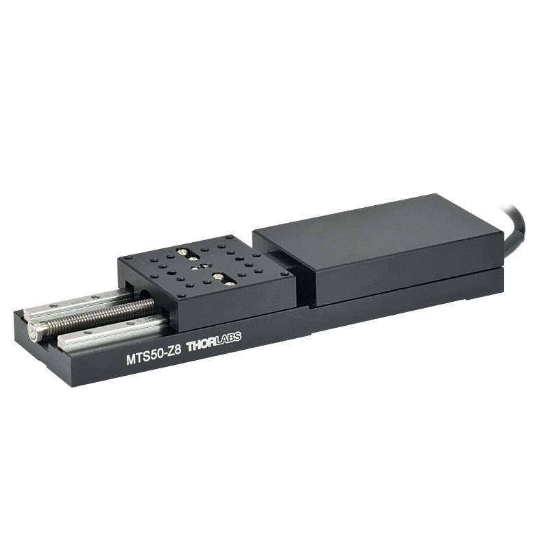 |
| Travel | 12 mm | 25 mm | 25 mm | 50 mm |
| Maximum Velocity | 2.6 mm/s | 2.4 mm/s | ||
| Possible Axis Configurations | X, XY, XYZ | X, XY, XYZ | ||
| Mounting Surface Size |
61 mm x 61 mm | 101.6 mm x 76.2 mm | 43 mm x 43 mm | |
| Additional Details | ||||
| DC Servo Motor Stages | ||||
|---|---|---|---|---|
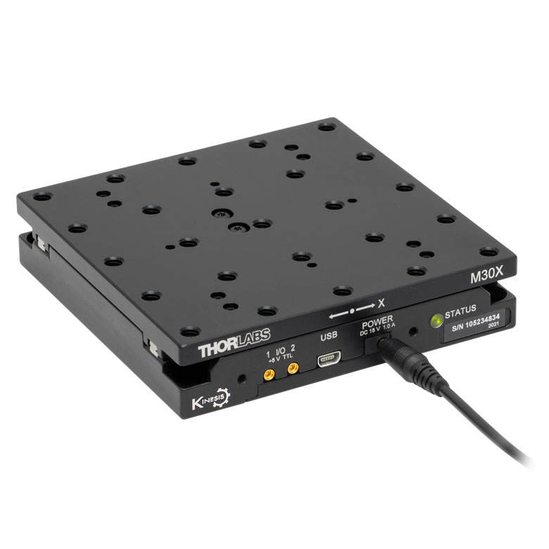
| Product Family | M30 Series 30 mm Stage |
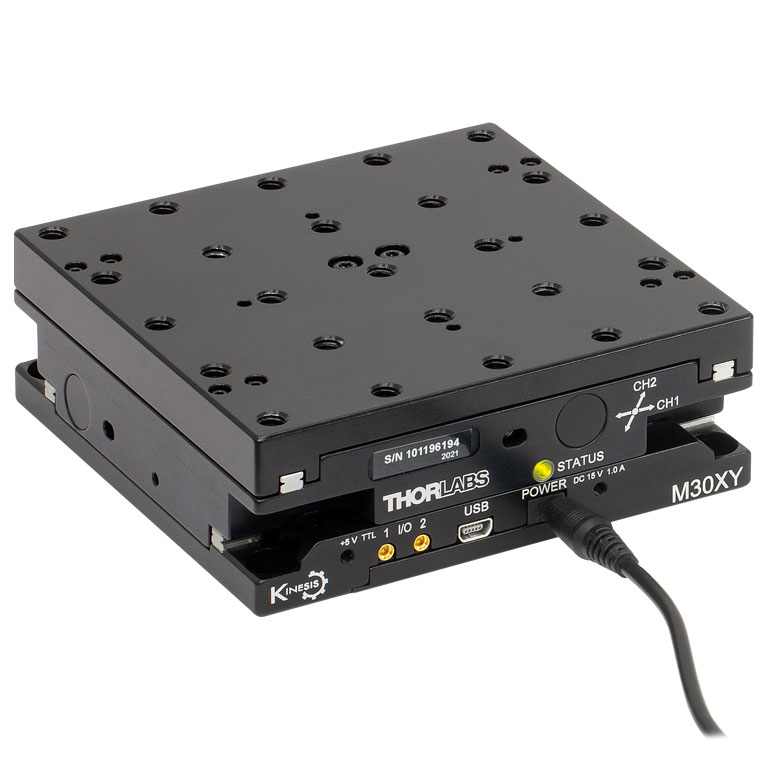
M30 Series 30 mm Monolithic XY Stage |
M150 Series 150 mm XY Stage |
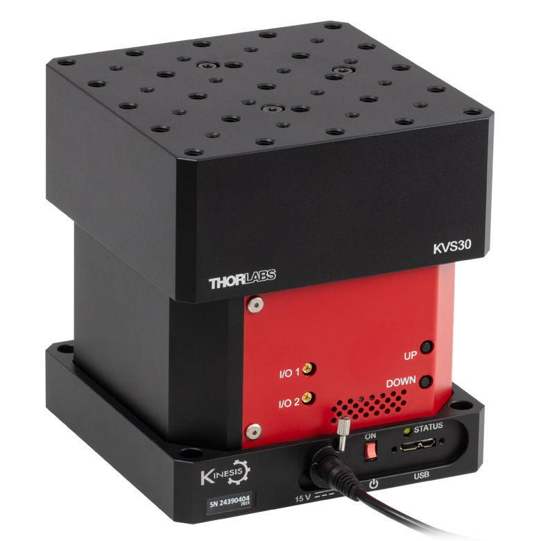
KVS30 30 mm Vertical Stage |
| Click Photo to Enlarge |
 |
 |
 |
 |
| Travel | 30 mm | 150 mm | 30 mm | |
| Maximum Velocity | 2.4 mm/s | X-Axis: 170 mm/s Y-Axis: 230 mm/s |
8.0 mm/s | |
| Possible Axis Configurations | X, Z | XY, XZ | XY | Z |
| Mounting Surface Size |
115 mm x 115 mm | 272.4 mm x 272.4 mm | 116.2 mm x 116.2 mm | |
| Additional Details | ||||
Direct Drive Stages
These low-profile stages feature integrated brushless DC servo motors for high speed translation with zero backlash. When no power is applied, the platforms of these stages have very little inertia and are virtually free running. Hence these stages may not be suitable for applications where the stage's platform needs to remain in a set position when the power is off. We do not recommend mounting these stages vertically.
| Direct Drive Stages | |||||
|---|---|---|---|---|---|
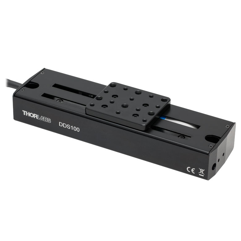
| Product Family | DDS Series 50 mm Stage |
DDS Series 100 mm Stage |
DDS Series 220 mm Stage |
DDS Series 300 mm Stage |
DDS Series 600 mm Stage |
| Click Photo to Enlarge |
 |
 |
 |
 |
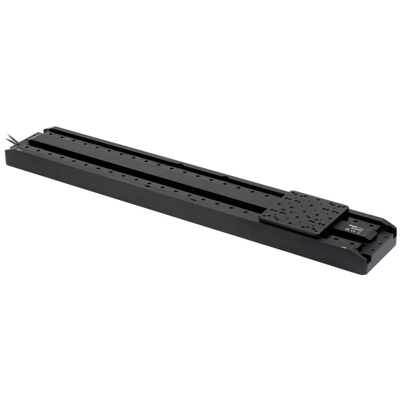 |
| Travel | 50 mm | 100 mm | 220 mm | 300 mm | 600 mm |
| Maximum Velocity | 500 mm/s | 300 mm/s | 400 mm/s | 400 mm/s | |
| Possible Axis Configurations | X, XY | X, XY | X | X | |
| Mounting Surface Size | 60 mm x 52 mm | 88 mm x 88 mm | 120 mm x 120 mm | ||
| Additional Details | |||||

 Zoom
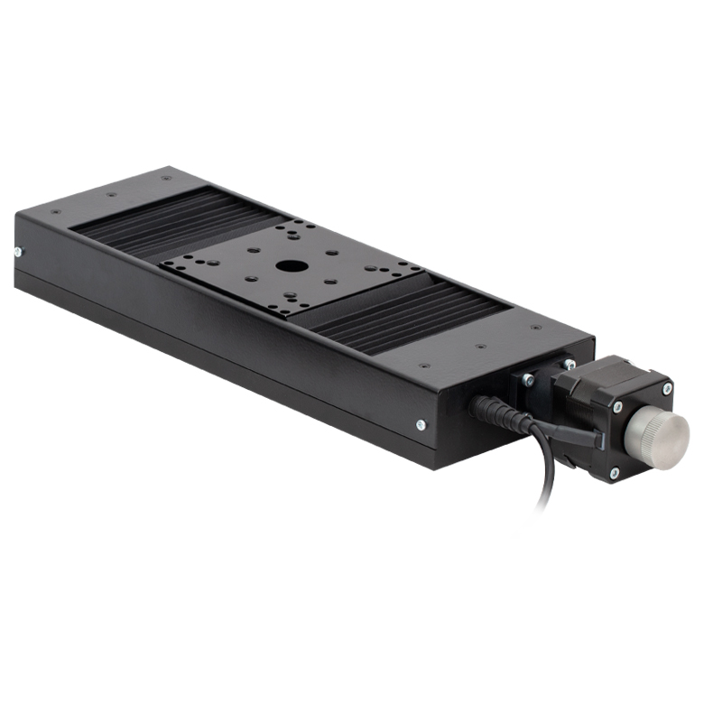
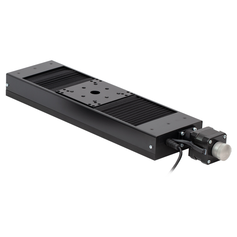
ZoomThorlabs' LTS300C(/M) stage provides 300 mm (11.8") of travel with an integrated stepper motor and controller. The controller features manual keypad and remote computer control. Optomechanics can be directly mounted to the moving platform using sixteen 1/4"-20 (M6) tapped holes, which are spaced 1.0" (25.0 mm) apart.

 Zoom
Zoom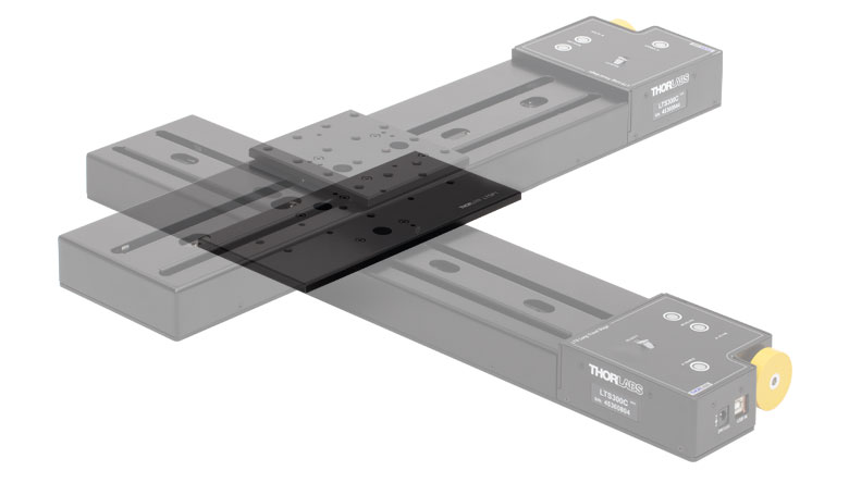
Click to Enlarge
Figure G2.1 LTS300C Stages Mounted in XY Configuration Using an LTSP1 Adapter Plate
- Mount LTS300C(/M) and LTS150C(/M) Stages in XY Configurations
- Stages can be Mounted in Left- or Right-Handed Setups
- Dowels Included to Ensure Orthogonality
The LTSP1(/M) is a spacer plate, allowing any two LTS translation stages to be mounted in an XY configuration. When assembled as shown in Figure G2.1, the working height of the upper stage is 3.15" (80 mm). The spatial dimensions of the stage configuration will depend on the orientation (left-handed or right-handed) of the X and Y stages. Please contact Tech Support for the exact dimensions of a particular setup.

 Zoom
Zoom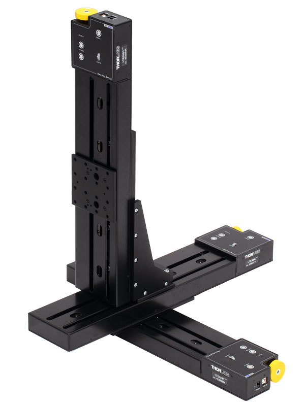
Click to Enlarge
Figure G3.2 Three LTS300C Stages Mounted in XYZ Configuration Using an LTSP3 Bracket and LTSP1 Plate

Click to Enlarge
Figure G3.1 Two LTS300C Stages Mounted in XZ Configuration Using an LTSP3 Bracket
- Mount an LTS300C(/M) Stage in XZ and XYZ Configurations
- Stage can be Mounted in Left- or Right-Handed Setups
- Not Designed for Direct Breadboard Mounting (See Below)
The LTSP3(/M) right-angle bracket allows an LTS300C(/M) stage to be mounted in a vertical (Z-axis) orientation as shown in Figure G3.1. XYZ configurations can be made using an LTSP1(/M) adapter plate (sold above) and LTSP3(/M) angle bracket.
Please note that these adapters are not designed for mounting directly to a breadboard. The bottom of the vertical stage extends past the base of the adapter, and thus, the adapter must be elevated above the table to provide adequate clearance for the stage.