 Products Home
UV Fused Silica Engineered Diffusers®
- Circular Scatter Shape
- Design Wavelength: 400 nm - 700 nm
- Transmission: 90%
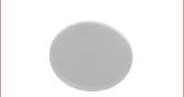
- Unmounted and Mounted Ø1/2" Diffusers Available
EDG5CD5
0.5° Circle Pattern,
Unmounted
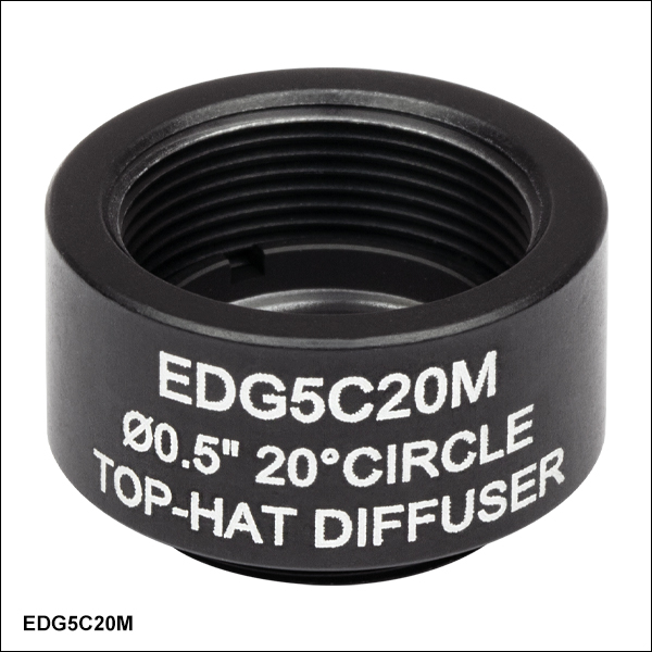
EDG5C20M
20° Circle Pattern,
Mounted
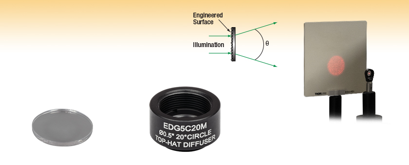
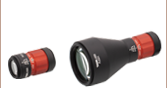
Application Idea
An EDG5C20 Engineered Diffuser, mounted with an LMR05 Lens Mount, in the light path of a S1FC635 Laser. The circular scatter pattern is visible on a post-mounted EDU-VS1 Viewing Screen.


Please Wait
| Diffuser Selection Guide | |||
|---|---|---|---|
| Ground Glass Diffusers | |||
| Type | Material | Mounting, Coating | Operating Wavelength |
| Standard Diffusers | N-BK7 Substrate | Unmounted, Uncoated | 350 nm - 2.0 μm |
| Unmounted, AR Coated | 350 nm - 700 nm 650 nm - 1050 nm |
||
| Mounted, Uncoated | 350 nm - 2.0 µm | ||
| UVFS Substrate | Unmounted, Uncoated | 185 nm - 2.0 µm | |
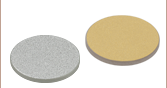
| Diffuse Reflectors | N-BK7 Substrate | Unmounted, UV-Enhanced Aluminum Coated |
250 nm - 450 nm |
| Unmounted, Protected Silver Coated | 450 nm - 20 µm | ||
| Unmounted, Protected Gold Coated | 800 nm - 20 µm | ||
| Alignment Disks | |||
| Engineered Diffusers | |||
| Type | Material | Mounting, Coating | Operating Wavelength |
| Glass Diffusers | UVFS Substrate | Unmounted and Mounted, Uncoated | 400 nm - 700 nm |
| Polymer Diffusers | ZEONOR Substrate | Unmounted and Mounted, Uncoated | 400 nm - 700 nm |
| Diffuser Kits | |||
Features
- Ø1/2" Diffusers with Circle Scatter Pattern
- Divergence Angles Available from 0.5° to 20°
- Input Illumination Homogenized to a Top-Hat Intensity Profile
- UV Fused Silica Substrate
- Design Wavelength Range from 400 nm - 700 nm
- 90% Transmission Efficiency from 193 nm - 2.0 µm
- Available Unmounted or Mounted
- Ideal for High-Power Applications
Applications
- Hot Spot and Modal Anomaly Removal in Solid State Lasers
- Asymmetric Divergence Removal in Semiconductor Lasers
- Flat Field Generation for Dermatological and Aesthetic Lasers
Thorlabs offers UV Fused Silica Engineered Diffusers®*, which homogenize input beams and provide non-Gaussian intensity distributions with a top-hat profile (see the Graphs tab). These diffusers have a circular distribution pattern with a 0.5°, 1°, 5°, 10°, or 20° divergence angle over their design wavelength range; typical diffusers do not offer this advanced level of control over the divergence angle, spatial distribution of the illumination, and intensity profile.
These diffusers are made from UV fused silica and have 90% transmission efficiency from 193 nm to 2.0 μm. UV fused silica has a high damage threshold, making these diffusers ideal for high-power applications and laser sources including pulsed, fiber, solid state, and semiconductor lasers. These diffusers are designed for use with beam diameters larger than Ø0.5 mm; smaller beams should be expanded prior to the diffuser. For low-power applications, Thorlabs offers cost-effective Polymer Engineered Diffusers.
These UV Fused Silica Engineered Diffusers are available unmounted or mounted. The mounted Ø1/2" diffusers come in engraved SM05-threaded (0.535"-40) mounts, as shown at the top of the webpage. Each mount is engraved with the Item #, optic size, divergence, and diffuser type for easy identification and helps protect the diffuser from fingerprints and other contamination. SM05 threading is particularly useful when building
Please see the Technology tab for more information on the technology and fabrication of these Engineered Diffusers.
*Engineered Diffusers® is a registered trademark of VIAVI Solutions, Inc.
| General Specifications | ||
|---|---|---|
| Material | UV Fused Silicaa | |
| Design Wavelengthb | 400 - 700 nm (Achromatic) | |
| Transmission Spectrumb | 193 - 2000 nm | |
| Transmission Efficiency | 90% | |
| Diffuser Diameter | Ø12.7 mm (Ø1/2") | |
| Diffuser Thickness | 1.0 mm (0.04") | |
| Clear Aperture | Unmounted | Ø11.43 mm |
| Mounted | Ø10.9 mm | |
| Surface Quality | 80-50 Scratch-Dig | |
| Incident Beam Size | >0.5 mm | |
| Index of Refraction | 1.457 @ 633 nm | |
| Item # | Divergencea | Pattern |
|---|---|---|
| EDG5CD5(/M) | 0.5° ± 10% FWHM | Circle |
| EDG5C1(/M) | 1° ± 10% FWHM | |
| EDG5C5(/M) | 5° ± 10% FWHM | |
| EDG5C10(/M) | 10° ± 10% FWHM | |
| EDG5C20(/M) | 20° ± 10% FWHM |
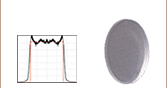
The graphs below show the theoretical and experimental beam profile for each UV Fused Silica Engineered Diffuser®. The theoretical data is an approximation of the intensity through the center of the diverging beam profile when illuminating the diffuser with a 633 nm collimated beam, and is normalized to the relative intensity at 0°. The experimental intensity data was collected using the scatterometer set-up described below with a Ø1.0 mm, 635 nm collimated beam and is an average over measurements on 20 independent diffusers with each individual measurement normalized to its 0° value. The highlighted region denotes the specified divergence angle of the diffuser, which is defined by the FWHM of the relative intensity at 0°.
Click to Enlarge
Click Here for Raw Data
The theoretical and experimental beam profile for the EDG5CD5 UV Fused Silica
Engineered Diffuser. The highlighted region denotes the specified divergence angle.
Click to Enlarge
Click Here for Raw Data
The theoretical and experimental beam profile for the EDG5C1 UV Fused Silica
Engineered Diffuser. The highlighted region denotes the specified divergence angle.
Click to Enlarge
Click Here for Raw Data
The theoretical and experimental beam profile for the EDG5C5 UV Fused Silica
Engineered Diffuser. The highlighted region denotes the specified divergence angle.
Click to Enlarge
Click Here for Raw Data
The theoretical and experimental beam profile for the EDG5C10 UV Fused Silica
Engineered Diffuser. The highlighted region denotes the specified divergence angle.
Click to Enlarge
Click Here for Raw Data
The theoretical and experimental beam profile for the EDG5C20 UV Fused Silica Engineered Diffuser. The highlighted region denotes the specified divergence angle.
Click to Enlarge
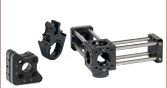
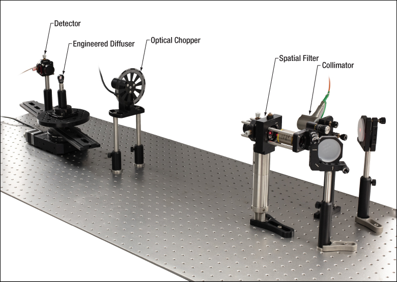
A scatterometer was built to measure the scattered light from a UV Fused Silica Engineered Diffuser to characterize the beam profile.

Click to Enlarge
Illustration of the Detector Path through the Beam Profile
Experimental Procedure
A scatterometer was built to measure the scatter pattern of a Ø1.0 mm, 635 nm laser beam through a UV Fused Silica Engineered Diffuser. The experimental set-up is displayed in the photo to the right, and a list of parts can be found below the photo. Please note that a lock-in amplifier was used in the experimental set-up but is not included in the list. The output of an S1FC635 fiber laser was collimated using an RC12FC-P01 collimator, and then a KT311 spatial filter system was used to produce a clean and spatially uniform Gaussian beam. The collimated beam was modulated using an MC2000B optical chopper synced with a lock-in amplifier and was incident upon the diffuser under test. The diffuser was mounted to a QRP02 rotation platform, which was connected to an MBR6 aluminum breadboard and attached directly to the optical table through the central aperture of an HDR50 rotation mount. An XRN25DR3 rail with an attached SM05PD3A photodiode was connected to the rotation mount, allowing the detector to sweep through the center of the diffuser's exiting divergent beam profile, as depicted in the image to the right. The detector was mounted approximately 13.5 cm from the diffuser, and the output angle was defined with respect to the original optical axis when the diffuser was not within the path. The detector was synced with the lock-in amplifier and signal was collected every 0.1° using a LabVIEW program for instrument control and data acquisition. The normalized intensity was plotted as a function of output angle.
Key to this experiment was the use of a spatial filter and lock-in amplifier synced with an optical chopper and photodiode detector. This configuration enabled the detection of low intensity scatter from the diffuser, providing a precise measurement of the beam profile.
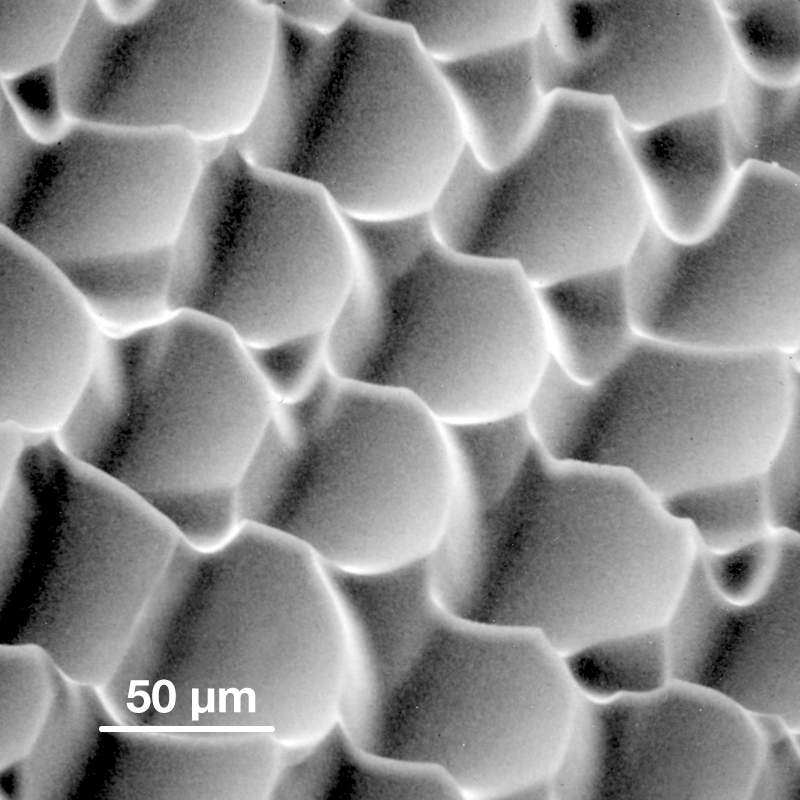
Click to Enlarge
SEM Picture of Engineered Diffuser for Display Brightness Enhancement
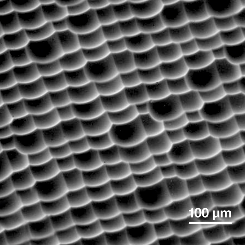
Click to Enlarge
SEM Picture of Engineered Diffuser for Projection Screens
Engineered Diffuser® Technology
Engineered Diffusers provide advanced beam shaping that leads to significant performance enhancements for applications as diverse as lithographic systems, outdoor lighting, displays, backlighting, display brightness enhancement, and projection screens.
Homogeneous diffusers made of, for example, ground glass, opal glass, or holographic elements, consist of repeating, uniform surface patterns across the entire clear aperture that provide only limited control over the shape and intensity profile of the illuminated area, causing the incident light to be used inefficiently. In addition, holographic diffusers are usually limited to monochromatic applications using coherent light. On the other hand, Engineered Diffusers consist of differing, individually manipulated microlens units that provide broadband compatibility and excellent control over the light distribution and beam profile.
Each microlens unit that forms the diffuser is individually specified with respect to its surface profile and location in the array. At the same time, to ensure that the diffuser is stable against variations in the input beam's intensity profile and usable in the visible and IR, the distribution of microlenses is randomized according to probability distribution functions chosen to implement the desired beam shaping functions. The microlens distribution also removes zero-order bright spots and diffraction artifacts from the output. In this manner, Engineered Diffusers retain the best properties of both random and deterministic diffusers.
Click to Enlarge
Diagram of Mastering Process
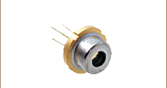
Fabrication
The master microlens array is produced by a laser writing system developed by VIAVI Solutions, Inc. This system exposes a thick layer of photoresist point-by-point in a raster scan mode, as shown to the left. By modulating the intensity of the laser beam as it is scanned, the degree to which the photoresist is exposed can be varied. A deeply textured, engineered surface is the result, as shown above in the two SEM images of the surface topography.
Comparison to Other Diffuser Technologies
Other common diffuser types include prismatic glass integrating bars, ground glass, opal glass, holographic diffusers, and diffractive diffusers. Prismatic glass integrating bars, though sometimes used in high-end systems, are expensive and occupy a great deal of precious space. Ground and opal glass scatter light equally in all directions but with a low degree of control. In addition, efficiency is generally poor with these simple diffusers. Holographic diffusers are an improvement on these technologies and enable limited production of light distribution patterns, but only offer Gaussian-like intensity profiles and circular or elliptical patterns. In terms of general beam shaping capability, diffractive elements can shape an input beam arbitrarily. However, they are confined to narrow diffusion angles, highly sensitive to wavelength, and cannot eliminate zero-order bright spots collinear with the incident beam. In contrast, Engineered Diffusers provide high transmission efficiencies and the ability to control the divergence angle, spatial distribution, and intensity profile of the diffused light.
For more information on Engineered Diffuser technology and performance, please read our Optical Diffusers Catalog Presentation.
| Posted Comments: | |
zhenhua xiao
(posted 2025-02-19 13:14:05.78) what is the damager threshhold for 355nm laser blarowe
(posted 2025-02-27 09:57:26.0) Thank you for contacting Thorlabs. Unfortunately, we don't have an official damage threshold for these diffusers at 355nm, though I have reached out to you directly to discuss your specific laser and application. Gerrit Boschloo
(posted 2024-10-11 12:57:25.39) I was wondering if this diffuser can be used to get a top-hat profile for a ns-pulsed Nd:YAG laser?
The rep. rate is 10 Hz, with about 10 mJ/puls at 532 nm. mgarodia
(posted 2024-10-18 03:21:55.0) Thank you for reaching out to us. Yes, your laser will be suitable with the EDG5C20M and you can get a top-hat profile with it. I have reached out to you with further information. |

 Zoom
Zoom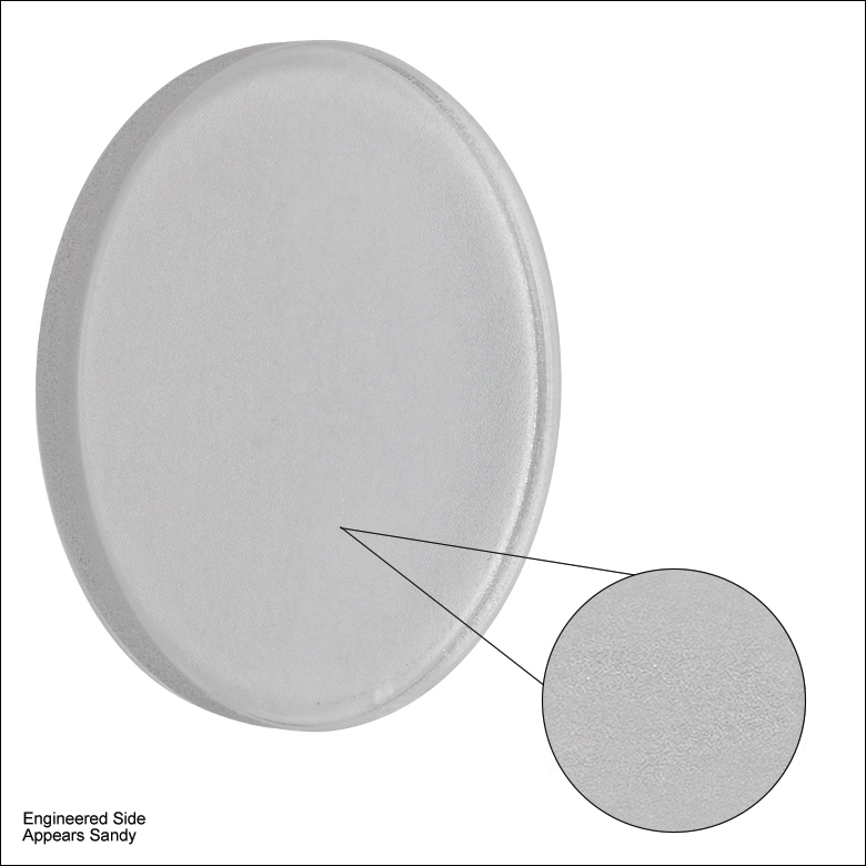
- Ø1/2" Engineered Diffusers®
- Top-Hat Intensity Profile (See Graphs Tab)
- UV Fused Silica Substrate
- Circle Pattern with 0.5°, 1°, 5°, 10°, or 20° Divergence Angle
Unmounted optics are ideal for applications that are tight on space or that need added mounting flexibility. These Ø1/2" Unmounted UV Fused Silica Engineered Diffusers can be used in SM05-threaded (0.535"-40) lens tubes and SM05-compatible mounts. The optics should be oriented so that incident light hits the engineered surface first.

 Zoom
Zoom
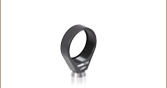
- Ø1/2" Engineered Diffusers® in SM05-Threaded Mounts
- Top-Hat Intensity Profile (See Graphs Tab)
- UV Fused Silica Substrate
- Circle Pattern with 0.5°, 1°, 5°, 10°, or 20° Divergence Angle
These Mounted UV Fused Silica Engineered Diffusers are the same as their unmounted counterparts, but are set in an engraved mount with internal and external SM05-threading (0.535"-40). Mounted optics have the advantage that they are easy to identify and the optics are recessed in the mount so that they are better protected from contamination than unmounted optics. The optics should be oriented so that incident light hits the engineered surface first; when the optics are placed in their mount, this surface will face the retaining ring.